Hello friends, I hope you all are doing great. Today, I am going to share the new Electric Bell Library for Proteus V1.0. The electric bell is the sound of school corridors, factory shift changes, fire alarms and old doorbells: a red gong, a small hammer and a loud, rattling ring. Inside, it is one of the oldest tricks in electromechanics - the trembler bell, a coil that switches itself off as soon as it pulls, so a steady DC voltage on two terminals turns into twenty-odd strikes a second.
Electric Bell Library for Proteus
Latest version: V1.0 (November 2026, this tutorial)
Other motors: SG90 Servo · TT Gear Motor · 28BYJ-48 Stepper · NEMA 17 Stepper · MG996R Servo · N20 Encoder Motor · JGA25-370 Encoder Motor · FS90R 360 Servo · 130 DC Motor · A2212 Brushless · X27.168 Gauge · Analog Panel Meter · DC Tachogenerator · LM393 Speed Sensor · MG90S Servo · DS3218 Servo · L12 Linear Servo · JGB37-520 Motor · RS-775 Motor · JGY-370 Worm Motor · 12V Linear Actuator · Coin Vibration Motor · Mini Submersible Water Pump · 12V Peristaltic Pump · 4-Pin PC Fan · 12V Push-Pull Solenoid · NEMA 23 Stepper Motor · Micro Linear Stepper · TYJ50 Synchronous Motor · Quartz Clock Movement · Air-Core Gauge · Electromechanical Counter · Split-Flap Display · Wind Turbine · 8520 Coreless Motor · Car Wiper Motor · Car Door Lock Actuator · 12V Solenoid Water Valve · 12V Holding Electromagnet
Motor drivers: L298 · L9110S · TB6612FNG · BTS7960 · A4988 / DRV8825 · 28BYJ-48 + ULN2003 · PCA9685 Servo · Relay Module · 30A Brushless ESC · TB6600 Stepper Driver
Helping Tools
- Serial Monitor Advance: a serial terminal window for the UART of your board
- Serial Monitor Expert: the serial monitor with extra debugging tools
- LCD Library for Proteus V3.0: 16x2, 20x4 and I2C LCDs to show your readings
This library gives that bell a part of its own in Proteus. Its coils are in the circuit with their resistance and an inductance that changes as the armature moves, its interrupter contact really opens and closes the circuit, and its hammer really strikes the gong - or fails to, when the supply is too low or the sketch tries to drive it with a PWM. A pop-up window shows the gong, the hammer, the chopped current and the reason for every silent ring. The demo rings it from an Arduino UNO V4.0 through our L9110S motor driver.
NOTICE: an electric bell looks like the simplest part on any sheet - two wires and a gong - but its ring comes from a coil, a spring and a contact working against each other twenty-five times a second. Our team put a lot of effort into building a bell that rings for the right reasons, stays silent for the right reasons, and tells you which. Your feedback is the fuel that keeps us going, so please tell us what you think in the comments below or in the Motor Driver board of our forum. And if our free libraries help you, you can buy us a coffee. So, let's get started with the Electric Bell Library for Proteus V1.0:
What is an Electric Bell?
An electric bell turns a steady current into a fast series of strikes. The common kind is the trembler bell, also called a vibrating or interrupter bell. Two coils on a U-shaped steel yoke form an electromagnet. In front of its poles hangs an iron armature on a flat spring, and the armature carries a rod with the hammer at its end. A contact screw touches a spring on the armature, and that contact is wired in series with the coils. That is the whole trick: the bell switches its own coils.
| Electric bell (the model) | |
|---|---|
| Type | a 12 V DC trembler bell: two coils, an armature on a spring, an interrupter contact, a hammer and a gong |
| Coils | 24 ohm at 25 C; 36 mH with the armature open, 103 mH with it at the pole |
| Current | rated 0.5 A; 0.47 A peaks at 12 V; the armature pulls in from 316 mA (7.6 V) |
| Ring | about 26 strikes a second at 12 V; it still rings at 8.5 V |
| Contact | opens below a 0.9 mm gap at the pole, closes again above 1.5 mm |
| Ratings | VOLTAGE 6 (6 ohm, 1 A), 12 (24 ohm, 0.5 A) or 24 (96 ohm, 0.25 A) |
How the Trembler Works
Put 12 V on the terminals. Current flows through the closed contact and the coils, the magnet pulls the armature in, and the hammer swings towards the gong. Part of the way in, the armature's spring leaves the contact screw: the circuit is open, the coils let go, and the hammer flies on and strikes the gong. The spring throws the armature back, the contact closes again, the current builds up again, and the whole cycle repeats. In the model, the contact opens when the gap at the pole falls below 0.9 mm and closes again above 1.5 mm, and the hammer meets the gong at 0.4 mm. One cycle takes under 40 ms - about 26 strikes a second.
Why Steady DC?
Because the bell does its own switching, the right drive is plain DC for as long as you want it to ring: on for the ring, off for silence. A PWM works against it. The coils are an inductor that averages fast pulses, so a 50 % PWM looks like about 6 V to them - not enough current to pull the armature at all, and the hammer never moves. Too little voltage does the same thing. Too much voltage rings it harder and faster, but pushes more current through coils that are only made for short rings.
Why Does a Bell Need a Driver?
A 12 V bell takes up to half an amp - more than twenty times what an Arduino pin should ever give, at a voltage the pin cannot give at all. Its coils also kick back every time the contact opens. So a bell is always switched through something: a transistor or a logic MOSFET with a diode across the bell, a relay, or an H-bridge such as the L9110S in our demo.
What's New in Electric Bell Library for Proteus V1.0
- A part of its own: a 12 V DC trembler bell drawn with its lid off: the red gong, the hammer, the two copper coils, the armature and the brass terminals.
- The real coils: a resistance that grows as they warm and an inductance that grows as the armature closes, in the circuit while the contact is closed.
- The real trembler: the contact opens and closes the circuit with the armature, so steady DC becomes about 26 strikes a second by itself.
- The real failures: too low a voltage, a PWM drive or the wrong rating - the hammer stops short or never moves, and the model says why.
- A pop-up window with four pages - Bell, Graphs, Event log and Check - with the gong, the hammer and the chopped current drawn live.
- An A3 demo on our Arduino UNO V4.0 with our L9110S driver: a ring, a doorbell, a school bell, an alarm and a PWM test.
The Electric Bell in Proteus
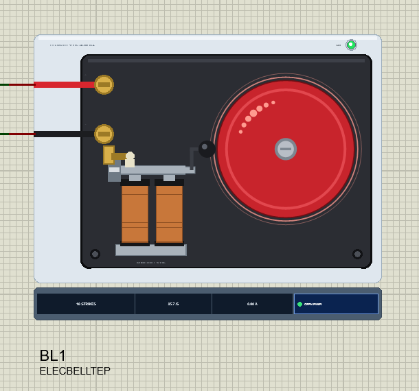
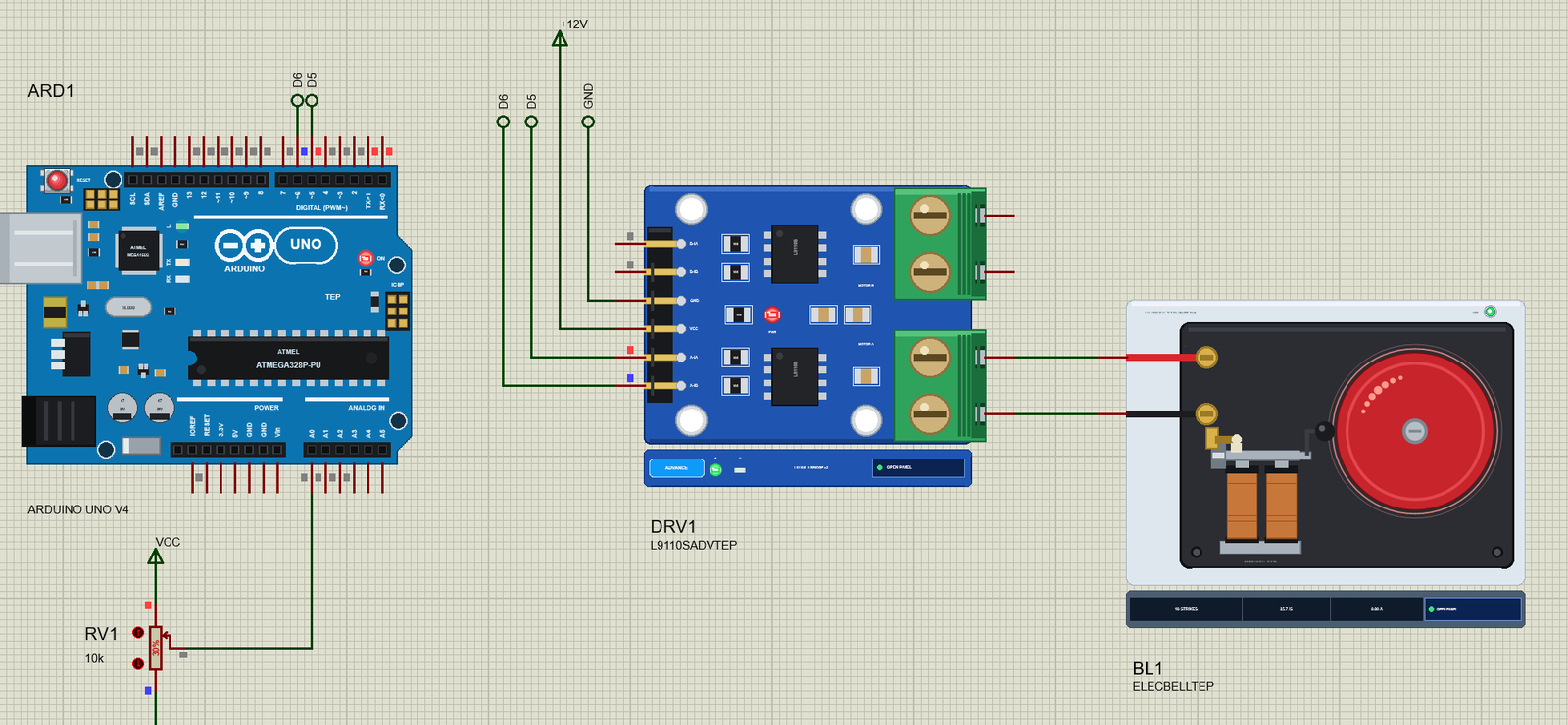
Search bell in Pick Devices; the device ELECBELLTEP is in TEPBELL.LIB (category Electromechanical, Motors) and its model is TEPBELL.DLL. It is drawn with the lid off, the way a bell looks on the workbench: the dark base with its mounting screws, the big red gong with its centre screw, the two copper coil bobbins on their steel yoke, the armature on its hinge spring with the contact screw in its brass post, the rod with the black hammer beside the gong's rim, and the two brass screw terminals with the red + and black - wires.
At Run, the hammer swings between its rest position and the gong, and faint rings spread around the gong's rim while it rings. The COIL LED in the corner lights green while current flows; it is held for 0.15 s, so the trembler's fast pulses show as a steady light rather than a flicker. The strip under the plate shows the strikes so far, the strike rate, the current and the OPEN PANEL button. The plate, the LED, the rating line and the strip are TEP additions; the real bell has none of them.
The Pins and the Property
| Pin | What the model does with it |
|---|---|
| + | one end of the coils, through the interrupter contact: the positive side of the supply |
| - | the other end of the coils: the negative side of the supply |
| Property | Default | What it does |
|---|---|---|
| VOLTAGE | 12 | the bell's rating: 6 (6 ohm, 1 A), 12 (24 ohm, 0.5 A) or 24 (96 ohm, 0.25 A) |
The three ratings are the same bell wound for a different supply: a 6 V bell has a quarter of the 12 V bell's resistance, a 24 V bell four times as much, so each one rings the same way on its own voltage. Put a 12 V bell on 24 V and it rings faster and draws far more current than its coils are made for; put a 24 V bell on 12 V and it never pulls in.
Download Electric Bell Library for Proteus
Click the button below to download Electric-Bell-Library-for-Proteus-v1.0.zip (about 1.2 MB, without the source code of the models):
Electric Bell Library for Proteus V1.0- README.txt: installation, the demo, the wiring, the property, real hardware, troubleshooting and the limits.
- Proteus Library Files:
TEPBELL.LIBandArduinoV4TEP.LIBfrom our Arduino Library for Proteus V4.0. - Proteus Model Files:
TEPBELL.DLLandTEPARDUINO.DLL. - Proteus Simulation:
Electric-Bell-L9110S-ArduinoUnoV4.pdsprj,Bell_Demo.hexand copies of the two DLLs. - Arduino Code:
Bell_Demo.ino(no library needed).
Good to know: the demo's driver is our L9110S Motor Driver, a separate library that is not in this zip. Download it from its own article, the L9110S Motor Driver Library for Proteus, and install TEPL9110S.LIB and TEPL9110S.DLL the same way.
No Proteus yet? Read How to Download and Install Proteus 7 and 8. New to libraries? Follow How to Install a New Library in Proteus.
How to Install Electric Bell Library for Proteus
- Close Proteus and extract the whole zip file, for example to your Desktop.
- Copy
TEPBELL.LIBandArduinoV4TEP.LIBfrom Proteus Library Files into the LIBRARY folder of Proteus (usuallyC:\Program Files (x86)\Labcenter Electronics\Proteus 8 Professional\LIBRARY). - Copy
TEPBELL.DLLandTEPARDUINO.DLLfrom Proteus Model Files into the MODELS folder. The two Arduino files are the ones of our Arduino Library V4.0; if you have it, they are the same. - Install the L9110S library the same way if you do not have it yet.
- Delete
TEPBELL.IDXfrom the LIBRARY folder if it is there. - Start Proteus, press P and search for bell.
Tip: keep the Proteus Simulation folder together, because the project needs its .hex file and the DLLs beside it. The library is tested in Proteus 8.5; Proteus 7 is not supported.
The Demo Circuit
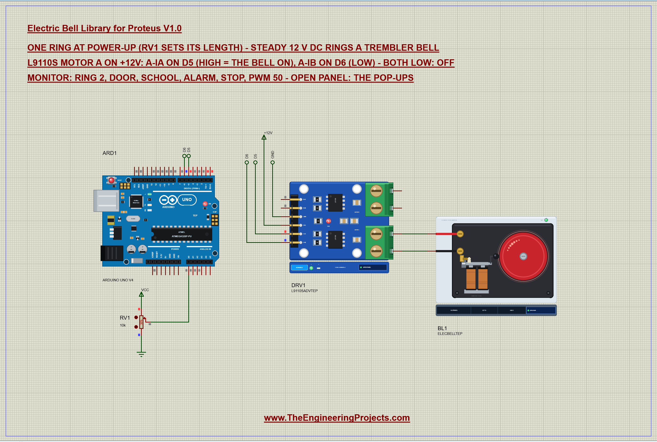
Open Electric-Bell-L9110S-ArduinoUnoV4.pdsprj. ARD1 is an Arduino UNO V4.0 from our Arduino UNO Library for Proteus V4.0, running Bell_Demo.hex with its serial monitor built in. DRV1 is our L9110S driver in its pop-up version, on +12V. BL1 is the bell on the L9110S's motor A outputs, and RV1 is a 10k pot on A0 that sets how long a plain ring lasts, from 0.1 to 3 s.
| Part | Pin | Goes to |
|---|---|---|
| L9110S | A-IA, A-IB | D5, D6 (by net labels) |
| L9110S | VCC, GND | +12V, ground |
| L9110S | A-OA, A-OB | the bell's + and - (straight wires) |
| RV1 | wiper | A0 |
Why an L9110S?
The L9110S is a small dual H-bridge for 2.5 - 12 V. On 12 V, its motor A output puts the whole supply across the bell when A-IA is HIGH and A-IB is LOW; both LOW is the brake - both outputs to ground and the bell silent. Its inputs stay 5 V logic, so the UNO drives them directly. A bell only ever needs one direction, so a single transistor would do as well; the demo uses the L9110S because it is a ready board with a pop-up of its own, so you can watch the switch and the bell side by side.
The Arduino Code
The sketch needs no library: switching a bell is two digitalWrite() calls. New to Arduino? Start with Arduino Tutorial for Beginners and Introduction to Arduino UNO. The pins come first:
const byte BELL_A = 5, BELL_B = 6;            // L9110S A-IA / A-IB (A-OA to +, A-OB to -)
const byte KNOB = A0;
The function that does the switching is short. D6 always stays LOW; D5 HIGH puts 12 V on the bell, and D5 LOW brakes it. The PWM branch is there only for the pwm test - a real bell sketch never needs it:
void bell(bool on) {
  digitalWrite(BELL_B, LOW);
  if (on && duty < 100) analogWrite(BELL_A, (int)duty * 255 / 100);
  else digitalWrite(BELL_A, on ? HIGH : LOW);
  ringing = on;
}
Every ring pattern is a short list of steps - how long on, how long off:
struct Step { unsigned int on, off; }; // ms on, ms offA doorbell's ding-dong is two short rings of 150 ms with 350 ms between them:
if (!strcmp(s, "door")) { duty = 100; steps[0] = {150, 350}; steps[1] = {150, 0}; play(2); Serial.println(F("Door - ding, dong")); return; }A school bell is three rings of 1 s with half a second between them:
    duty = 100; for (byte k = 0; k < 3; k++) steps[k] = {1000, 500};
    steps[2].off = 0; play(3); Serial.println(F("School - three rings of 1 s"));
An alarm just switches the bell on and leaves it on until stop:
if (!strcmp(s, "alarm")) { duty = 100; active = true; forever = true; bell(true); Serial.println(F("Alarm - ringing until stop")); return; }The loop plays the steps with millis() instead of delay(), so the serial monitor and the pot keep working while the bell rings. At the end of each ring, the bell is switched off and the pause starts; at the end of the pause, the next ring begins:
  if (!active || forever) return;
  if ((long)(millis() - until) < 0) return;
  if (ringing) {                              // the end of a ring: the pause after it, or done
    bell(false);
    if (steps[at].off && at + 1 < nSteps) { until = millis() + steps[at].off; return; }
    if (at + 1 >= nSteps) { active = false; duty = 100; Serial.println(F("Done")); return; }
  }
  at++;                                       // the next ring
  bell(true); until = millis() + steps[at].on;
The pot sets the length of a plain ring, from 100 ms at one end to 3 s at the other:
unsigned int knobMs() { return 100 + (unsigned long)analogRead(KNOB) * 2900 / 1023; }and the sketch rings once at power-up, so you hear the bell as soon as you press Run:
ringFor(knobMs()); // one ring at power-up, RV1's lengthThe HEX file is in the package. To change the sketch, open it in the Arduino IDE and export the compiled binary, as in How to get the HEX file from Arduino. It needs 7,656 bytes of flash (23 % of the UNO) and 311 bytes of RAM.
Running the Demo
Press Run. The UNO's serial monitor, the bell's pop-up and the L9110S's pop-up open over the schematic; move them aside. With RV1 at 30 %, the sketch rings the bell for 0.97 s:
Electric Bell demo - The Engineering Projects
L9110S on 12 V: the bell on motor A (D5 / D6). Steady DC rings it; RV1 sets the ring.
Commands: ring | ring 2 | door | school | alarm | stop | pwm 50 | help
Ring - 0.97 s
Done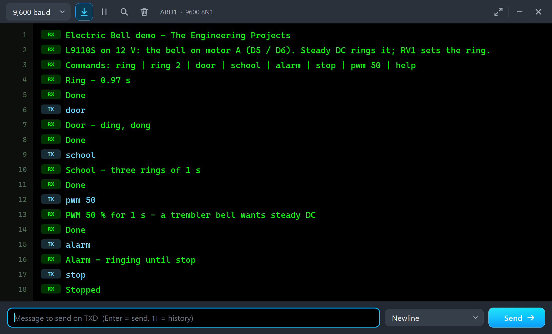
On the sheet, the hammer rattles against the gong, rings spread around its rim and the COIL LED lights. The pop-up's Event log writes "RINGING - 25.7 strikes a second at 11.3 V across the bell" after the fifth strike and, when the sketch switches it off, "STOPPED - rang 0.93 s, 25 strikes (25.7 a second)" - a touch under the 0.97 s of power the sketch gave it, because the hammer needs a moment to travel before its first strike. The 11.3 V is what is left of the 12 V supply after the L9110S's output switches, and the current peaked at 453 mA.
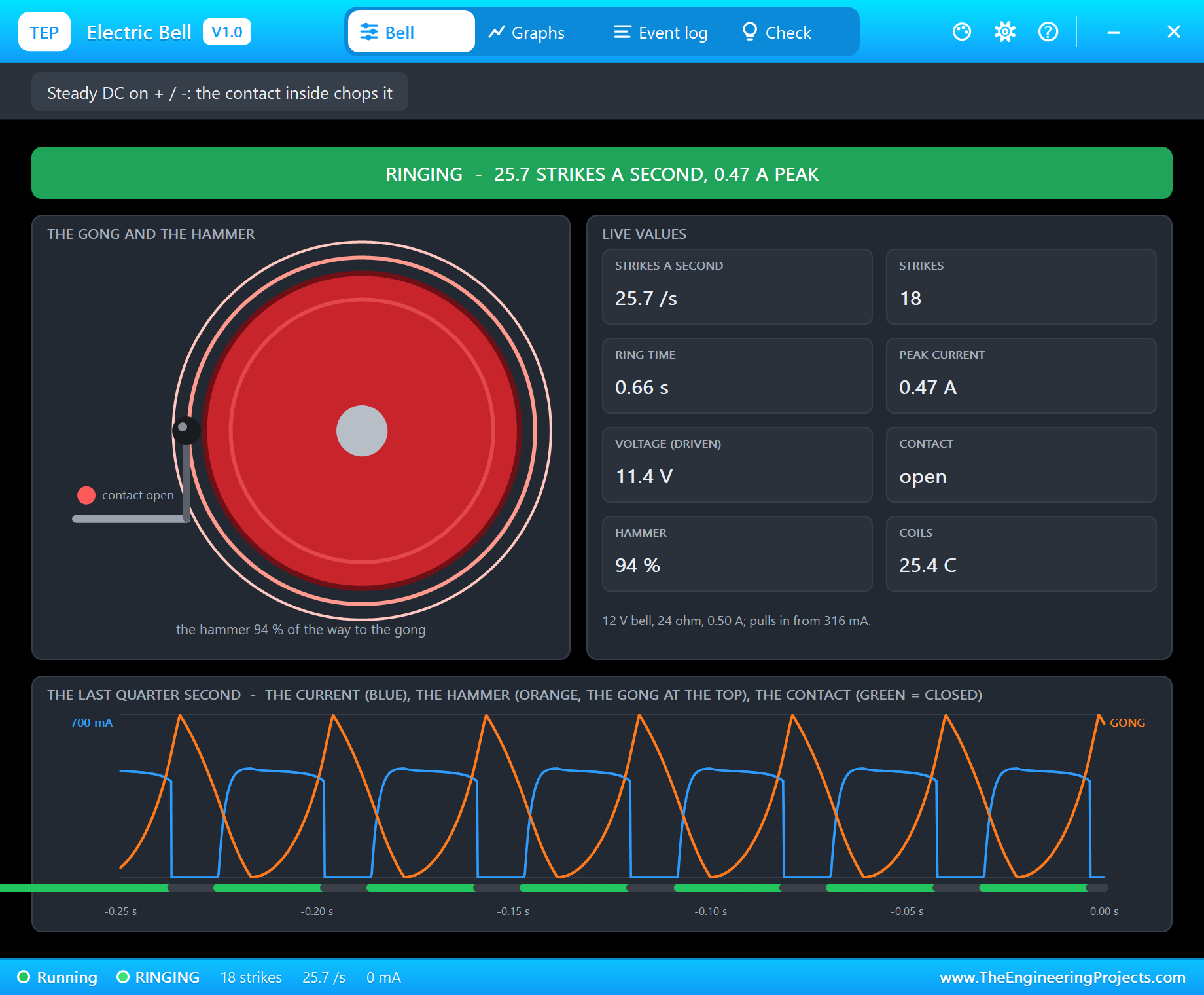
The pop-up has the look of our TEP Serial Monitor Advance for Proteus and four tabs: Bell, Graphs, Event log and Check. The Bell page shows the state in big letters - here "RINGING - 25.7 STRIKES A SECOND, 0.47 A PEAK" - then the gong and the hammer, with a dot that is green while the contact is closed and red while it is open. Next to them are eight live values: the strikes a second, the strikes, the ring time, the peak current, the voltage while driven, the contact, the hammer's travel and the coils' temperature.
The bottom of the page is the best part: the last quarter second, drawn like an oscilloscope. The orange line is the hammer, with the gong at the top, so each peak is a strike. The blue line is the current: it climbs as the contact closes - slowly, because the coils are an inductor - and drops to zero the moment the contact opens. The green bar under them is the contact itself. The whole trembler cycle is there: the contact opens on the way in, the hammer strikes a moment later, and the current comes back as the hammer returns.
A Doorbell and a School Bell
Type door. The sketch plays the classic ding-dong - two rings of 150 ms with 350 ms between them:
door
Door - ding, dong
Done
Each short ring gets four strikes: "STOPPED - rang 0.12 s, 4 strikes (25.7 a second)", twice. The log writes no RINGING line for them, because the bell only calls it ringing after the fifth strike, and a short ring is over before that. Now type school:
school
School - three rings of 1 s
Done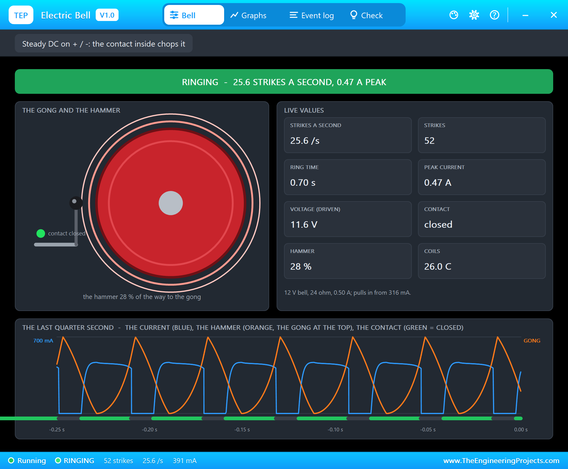
Three rings of 1 s, each logged on its own: 25.7, 25.6 and 25.6 strikes a second and 26 strikes each. The rate holds steady from ring to ring because the supply does - a trembler bell's speed is set by its spring, its hammer and its voltage, not by the sketch.
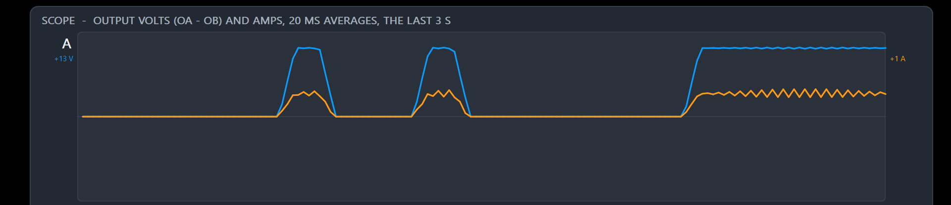
The L9110S's pop-up sees the same rings from the driver's side. Its scope shows motor A's output voltage in blue and its current in orange, in 20 ms averages: the two short pulses of the doorbell, then the school ring starting. The voltage stays flat at the top, but the current ripples - that is the bell's contact opening and closing twenty-five times a second, as the driver sees it.
PWM: Why the Bell Stays Silent
Now the classic mistake. Many sketches drive every load with analogWrite(), and it seems natural that a bell should ring louder or softer with the duty. Type pwm 50: the sketch drives D5 with a 50 % PWM for one second:
pwm 50
PWM 50 % for 1 s - a trembler bell wants steady DC
Done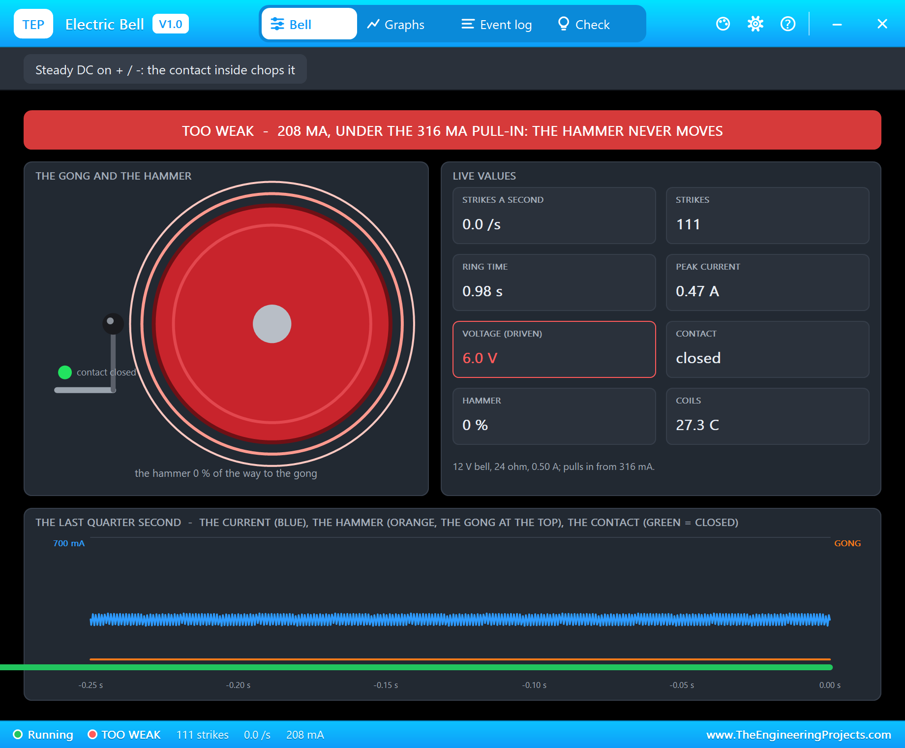
Nothing rings. Pin 5 of the UNO switches at about 977 Hz, far faster than the coils can follow, so their current settles at the average, and the log says "TOO WEAK - 219 mA through the coils, under the 316 mA pull-in: the hammer never moves". The armature never leaves its spring, so the contact never opens either: the current just sits there, a steady 0.2 A of heat. The Bell page shows the voltage while driven as 6.0 V, in red. Just before that line, the log has already caught the PWM itself: "a PWM drive (about 974 Hz): a trembler bell wants steady DC - its hammer weakens".
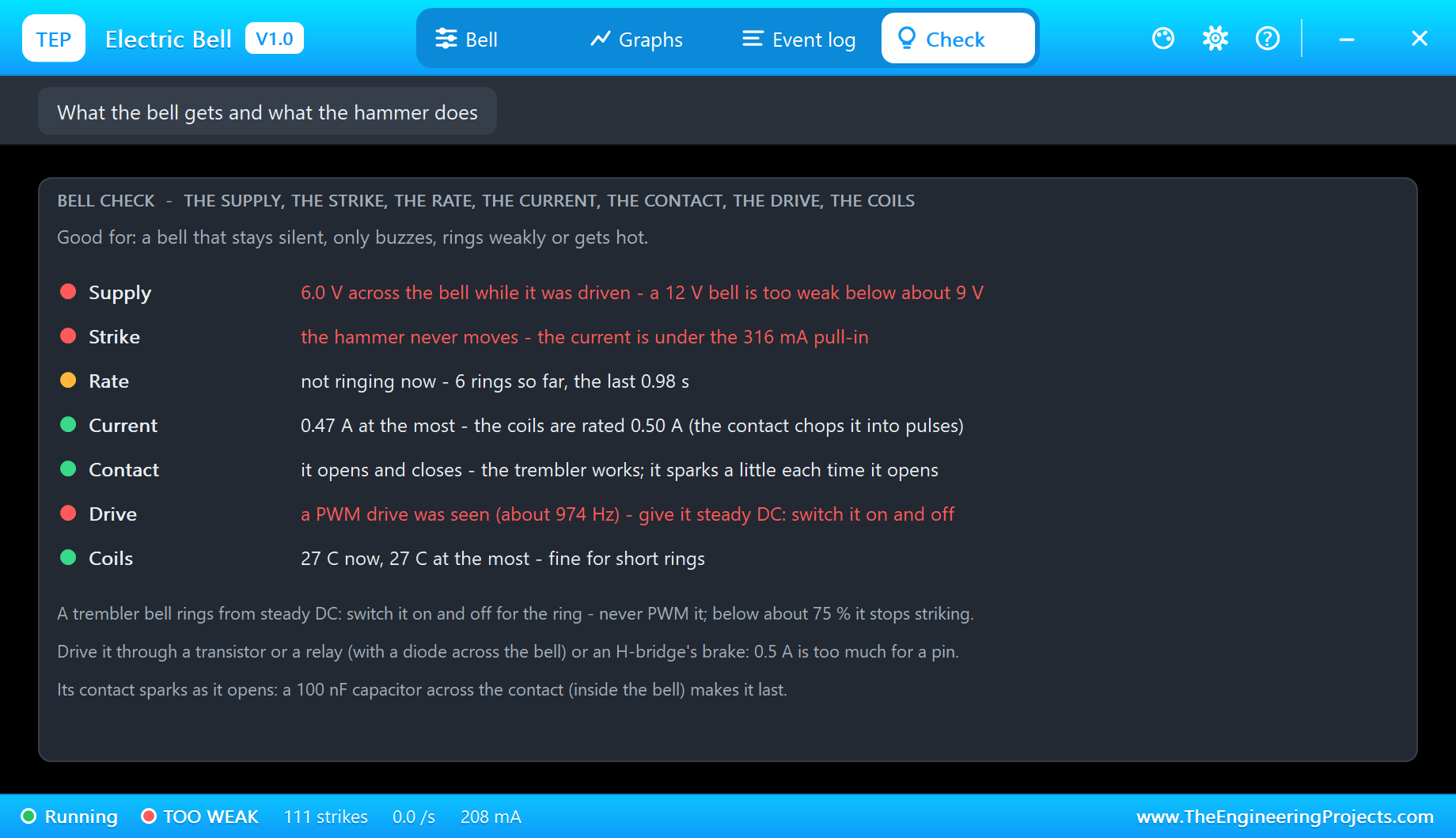
The Check page goes through the supply, the strike, the rate, the current, the contact, the drive and the coils, each with a coloured dot. During the PWM it reads "6.0 V across the bell while it was driven - a 12 V bell is too weak below about 9 V", "the hammer never moves - the current is under the 316 mA pull-in" and "a PWM drive was seen (about 974 Hz) - give it steady DC: switch it on and off". Its tips say the rest: a trembler bell rings from steady DC, and below about 75 % PWM it stops striking.
Higher duties do not really help either. In our tests, an 85 % PWM still rings the bell, but weaker and slower - 21 strikes in a second instead of 26. A trembler bell has its own switch inside; all it wants from the sketch is on and off.
An Alarm
Type alarm, and the bell rings until you type stop:
alarm
Alarm - ringing until stop
stop
Stopped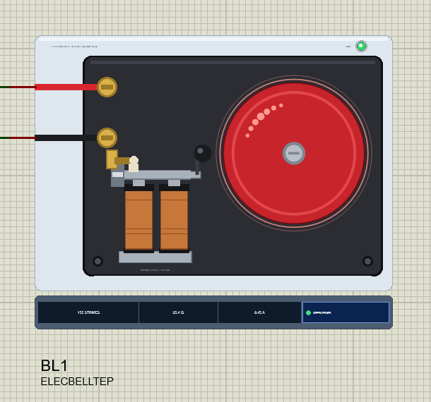
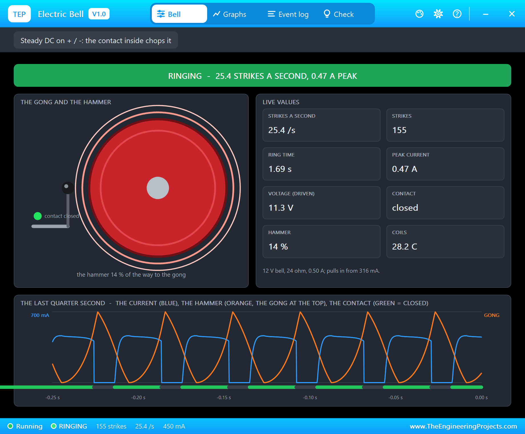
The log reads "RINGING - 25.5 strikes a second at 11.3 V across the bell", and at the stop "STOPPED - rang 2.56 s, 66 strikes (25.4 a second)". The rate falls very slightly over a longer ring, because the coils warm up and their resistance rises. The whole run, 177 strikes, took the coils to 29 C. A minute of ringing would take them to about 50 C, which is why the Check page and the Graphs page keep an eye on them: real bell coils are made for rings of seconds, not minutes.
Graphs and the Log
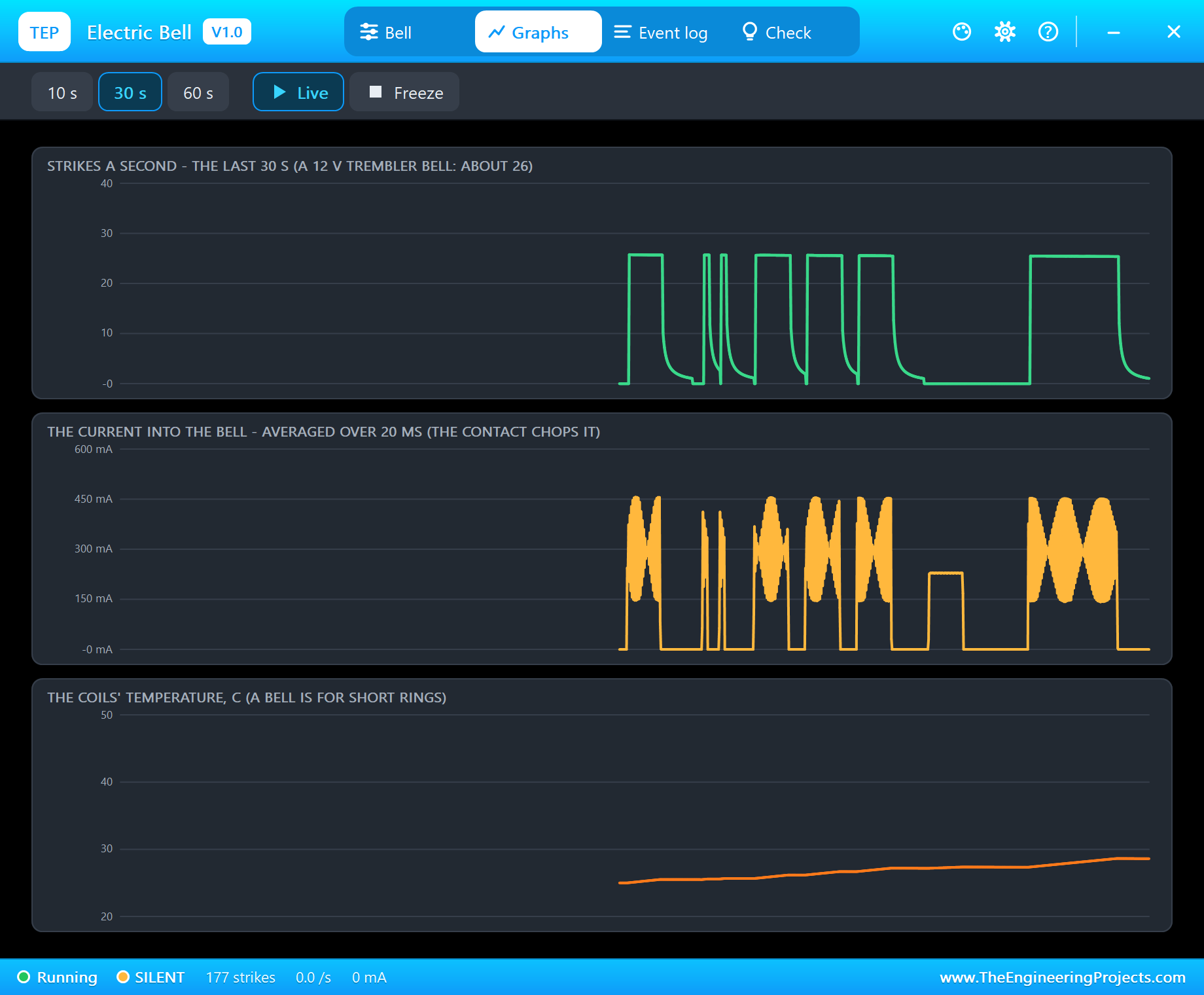
Graphs draws the strike rate, the current into the bell and the coils' temperature over the last 10, 30 or 60 seconds. Over 30 s it tells the story of the whole demo. The rate graph shows the power-up ring, the two short door rings, the three school rings and the alarm. The current graph shows the trembler's pulses beating against its 20 ms averages, and the flat block of the PWM test, where current flowed but nothing struck. The temperature graph climbs slowly from ring to ring.
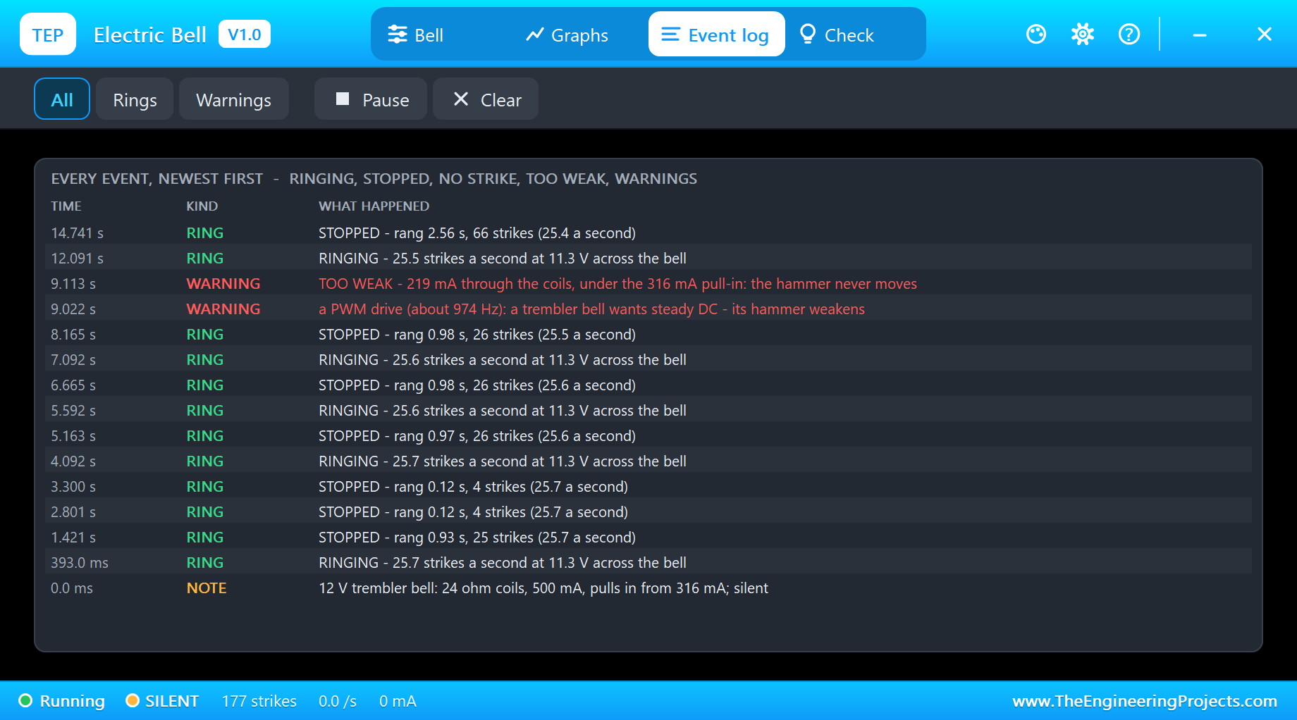
The Event log keeps every ring with its rate and voltage, every stop with its length and strikes, and every warning with its reason. Filter it to Rings or Warnings, pause it, or clear it.
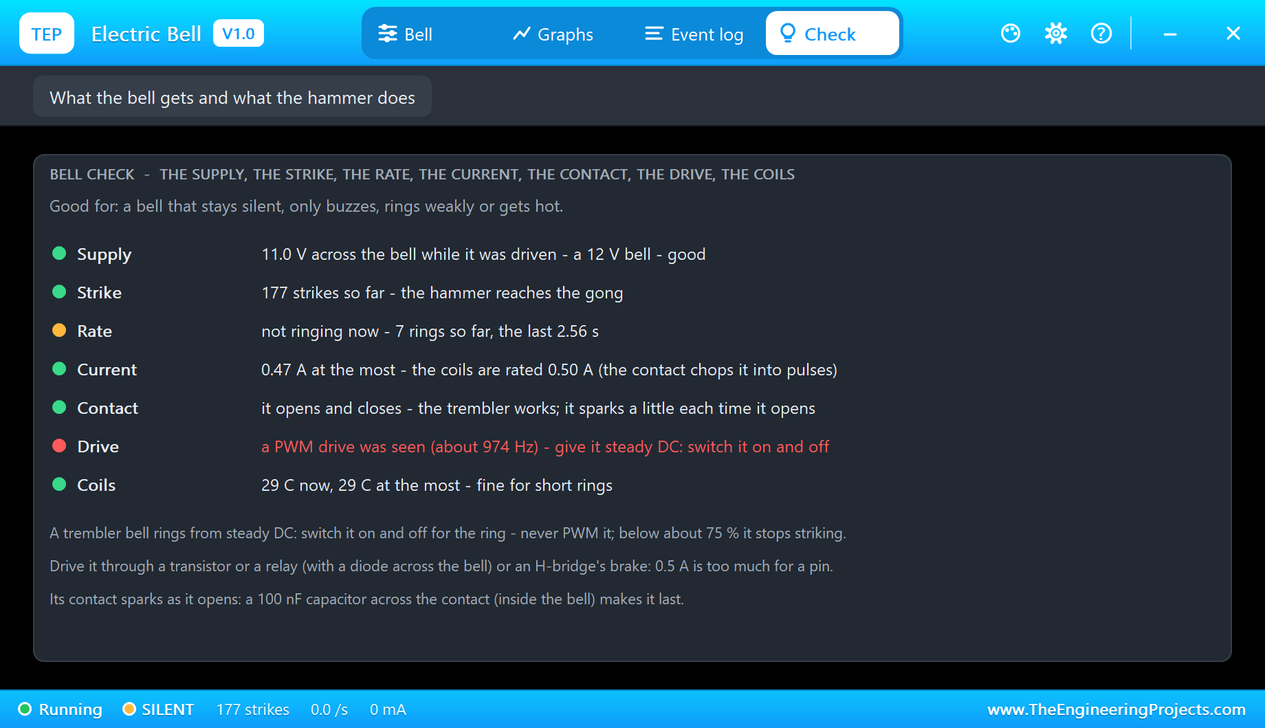
The Check page after the run: 11.0 V across the bell while it was driven, good for a 12 V bell; 177 strikes, so the hammer reaches the gong; seven rings, the last 2.56 s; 0.47 A at the most, under the 0.50 A rating; the contact opening and closing; and the coils at 29 C. Only the Drive row stays red, because the PWM test happened - the page remembers it, so you cannot miss it.
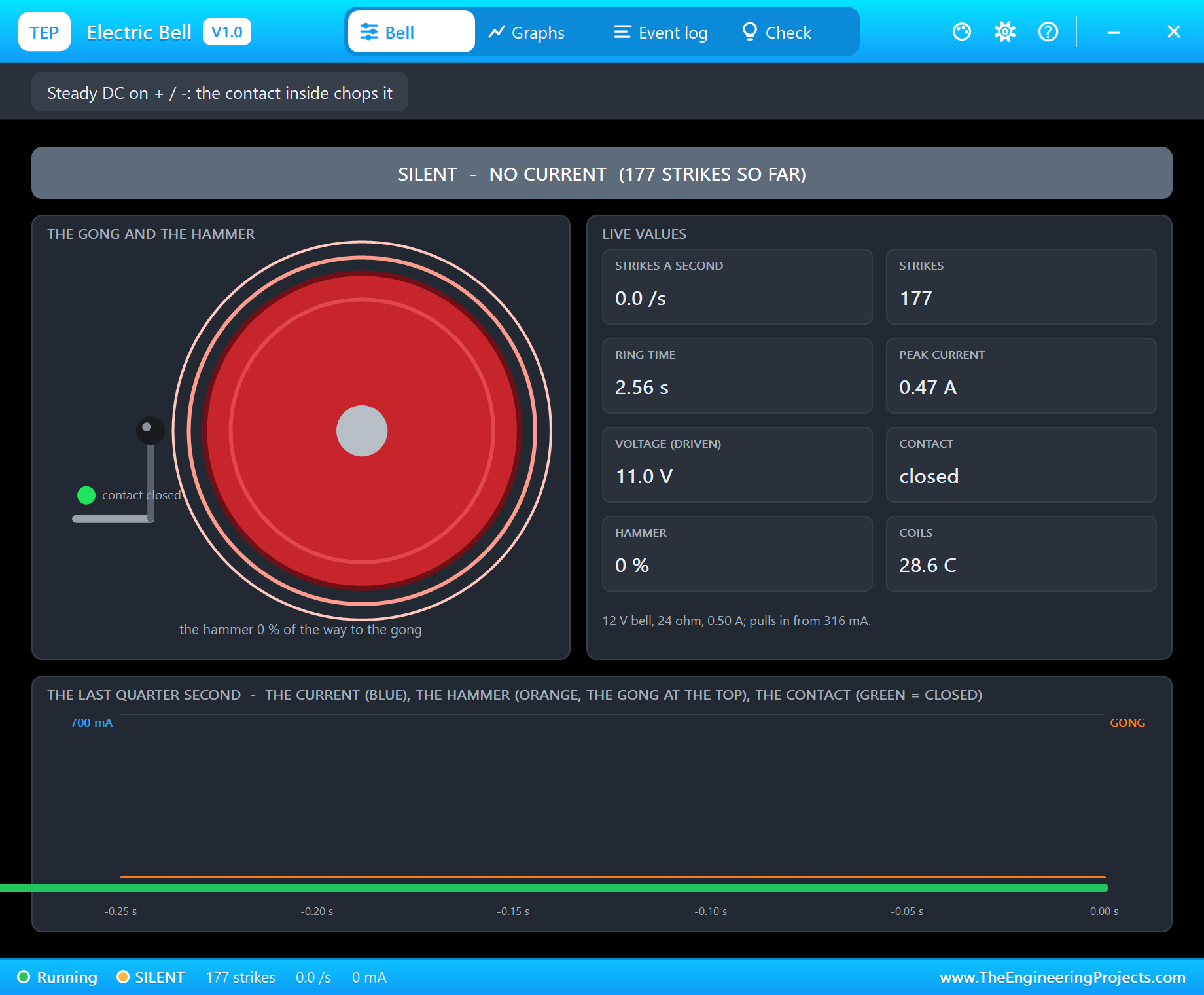
Once the alarm stops, the Bell page goes back to SILENT and the hammer to its rest, while the gong's rings die away over about half a second.
How the Model Works
While the contact is closed, the coils are in the circuit between + and -. Their inductance depends on the gap at the pole - 36 mH with the armature open, 103 mH with it at the pole - so the model works with the magnetic flux in the coils rather than their current: at every analog step it puts a conductance and a source into the circuit that follow the armature. The coils' resistance is 24 ohm at 25 C and rises by 0.393 % a degree. While the contact is open, the terminals carry only a tiny leak, and the current left in the coils dies inside the bell, through the contact's spark and its suppressor.
The armature and the hammer are a 40 g mass on a spring of 0.25 N plus 40 N/m, with a little friction and damping. The magnetic pull comes from the same inductance: it grows with the square of the current and steeply as the gap closes, which is why the armature, once it starts, slams in. The hammer bounces off the gong with a restitution of 0.35, a strike counts when the hammer hits faster than 5 cm/s, and the gong's ring dies away in 0.6 s. The armature, the contact and the coils' internal current run in 10 us sub-steps between the analog points, which are held to 50 us while the bell is driven or moving and to 2 ms at rest.
We checked the model on a PC with 13 automatic tests: 12 V for 2 s gives 26.0 strikes a second with 0.48 A peaks; the bell rings at 11, 10, 9 and 8.5 V and stays silent from 8 V down; 6 V is TOO WEAK; 24 V on a 12 V bell gives 0.93 A and the over-current warning, while a 24 V bell rings normally on 24 V; a 50 % PWM never strikes and its frequency is read; a ding-dong is two rings; three school rings are each logged at the true rate; and a 60 s ring warms the coils to 50 C. The demo project is read back from disk with 57 checks.
Troubleshooting
- It stays silent and nothing is logged: no current - the L9110S has no 12 V, or its inputs are not driven.
- TOO WEAK: the supply is too low for the bell (a 24 V bell on 12 V), or a PWM averages it down. Give it its rated voltage, steady.
- NO STRIKE: the contact chops but the hammer stops short of the gong - more voltage, steady DC.
- It rings fast and the coils get hot: a 12 V bell on 24 V - set VOLTAGE to 24, or lower the supply.
- The bell is not simulated:
TEPBELL.DLLis missing from MODELS and from the project folder. - No driver: install our L9110S library (
TEPL9110S.LIBandTEPL9110S.DLL). - No UNO or no monitor:
TEPARDUINO.DLLis missing; a closed monitor opens again with a click on the UNO's USB port. - No pop-up: click OPEN PANEL on the strip, or turn "Open the panel at Run" back on in its Settings.
Things to Know Before Wiring a Real Bell
- Use a driver: a 12 V trembler bell takes 0.3 - 0.5 A. Switch it with an NPN transistor or a logic MOSFET with a diode across the bell, a relay, or an H-bridge - never straight from a pin.
- Steady DC, never a PWM: switch it on for the ring and off for silence. Its own contact does the chopping.
- Look after the contact: it sparks every time it opens. A 100 nF capacitor across the contact, inside the bell, makes it last much longer.
- Set the gap: the adjusting screw sets the contact gap. Too far and the bell only buzzes; too close and the contact never opens.
- Ring in short bursts: the coils are made for seconds, not minutes - long alarms are better as repeated rings with pauses.
Limitations of the Simulation
- Not modelled: the sound itself, AC operation, the wear of the contact, single-stroke bells and motor-driven bells.
- The plate, the COIL LED, the rating line and the strip are TEP additions.
- The model is our own, written from the typical data of 12 V DC trembler bells; this library is not made or endorsed by any bell maker, Arduino or Labcenter.
- Licences: the demo HEX contains the Arduino AVR core 1.8.6 (LGPL); the sketch is included and the README gives the source link. The L9110S driver of the demo is our separate library.
- Tested in Proteus 8.5 in October 2026 with the demo as shipped: the power-up ring, the doorbell, the school bell, the PWM test, the alarm and all four pages of the pop-up. Proteus 7 is not supported.
So, that was all about the Electric Bell Library for Proteus V1.0. I hope it helps you with your school bell timer, your doorbell or your alarm project, and saves you from the bell that only hums because a sketch tried to PWM it. If you have any questions, ask in the comments and I will help you out. Till the next tutorial, take care and have fun!