Capacitance Measurement using Arduino
Hello geeks, welcome to our new project. In this project, we are going to make a very useful and interesting electronics tool that we as engineers or tinkers need in everyday life. We use the capacitor in most of our projects for various purposes such as filters or power supplies. Most of the time, we do not have a provision to measure the capacitor value in our digital multimeter. So, this time we came up with the solution. Hence, we will make our own capacitance measurement tool using Arduino.
Rather than investing in new electronic equipment, we will use an Arduino board and some basic components to measure the capacitance. To make this project, we should have some working knowledge about the capacitor. Here, we will not discuss the in-depth working of capacitors, but we will talk briefly so that it would be easy to understand the working principle of our project.
The capacitor is an electronic component that basically stores the energy when applied to an electric field. It has two parallel terminals connected by two parallel conducting plates separated by a dielectric material. Dielectric materials are electrical insulators(resist to pass the current) that can be polarised by applying an electric field. When we connect a battery with the capacitor then due to potential difference, the electric field is created between two oppositely charged plates of the capacitor and this way the capacitor stores the energy.
| Where To Buy? |
|---|
| No. | Components | Distributor | Link To Buy |
| 1 | Capacitor | Amazon | Buy Now |
| 2 | Resistor | Amazon | Buy Now |
| 3 | LCD 16x2 | Amazon | Buy Now |
| 4 | Arduino Uno | Amazon | Buy Now |
Software to install
To make this project, we will need some software to install. As we will make our project in the simulation, so for that we will install Proteus simulation software and for coding, we will use the Arduino IDE.
A brief about Proteus, it is a tool used for simulation and design of electronic circuits. Here we can design different types of electronic circuits and run the simulation. Although Proteus has a very big database for electronic components, still we need to install some libraries which we will use in this project.
- Arduino UNO - We have to install the library for Arduino UNO.
- LCD module - We have to install a library for the LCD module.
You can download this whole project for example Proteus Simulation and Arduino Code, by tapping the below button:
Capacitance Measurement using Arduino
Project overview
In this project, we will use the following components-
- Arduino UNO - We will use this as the main controller for this project. It will calculate the capacitance of the capacitor.
- 16x2 LCD Module - We will use this to show the result of measured capacitance and some user-related messages.
- Resistors and Capacitors - We will be using some resistors to make the RC circuit which is required for measuring the capacitance.
Now let's talk about the working of this project. The capacitance of any capacitor is the amount of charge that is stored in that capacitor and its unit is Faraday (F). To measure the capacitance, we will use some basic properties of the capacitor.
So when we connect a power supply with a resistor across the terminals of a capacitor, it will take a certain amount of time to fully charge. And when we connect any discharging resistor as a load across it, then it will take a certain amount of time to fully discharge. And this charging and discharging time will be proportional to the capacitance of the capacitor and the charging resistor in the RC circuit.
We will use the time constant formula for the calculation of capacitance. The time constant of any capacitor is known as the time taken by the capacitor to charge 63 percent of applied voltage or the time taken by the capacitor to discharge to 33 percent of stored voltage.
Here,
T (Tau) = Time constant(Seconds)
R = Resistance (Ohms)
C= Capacitance (Farads)
Using the above principle, we will charge the capacitor using a resistor to reach the charge of the capacitor to 63 percent of applied voltage and we will measure the time taken by the capacitor to reach that point. As we know the resistor’s value and time constant, using these two, we can calculate the capacitance:
Components required
- Arduino UNO
- 16x2 LCD module
- 10 kOhms Resistor
- 220 Ohms Resistor
- An unknown capacitor(Enter range here )
Components details
1. Arduino UNO
- Arduino UNO is an open-source development board that will be used to measure capacitance.
- It comes with 14 digital I/O pins and 6 analog I/O pins.
- It has 1 UART, 1 SPI, and 1 I2C hardware which are multiplexed with GPIO pins.
- Digital pins can be used for input and output for digital data. In this project, we have used digital pins for charging the capacitor.
- Analog pins have 10 bits of ADC (Analog to Digital convertor) resolution ranging values from 0 - 1023.
- Analog pins can be used for input and output purposes. In this project, we have used analog pins as input for measuring the discharge and charge voltage.
Note-Whenever uploading the code on the Arduino UNO, disconnect any wire which is connected to Rx(D0) and Tx(D1) pins, otherwise, it will give an error while uploading the code.
2. LCD Module
- LCD stands for Liquid Crystal Display, and its display is made using liquid crystal technology.
- For more knowledge of how LCD works, prefer this link Working of LCD display.
- We have used a 16x2 LCD display in this project.
- The LCD module works in two different data modes: 8-bit or 4-bit mode.
- We have used 4-bit mode which means we can send 4-bit data in a single cycle to the LCD module.
- We have used an LCD module to display the user-related information such as capacitance value and the welcome message.
3. Resistors and Capacitors
- Resistors, as the name suggests, is an electronic component that controls the flow of current in a circuit.
- Current flowing in any circuit is inversely proportional to resistance.
- They are used mostly in every type of electronic circuit for current limiting, voltage divider, and in some noise filters.
- There are various types of resistors available depending upon the current rating, manufacturing materials, and use case.
- Although we are making this project in simulation, if you want to make this project using the real components for that we will use the carbon composition through-hole resistors.
- Capacitors are electronic components that have the ability to store energy.
- When we connect any battery across the terminals of capacitors then it will start charging.
- We can store a large amount of charge for a very short period of time in capacitors.
Circuit diagram and Working
Now, we have a list of all the required components. Let's start connecting them.
- Make sure, we have the correct version of Proteus and have installed all the required libraries which we will be using in this project.
- Now let’s start creating the new project in the Proteus.
- Import the listed components to the workspace of Proteus.
- Now we have imported all the components to the workspace.
- First, connect the charging resistor of 10K ohms with the digital pin 8 of Arduino UNO and then connect the discharging resistor of 220 ohms with the digital pin 9 of the Arduino UNO.
- We will use the D8 pin for charging the capacitor and the D9 pin for discharging the capacitor.
- Now connect the capacitor which we want to measure in between these two resistors and connect another terminal of the capacitor with the ground.
- Connect an analog pin of Arduino UNO with the discharging resistor terminal and that analog pin will be A0 on Arduino UNO.
- After that, we are finished with our RC circuit.
- Let’s connect the LCD module with the Arduino UNO, as we are using the LCD module in 4 bits mode so we need to connect only four data pins with Arduino UNO.
- Connect D4 pin to D7 pins of the LCD module with D2 to D5 pins of the Arduino UNO.
- While connecting them, keep in mind that they must be connected in the same order.
- Connect the RS pin with the D6 and Enable pin with the D7 pin of Arduino UNO.
- Connect the RW pin with the ground which enables the write mode in the LCD module.
- Connect the 5v power supply with Vdd and Gnd pins of the LCD module.
- Now we have connected all the components.
- Before moving to the coding part, reverify your connections once.
While working on the real components, make sure you have connected the backlight of the LCD module and set the contrast properly otherwise nothing will be visible on the LCD module.
Arduino code of Capacitance measurement-
Downloading and including libraries
- This project will need the library for the LCD module.
- Before going to write, we must download and include all the required libraries.
- We can download the library for the LCD module using this link LCD module library.
- To include the library, go to the Sketch >> Include Library >> Manage Libraries… Using this, we can add libraries directly by searching the window.
- Or if you have downloaded the library using the link then you will have a zip file for the library. In this case, follow this path: Sketch >> Include Library >> Add .Zip Library…
- After downloading the library, we are all set to start our code.
- First, include the LCD library header at the start, make an object for the same, and declare all the pins which are used for the LCD module.
Variable declaration
- Now we will declare all the variables and pins which we are going to use in this project.
- Declare the charging pin, discharging pin, and an analog pin for measuring the charging voltage as 8,9 and A0 respectively.
- Declare variables to store the start time, stop time, and a variable to store the duration.
- Declare a function “measure()” which will read the analog values.
- After the declaration, we will define a function “measure()”.
- We have defined this at the end of the code.
- This function will read the analog values from the pin and return the values for the same.
- Here, we have declared and defined the function separately but we can define the function without declaring it, but it is not a good practice to do so and sometimes that will cause errors in the code also.
Void setup()
- After declaring all the required variables, we will start writing the “void setup()” function.
- This is a built-in function in the structure of the Arduino sketch.
- We can write any code without this function. As per the structure of the Arduino sketch, this function must be in the code.
- In this function, we will write the pin mode and initialization of other peripherals which will be required in the code.
- This function will only run once when the code starts.
- So in this function, we will first begin the LCD module and print the instructions to use.
- Then set the pin mode of pins and the initial state of the pins.
Void loop()
- This is also a built function of Arduino sketch.
- As per the structure of the Arduino sketch, we can not delete this function from the code even though we don’t have anything to write in this.
- This function executes after the “void setup()” function.
- In this function, we will write our main code which we want to run continuously.
- As the name suggests this will run in a loop.
- Initially, when there is no capacitor connected then the analog value will be in the maximum range and that is 1010 to 1030.
- So now, we will display the message that ‘place a capacitor’ and code will be in a while loop until we connect any capacitor to the circuit.
- Now when we connect any capacitor, the above condition will be unsatisfied, then code will enter in a next infinite while and there we will write the process of charging and discharging of capacitor and time constant.
- First, we will discharge the whole capacitor, for that we will run a while loop, and using the measure() function, we will measure the currently stored voltage in the capacitor.
- And when the stored voltage reaches below or equal to the threshold, we will change the pin mode of pins to start charging the capacitor again and store the start time of charging.
- Using the measure() function, monitor the charging voltage in the capacitor and when the stored charge reaches 63 percent which is 648 of 1023 then we will stop the charging and store the stop charging time also.
- And display the charging percent on the LCD module.
- Now calculate the total time taken by the capacitor to reach the 63 percent of charge and that will be the time constant of the capacitor.
- Using the time constant formula, we can calculate the capacitance of the capacitor as we know the charging resistor connected to the capacitor.
- As we know the charging resistor value is 10k ohms, using that when we divide the time taken by the resistor value, then we will get the capacitance.
- And the calculated result will be displayed on the LCD module for 3 seconds, after that code will enter in an infinite while loop.
- Now we have to reset the device to measure any new capacitor value.
- Here, our coding part will be completed, it is time to test our code with the circuit and now we will move to the next section.
Results and Working
- As we are going to test our project in the Proteus simulation, we have to include the hex file of our code in the Arduino UNO module.
- The first step is to generate the hex file of the code.
- Click on the Arduino UNO module in the Proteus then browse to the location of the generated hex file.
- After adding the code, we are ready to run the simulation and click on the Play button to start the simulation.
- First of all when the code starts, on the LCD module, we will show the range of capacitance that can be measured using this device and the message to place the capacitor if it is not placed already.
- When the capacitor is placed, then the discharging process will start to eliminate any pre-stored charge in the capacitor, thus we will get the more accurate value.
- After 100 percent discharge, the charging process will start and it will go to 63 percent of the stored charge.
- Thereafter, the code will calculate the capacitance using the time constant formula, and the result will be displayed on the LCD module with the message to reset the device to measure again.
- After the compilation of the simulation, click on the stop button to stop the running code.
I hope we have covered all the points related to this project such as circuit diagrams, codes, and working simulation. And I think this will be a very useful project for your daily tinker life. Please let us know if you face any difficulties while making this project in the comment section below.
We will be happy to hear if you will make this project used in your projects.
Thanks for reading this article. All the best and see you in the next project.
2 Relay Module Interfacing with Arduino
Hello everyone! I hope you all will be absolutely fine and having fun. Today, I am going to provide a detailed discussion on
2 Relay Module Interfacing with Arduino. First of all I would like to explain you that
what is relay and how to use it and then we will move forward towards 2 relay module interfacing with Arduino. I have already controlled
relay with 555 timers. 2 relay module consists of two relays. Relay is basically an electronic device or a switch which is used to open and close the circuits electronically.
A relay controls an electric circuit by opening and closing contacts in another circuit. When the relay contact is normally open (NO), there will be an open connection when the relay is not energized. When the relay contact is normally closed, there will be a closed connection even when the relay is not energized. We can use relays to control the smaller currents in different electronic circuits. 2 relay module has two relays. One relay can control two AC/DC device simultaneously. That means 2 relay module can control four AC/DC devices at a time. 2 relay module is normally used to control the DC motors in different projects e.g. robotics, automation, embedded projects etc. It can control two DC motors simultaneously. Moreover, we can also use it for different applications e.g. to control DC/AC fans, AC/DC lights, AC/DC bulbs and a lot more. The further detail about 2 relay module interfacing with Arduino will be given later in this tutorial.
2 Relay Module Interfacing with Arduino
2 Relay Module is an electronic device consists of two relays as its major components. Relay is a switch which makes or loses the connection between two different circuits. A single relay is capable of controlling two AC/DC devices simultaneously. So, 2 relay module is able to control four AC/DC devices at the same time. Mostly it is used to control the DC motors. It can also be used in different projects e.g embedded projects, robotic, automation, power etc. 2 relay module is shown in the figure given below.
1. Relay Proteus Simulation
2. 2 Relay Module Components
- A complete list of the components used while designing 2 relay module is shown in the figure given below.
3. 2 Relay Module Input Pins
- 2 relay module has five (5) input pins in total, each perform different action.
- All of its pins are provided in the table shown in the figure below.
4. 2 Relay Module Input Pins Description
- We must know about the functions of each pin.
- 2 relay board/module input pin functions are listed in the table shown in the figure below.
- Both IN1 and IN2 comes from the micro-controller (Arduino UNO in this case).
- IN1 pin controls the 1st relay attached on 2 relay module.
- IN2 pin controls the 2nd relay attached on 2 relay module
5. 2 Relay Module Output Pins
- 2 relay module has three (3) output pins for each relay.
- Its output pins are given in the table shown in the figure given below.
6. 2 Relay Module Output Pins Description
- Each output pin of 2 relay module has its own functions.
- 2 relay module pin functions are listed in the table given in the figure shown below.
- NO pin is normally open pin and device attached to this pin will not work if the relay is not energized.
- COM is a common pin i.e. ground pin.
- NC is normally closed pin and device attached to this pin will start working even if the relay is not energized.
7. 2 Relay Module Compatibility
- 2 relay module is compatible with different micro-controllers.
- Some of those micro-controllers are provided in the table shown in the figure given below.
8. 2 Relay Module Circuit Diagram
- Circuit diagram of 2 relay module is given in the figure shown below.
9. 2 Relay Module Interfacing with Arduino Wiring Diagrams
10. 2 Relay Module Interfacing with Arduino Actual Diagrams
- I have provided the complete wiring diagram for 2 relay module interfacing with Arduino.
- Wiring diagram is shown in the figure given below.
11. 2 Relay Module Interfacing with Arduino Source Code & Description
- If you are new to Arduino software then you must have a look at How to write Arduino code.
- You just need to copy and paste the source code given below in your Arduino software.
- The complete source code for 2 relay module interfacing with Arduino is given below.
int relay1 = 6;
int relay2 = 7;

void setup() {

  pinMode(relay1, OUTPUT);
  pinMode(relay2, OUTPUT);
}

void loop() {

   digitalWrite(relay1,LOW);
   delay(1000);

   digitalWrite(relay1,HIGH);
   delay(1000);

   digitalWrite(relay2,LOW);
   delay(1000);

   digitalWrite(relay2,HIGH);
   delay(1000);
}
- First of all I have defined relay pins.
- Then I have changed the mode of these pins to output.
- After that I have turned on and off both of the relays with the delay of 1 sec or 1000 msec.
- So, that was the brief description about the source code for 2 relay module interfacing with Arduino.
- You can download the wiring diagram and complete Arduino source code here by clicking on the button below.
12. 2 Relay Module Features
- The most common features associated with 2 relay module are provided in the table shown in the figure given below.
13. 2 Relay Module Application
- 2 relay module applications are given in the table shown in the figure below.
In the tutorial
2 Relay Module Interfacing with Arduino, we have learnt about the components used in the design of 2 relay module. We have also learnt about the 2 relay module interfacing with Arduino. I have provided the complete Arduino source code, you can control this module using the same code. I hope you have enjoyed the tutorial. If you have any problem you can ask us in comments. Out team is 24/7 available for you. I will share different informative engineering topics in my upcoming tutorials. So, till my next tutorial, take care and bye :)
Stepper Motor Speed Control using Arduino
Hello everyone! I hope you all will be absolutely fine and fun. Today, I am going to tell you that how to make a simple algorithm for
Stepper Motor Speed Control using Arduino. I have already discussed with you about
DC Motor Direction Control using Arduino,
Matlab and NI LabVIEW. Moreover, I have also discussed the
DC Motor Speed Control using Arduino,
Matlab and LabView. If you are working on Stepper Motor, then you must have a look at
Stepper Motor Direction Control using Arduino,
Stepper Motor Direction Control using Matlab and Stepper Motor Direction Control using NI LabVIEW. Now, in this tutorial I will explain you about the program which will helpful for Stepper Motor Speed Control using Arduino. Before going into the details of this tutorial you must have go through my previous tutorials because I am using the same hardware. So, they will be a lot helpful for the better understanding of this tutorial.
In this tutorial I will explain you about making an Arduino program for
Stepper Motor Speed Control using Arduino with the help of the serial communication. If the stepper motor is rotating at its maximum speed and you are continuously sending the command through the serial port to reduce its speed, it s speed will be reduced in proportion to the number of command sent through the serial port. Similarly the same procedure will be followed to increase the speed of the stepper motor.
Stepper Motor Speed Control using Arduino
In the tutorial Stepper Motor Direction Control using Arduino, I will explain you about making an algorithm to run the stepper motor at different speed. If the stepper motor is already running at its maximum speed and you want want to accelerate it further then nothing will happen to the speed of the stepper motor. If the stepper motor is rotating slowly and you enhance its speed, then the speed of the motor will increase in proportion to the number of accelerating command sent through the serial port.
- You can download the complete Arduino source code here by clicking on the button below.
Download Arduino Code
- Download .rar file, extract it and enjoy the complete source code.
Flow Chart
- I have made a flow chart so that you can easily understand the entire algorithm because sometimes it becomes difficult to understand the algorithm with the help of the source code.
- Flow chart for the Stepper Motor Speed Control using Arduino is shown in the figure below.
- First of all we need to start the serial port so that our communication could be started.
- Then there is a method to check the speed, if the speed is greater than the maximum speed of the stepper motor then the program will wait for the next command.
- If the stepper motor is not rotating with its maximum speed then we can increase its speed.
- Similarly if the minimum speed of the stepper motor is reached then the program will rotate for the next commands.
- If the minimum limit of the speed of the stepper motor is not reached then we have a option to reduce its further.
- At the end we should close the serial port so that exchange of unnecessary commands through the serial port could be avoided.
Block Diagram
- Block diagram will be helpful for use for the better understanding of the exchange of information.
- It tells us that how the information is exchanged sequentially among all the components used.
- Block diagram is shown in the figure below.
- Arduino UNO communicates with the L298 motor controller to control the speed of the stepper motor.
- L298 Motor controller manipulates the Arduino's commands and starts to control the speed of the stepper motor.
Arduino Code Description
In this section of the tutorial Stepper Motor Speed Control using Arduino, I am going to elaborate you about the Arduino source.
- I have made two different functions for increasing (accelerating) the speed of the stepper motor and for decreasing (deaccelerating) the speed of the stepper motor respectively.
- I have declared a variable named as count.
- In Accelerate function, you have to send the command H through the serial port to increase the speed of the stepper motor.
- In this function, I am continuously increasing the value of the count i.e as many times you send the command H the speed of the stepper motor will increase continuously.
- The source code of the Accelerate function is given below.
   void Accelerate_Motor()
   {
    count=count+10; //Speed will increase continuously as we continue to press H
    if (count>120)  //Speed must not be greater than 120
    {
      count=120;
      }
    Serial.println("Accelerating"); //printing on the serial port
    Serial.println("");//prints blank line on the serial port
    myStepper.step(stepsPerRevolution);//counter clockwise rotation
    myStepper.setSpeed(count); //Updating the speed of the motor
    lcd.setCursor(3,0);//setting LCD cursor
    lcd.print("Acelerating"); //printing on LCD
   }
- In Deaccelerate function, you have to send the command L through the serial port to increase the speed of the stepper motor.
- In this function, I am continuously reducing the value of the count i.e as many times you send the command L the speed of the stepper motor will reduce continuously.
- The source code of the Deaccelerate function is given below.
void Deaccelerate()
{
  count=count-10; //reducing the speed of the motor
  if (count<20) //speed of the motor must not be less than 20
  {
    count=20;
    }
  Serial.println("Deaccelerating"); // prints on the serial port
  Serial.println(""); //prints blank line on the serial port
  myStepper.step(stepsPerRevolution);
  myStepper.setSpeed(count); //Updating the speed of the motor
  lcd.setCursor(3,0);  //setting cursor on LCD
  lcd.print("Deaccelerating"); //prints the command on LCD
  }
- In the main source inside the loop I am calling both of these Accelerate and Deaccelerate functions.
- The executed commands will also be printed on the LCD (Liquid Crystal Diode).
- The main source code is given below.
#include <LiquidCrystal.h>//Library for LCD
#include <Stepper.h>     //Library for Stepper motor

const int stepsPerRevolution = 255;

// initialize the stepper library on pins
Stepper myStepper(stepsPerRevolution, 4, 5, 6, 7);
char data;
int count = 120;
//LCD pins assigning
LiquidCrystal lcd(8, 9, 10, 11, 12, 13);
void setup() {
  // set the speed at 60 rpm
  myStepper.setSpeed(60);
  // initialize the serial port:
  Serial.begin(9600);// rate at which the arduino communicates

lcd.begin(20, 4);//LCD type

lcd.setCursor(3,0);//setting LCD cursor and printing on it
lcd.print("Stepper Motor");
lcd.setCursor(6,1);
lcd.print("Speed");
lcd.setCursor(5,2);
lcd.print("Control");
lcd.setCursor(2,3);
lcd.print("via Arduino UNO");

delay(3000);

lcd.clear ();//Clearing the LCD screen

lcd.setCursor(0,2);
lcd.print("www.TheEngineering");
lcd.setCursor(4,3);
lcd.print("Projects.com");
}

void loop() {
  if(Serial.available())
  {
    data = Serial.read(); //Reading the data from serial port
  }

    if(data == 'C'){Clockwise();}      //Clockwise rotation
    if(data == 'A'){AntiClockwise();} //Anti-clockwise rotation
    if(data == 'S')                  //stopping the stepper motor
    {
      data = 0;
      lcd.setCursor(3,0);
      lcd.print("No rotation");
      Serial.println("No rotation");//print on the serial
      }
     if(data == 'H'){Accelerate_Motor();}
     if(data == 'L'){Deaccelerate();}
}
Complete Hardware Setup
- In this section of the tutorial, I will show you the complete hardware setup that I have used for this project.
- Hardware consists of 12V power supply, Arduino UNO, L298 motor controller.
- When you upload the code to the Arduino board the system will look like the figure shown below.
- When you press H to increase the speed of the stepper motor, the statement accelerating will be printed on the LCD.
- The printed executed command is printed on the LCD and is shown in the figure below.
- When you press L to reduce the speed of the stepper motor, the statement Deaccelerating will be printed on the LCD.
- The printed executed command is printed on the LCD and is shown in the figure below.
That is all from the tutorial Stepper Motor Speed Control using Arduino. I hope you all have enjoyed this tutorial. If you face any sort of problem regarding anything you can ask me anytime without even feeling any kind of hesitation. I will try my level best to solve your issues in a better way if possible. I will explore Arduino by making further projects and I will share them with all of you as well in my later tutorials. So, till then, Take Care :)
Stepper Motor Direction Control using Arduino
Hello friends! I hope you all will be absolutely fine and having fun. Today, I will elaborate you that how can we make a simple algorithm for
Stepper Motor Direction Control using Arduino. In my previous tutorials I made algorithm for
DC Motor Direction Control using Arduino,
DC Motor Direction Control using Matlab,
DC Motor Speed Control using Arduino and
DC Motor Speed Control using Matlab. Now, in this tutorial I will control a stepper motor using Arduino by entering the different commands through its serial port.
Before going into the detail of this tutorial, you must know the basic difference between stepper and DC motors. DC motors have only two input terminal one is positive and the other one is negative. You just have to provide the power supply and it will start rotating but this is not the case in stepper motor. The stepper motor which I will use in this tutorial, has six pins out of which four pins provide pulses or steps and the other two pins are power pins. So, in this tutorial I will control this six pins stepper motor using L298 motor controller and Arduino UNO board. Basically we can use stepper motor where precision is required. Stepper motor has wide range of applications e.g robotics, CNC machines, home automation etc. In simple word, we can say that stepper motor can be used where there is a need to move at particular angle. So, let's get started with Stepper Motor Direction Control using Arduino:
Stepper Motor Direction Control using Arduino
In this tutorial we will learn how to make a program for
Stepper Motor Direction Control using Arduino by sending dfferent commands from the serial port. First of all, I am going share the list of components used for this mini project.
- Arduino UNO
- Stepper motor (6 wire)
- L298 Motor Controller (H-Bridge)
- Voltage Regulator (7805)
- 1000uF
- Jumper Wires
- Solderig Iron
- Soldering Wire
I want to tell you a bit about the stepper motor because all the other components are discussed in detail in
DC Motor Direction Control using Arduino.
Stepper Motor
Basically, stepper motors are like the DC motors that rotate in discrete steps. They have multiple arranged coils and they are usually known as phases. Motor will rotate one step at a time if we energize each phase sequence. High levels of precision can be achieved by controlling the stepper motor with computer. Steppers motors are available in the market in many different sizes. The speed of the stepper motor is controlled by frequency of pulses generated. They have wide range of applications like hard disk drives, robotics, telescope, antenna, toys etc. A six wire stepper motor is shown in the figure below.
- You can download complete source code for Stepper Motor Direction Control using Arduino by clicking the below button:
Download Arduino Source Code
Selection of Wires
- I have used 6 wire stepper motor and each wire has its own function.
- I have first divided these six wires into two pair.
- Each pair is consisting of three wires out of which one wire is common and the other two generate pulses.
- The two pair of three wires are shown in the figure below.
- Then, I have chosen a common wire in each pair from which the resistance to the other two wires is common.
- I have checked the resistance from the common wire to the both of the other wires of the same pair.
- I found that the resistance from the common wire to both of the other wires is same.
- We can see in the figure above the blue, pink and white wires belong to the same pair out of which white is a common wire.
- Here is the screen shot of the figure when I found the resistance between white and blue wire and I found it to be 8.0 ohms.
- The screen shot of the above steps is shown in the figure below.
- After that. I checked the resistance between white and pink wire and found it to be 8.1 which is almost the same as 8.0 so, this shows that the white wire is common to both of the blue and pink wire.
- Here is the screen shot of the above step.
- Then I found the resistance between pink and blue wire and it was 15.6 which is exactly the double of the earlier resistance.
- It is shown in the figure below.
- I have connect the both common wires as shown in the figure below.
- Here's the video in which I have discussed it in detail How to identify the wires of Stepper Motor:
- The remaining four wires are used to generate pulses which are also know as steps
- I have connected theses four wires to the output pins OUT1, OUT2, OUT3 and OUT4 of the L298 micro controller.
- Input pins of L298 micro controller In1, In2, In3 and In4 are connected to the pin no 7, 6, 5 and 4 of the Arduino UNO's board respectively.
Note:
I have also controlled the stepper motor using PIC micro controller so I would suggest all of you to first go through that tutorial before going into the details of this tutorial.
Block Diagram
- I have made a simple block diagram for Stepper Motor Direction Control using Arduino, which will be helpful to clearly understand the algorithm and the assembling of the components of Stepper Motor Direction Control using Arduino.
- The screenshot of the block diagram is shown in the figure below.
- First of all we need a power supply to run the project properly.
- Arduino reads the commands from the serial port and sends to the L298 motor driver to rotate the stepper motor.
- The commands got printed on the LCD (Liquid Crystal Display).
Arduino Source Code Description
- The main function of the Stepper Motor Direction Control using Arduino is given below.
#include <LiquidCrystal.h>//Library for LCD
#include <Stepper.h> //Library for Stepper motor

const int stepsPerRevolution = 255;

// initialize the stepper library on pins
Stepper myStepper(stepsPerRevolution, 4, 5, 6, 7);
char data;
//LCD pins assigning
LiquidCrystal lcd(8, 9, 10, 11, 12, 13);
void setup() {
  // set the speed at 60 rpm
  myStepper.setSpeed(60);
  // initialize the serial port:
  Serial.begin(9600);

lcd.begin(20, 4);//LCD type

lcd.setCursor(3,0);//setting LCD cursor and printing on it
lcd.print("Stepper Motor");
lcd.setCursor(5,1);
lcd.print("Direction");
lcd.setCursor(5,2);
lcd.print("Control");
lcd.setCursor(2,3);
lcd.print("via Arduino UNO");

delay(3000);

lcd.clear ();//Clearing the LCD screen

lcd.setCursor(0,2);
lcd.print("www.TheEngineering");
lcd.setCursor(4,3);
lcd.print("Projects.com");
}

void loop() {
  if(Serial.available())
  {
    data = Serial.read(); //Reading the data from serial port
  }

    if(data == 'C'){Clockwise();}//Clockwise rotation
    if(data == 'A'){AntiClockwise();}//Anti-clockwise rotation
    if(data == 'S')//stopping the stepper motor
    {
      data = 0;
      lcd.setCursor(3,0);
      lcd.print("No rotation");}

}
- In the code given above we have first initialized the LCD and Stepper motor libraries.
- Then, I assigned stepper motor pins at which it is connected to the Arduino.
- After that I initialized the LCD pins at which it is connected to Arduino UNO.
- Then I have made three different if statements, C for the clockwise, A for the anti clockwise rotation and S for the no rotation.
- Then in the loop I called clock wise and anti clockwise functions whose source code will be give and explained below.
- Then, I cleared the serial data in order to stop the rotation of the motor.
- The source code of the clockwise function is given below.
void Clockwise()//function for clockwise rotation
{
    Serial.println("clockwise"); //printing on the serial port
    Serial.println("");//prints blank line on the serial port
    myStepper.step(stepsPerRevolution);//counter clockwise rotation
    lcd.setCursor(3,0);//setting LCD cursor
    lcd.print("Clockwise"); //printing on LCDa
}
- The source code for the anti clockwise function is given below.
void AntiClockwise()//function for anti clockwise rotation
{
  Serial.println("anti-clockwise");//print on the serial
  Serial.println("");//prints a blank line on the serial
  myStepper.step(-stepsPerRevolution);//clockwise movement
  lcd.setCursor(3,0);//setting LCD cursor
  lcd.print("Anti-clockwise");//printing on LCD
}
- Now, open your Arduino software, just copy and paste the source code given above.
- Run the program and open the Serial Port at the top right of the Arduino software.
- Now, when you enter the command C stepper motor will start running in clockwise direction.
- If you send the command A through the serial port stepper motor will start to rotate in counter clockwise direction.
- If you send the command S the rotation of the stepper motor will be stopped.
Actual Hardware Setup
- The actual hardware operating setup for Stepper Motor Direction Control using Arduino is given in the figure below:
- Now, if you send the command C through the serial port the stepper motor will start to rotate in clockwise direction and the command will also be printed on the LCD.
- The screenshot of the printed command on LCD is shown in the figure below.
- Now, if you send the command A through the serial port the stepper motor will start to rotate in anti clockwise direction and the command will also be printed on the LCD.
- The screenshot of the printed command on LCD is shown in the figure below.
- Now, if you send the command S through the serial port the stepper motor will show no more rotation and the command will also be printed on the LCD.
- The screenshot of the printed command on LCD is shown in the figure below.
- Here's the complete video demonstration of Stepper Motor Direction Control using Arduino, I hope it will help as well:
That's all from the tutorial
Stepper Motor Direction Control using Arduino. I hope you enjoyed this tutorial. If you face any sort of problem, you can ask me anytime without feeling any kind of hesitation. I will try my level best to solve your problem in a better way if possible. I will explore Arduino by making different projects on it. Till then, Take care :)
DC Motor Speed Control using Arduino
Hello friends! I hope you all will be absolutely fine and having fun. Today, I am going to share my knowledge about how can you make a simple program for
DC Motor Speed Control using Arduino UNO. In my previous tutorial,
DC Motor Direction Control using Arduino, I have just controlled the DC motor in both directions at constant speed using Arduino. I have also performed the
DC Motor Direction Control in Matlab by sending different commands through serial port from Matlab and LabVIEW to the Arduino and then controlled the direction of rotation of DC motor. But in this tutorial I will rotate the same DC motor at variable speed in both clockwise and anti clockwise directions.
In my previous tutorial, we have seen that input pins
In1 &
In2 of motor control driver L298 (H-Bridge) are useful to control the direction of rotation of the DC motor. In this tutorial, I have controlled its speed as well by providing different voltage levels at the
enable pin of the DC motor control driver L298. It will be helpful to vary the speed of the DC motor in either clockwise or in anti clockwise direction. So, let's get started with
DC Motor Speed Control using Arduino UNO:
DC Motor Speed Control using Arduino UNO
In this tutorial we will learn that how to make an algorithm for DC Motor Speed Control using Arduino UNO. Speed control of any motor is always done y Pulse Width Modulation, abbreviated as PWM. PWM pulse can be generated using Arduino and L298 Enable Pin is used to get that PWM pulse and then it controls the motor speed accordingly. Before going into the further details I would like to tell you about the concept of PWM for controlling DC motor. Moreover, you can download the complete Arduino code for DC Motor Speed Control using Arduino by clicking the below button:
Download Arduino Source Code
Pulse Width Modulation (PWM)
PWM stands for Pulse Width Modulation. It basically describes the type of the digital signal. PWM technique is an excellent technique to control the analog circuits with microcontroller's digital PWM output. In this technique we can get analog results with the digital means. Digital control is used to create square wave. This pattern can vary voltages between full on i.e.
5V and full off i.e.
0V. The duration of on time i.e. when the the signal is present is known as
pulse width. PWM waves for the different duty cycles are shown in the figure below.
Duty cycle is basically the proportion of the time during which a system is operated. It can be expressed as a percentage. For example motor rotates for 1 second out of 100 seconds, it duty cycle can be represented as 1/100 or as 1%. For Arduino software coding the command
analogWrite(255) shows the maximum i.e. 100% duty cycle. To achieve 50% duty cycle we have to update this command to
analogWrite(127). Arduino UNO's pin no
3, 5, 6,10 and
11 are used as PWM pins. In this project we can control the speed of the DC motor by providing
high and
low voltages to the
enable pin of the motor control driver L298. For example, if a motor rotates with the maximum speed and 100% duty cycle at
12V and we provide it with the
6V then it will rotate with the half of the initial speed having 50% duty cycle.
Motor Controller L298
The pins
EnA and
EnB of the motor controller L298 are used as the PWM pins. We can rotate the DC motor at different speed providing different high and low voltage levels to these pins of the motor control driver. If we start to reduce the maximum voltage at which the motor rotates at maximum speed, the speed of the motor also starts to reduce. In this way these enable pins are helpful to control the speed of the DC motor.
Algorithm design and descrition
In this section of the tutorial
DC Motor Speed Control using Arduino UNO, I am going to explain you about designing as well as a detailed description of the designed algorithm. I will tell you about the entire algorithm in step by step procedure.
Note:Since you are working on the DC motor so you must also have a look at my previous tutorials, they will be helpful for you to simulate this project as well.
Open your Arduino software, copy and paste the source code given below in your software.
#include <LiquidCrystal.h>
//Keyboard Controls:
//
// C - Clockwise
// S - Stop
// A - Anti-clockwise

// Declare L298N Controller pins
// Motor 1
int count=255;
int dir1PinA = 2;
int dir2PinA = 5;
int speedPinA = 6; // PWM control
LiquidCrystal lcd(8, 9, 10, 11, 12, 13);

void setup() {

Serial.begin(9600); // baud rate

lcd.begin(20, 4);
lcd.setCursor(5,0);
lcd.print("DC Motor");
lcd.setCursor(5,1);
lcd.print("Direction");
lcd.setCursor(5,2);
lcd.print("Control");
lcd.setCursor(2,3);
lcd.print("via Arduino UNO");

delay(3000);

lcd.clear ();

lcd.setCursor(0,2);
lcd.print("www.TheEngineering");
lcd.setCursor(4,3);
lcd.print("Projects.com");
//Define L298N Dual H-Bridge Motor Controller Pins

pinMode(dir1PinA,OUTPUT);
pinMode(dir2PinA,OUTPUT);
pinMode(speedPinA,OUTPUT);

analogWrite(speedPinA, 255);//Sets speed variable via PWM

}

void loop() {

// Initialize the Serial interface:

if (Serial.available() > 0) {
int inByte = Serial.read();
int speed; // Local variable

switch (inByte) {

case 'C': // Clockwise rotation
//analogWrite(speedPinA, 255);//Sets speed variable via PWM
digitalWrite(dir1PinA, LOW);
digitalWrite(dir2PinA, HIGH);
Serial.println("Clockwise rotation"); // Prints out “Motor 1 Forward” on the serial monitor
Serial.println("   "); // Creates a blank line printed on the serial monitor
//lcd.clear();
lcd.setCursor(0,0);
lcd.print("Clockwise rotation");
break;

case 'S': // No rotation
//analogWrite(speedPinA, 0); // 0 PWM (Speed)
digitalWrite(dir1PinA, LOW);
digitalWrite(dir2PinA, LOW);
Serial.println("No rotation");
Serial.println("   ");
//lcd.clear();
lcd.setCursor(0,0);
lcd.print("No rotation");
break;

case 'H': //Accelrating motor
count=count+20;
  if (count>255)
  {
  count =255;
  }
  analogWrite(speedPinA,count);
  delay(50);

//digitalWrite(dir1PinA, LOW);
//digitalWrite(dir2PinA, HIGH);
Serial.println("Motor is accelrating slowly");
Serial.println("   ");
Serial.println(count);
lcd.setCursor(0,0);
lcd.print("Motor is accelrating");
break;

case 'L': //Deaccelrating motor
count=count-20;
  if (count<20)
  {
  count=20;
  }
  analogWrite(speedPinA,count);
  delay(50);

//digitalWrite(dir1PinA, LOW);
//digitalWrite(dir2PinA, HIGH);
Serial.println("Motor is deaccelrating slowly");
Serial.println("   ");
Serial.println(count);
lcd.setCursor(0,0);
lcd.print("Motor Deaccelrates");
break;

case 'A': // Anti-clockwise rotation
//analogWrite(speedPinA, 255); // Maximum PWM (speed)
digitalWrite(dir1PinA, HIGH);
digitalWrite(dir2PinA, LOW);
Serial.println("Anti-clockwise rotation");
Serial.println("   ");
//lcd.clear();
lcd.setCursor(0,0);
lcd.print("Anti-clockwise");
break;

default:
// Turn off the motor if any other key is being pressed
for (int thisPin = 2; thisPin < 11; thisPin++) {
digitalWrite(thisPin, LOW);
}
Serial.println("Wrong key is pressed");
//lcd.clear();
lcd.setCursor(0,0);
lcd.print("Wrong key is pressed");
  }
    }
      }
- In the previous tutorials, DC Motor Direction Control using Arduino and DC Motor Direction Control using Matlab we have learnt that how to control the direction of the DC motor.
- We used the commands C, A and S for the clockwise rotation, anti clockwise rotation and stopping the motor respectively.
- In this tutorial, we have added two further commands H and L for accelerating and de-accelerating the DC motor.
- If we send the command H different times consecutively the speed of the motor will increase continuously.
- If we send the command L different times consecutively, the speed of the motor will start to decrease.
- Now, upload the source code to your Arduino UNO's board.
- Open the serial monitor at the top right of the Arduino Software.
- And enter the commands in serial monitor periodically as explained above.
Actual Hardware Setup
- When we enter the command C in the serial monitor of the Arduino software. Motor will start rotating in the clockwise direction and a statement Clockwise rotation will be printed on serial port.
- The same statement will be printed on the LCD as well as shown in the figure below.
- When we enter the command A in the serial monitor of the Arduino software. Motor will start rotating in the anti clockwise direction and a statement Anti clockwise rotation will be printed on serial port.
- The same statement will be printed on the LCD as well as shown in the figure below.
- When we enter the command H in the serial monitor of the Arduino software. Motor will start accelerating and a statement Motor is accelerating will be printed on serial port.
- The same statement will be printed on the LCD as well as shown in the figure below.
- When we enter the command L in the serial monitor of the Arduino software. Motor will start to deaccelerate and a statement Motor Deaccelerates will be printed on serial port.
- The same statement will be printed on the LCD as well as shown in the figure below.
Thats all from the tutorial
DC Motor Speed Control using Arduino UNO. I hope you have enjoyed this tutorial. If you face any sort of problem, you can ask me anytime without feeling any kind of hesitation. I will further explore my knowledge about
Arduino projects in my later tutorials. Till then, Take care :)
DC Motor Direction Control using Arduino
Hello friends! I hope you all will be absolutely fine and having fun. Today, I am going to share my knowledge with all of you about how to make a simple program for
DC Motor Direction Control using Arduino. The word DC
is basically an abbreviation of
Direct current. So, a direct current motor is commonly used motor having two input terminals, one is positive and the other one is negative. If we connect these terminals with the voltage supply the motor will rotate. If you change the polarity then motor will rotate in opposite direction. You should also have a look at
Difference between DC & AC Motors to get a better idea about these motors.
DC motor has a lot of applications. You can use it in automation projects, for controlling static as well as mobile robots, in transport system, in pumps,fans,bowers and for industrial use as well. In this tutorial, I will do the
DC Motor Direction Control using Arduino and L298 motor controller. Moreover, I have also used LCD which will give us the status of our DC Motor i.e. whether its moving in clockwise direction or anticlockwise. In my later tutorial I will control the same DC motor using NI LabVIEW 2015 and MATLAB. I have added the next tutorial on this project in which I have done the
DC Motor Direction Control in MATLAB so in that project, I have used the same hardware but instead of controlling it from Arduino I have controled it using MATLAB so you must have a look at that tutorial.
DC Motor Direction Control using Arduino
In this tutorial, I will make a simple program to do the DC Motor Direction Control using Arduino. Arduino is basically an amazing micro controller and is very easy to use because it is an open source device. So, it is a student friendly device. You can also write Arduino programs for different purpose. Arduino is also a cost efficient device in comparison to the other micro-controllers e.g. raspberyy pi, NI-myRIO, galileo, single board RIO etc. First of all I prepared my complete hardware setup. Then I made a program and interfaced it with the hardware. We will discuss all the steps in detail below. The logic is pretty simple i.e. Arduino has to send commands to L298 motor controller and then L298 decides the DC Motor Direction Control by manipulating the Arduino commands. Before going into the detail, I want to show you the list of components required. You can download complete Arduino source file here:
Download Arduino Source Code
Note:
If you are working on DC Motor then you should also have a look at these Proteus Simulations:
Components List & Description
Here's the complete list of the components required for designing DC Motor Direction Control using Arduino:
So, now let's discuss the main components for this project individually so that you get better idea of why these components are used in this DC Motor Direction Control using Arduino:
Arduino UNO
Arduino UNO is basically the back bone of this DC Motor Direction Control Project. It controls and leads the whole project. In this project, Arduino reads the commends from serial port and sends to
L298 motor controller IC in order to control the direction of rotation of the DC motor. So, the Arduino has overall major control over the whole project.
Motor Controller L298
Motor Controller is used to control the direction of DC motor. It consists of an L298 motor driver IC which is capable of rotating the motor in both clockwise and anti clockwise directions by switching its pins from
HIGH to
LOW and vise versa. Moreover, it needs +12V, GND and +5V in order to power it up. So, we will design a voltage regulator which will step down 12V to 5V. So, let's have a look at this voltage driver in next part:
Voltage Regulator
Voltage regulator is also the part of this design. In our daily life, we need to step up or to step down the voltages according to the requirements. Requirements vary with the different purpose. Small electronics components like micro-controller, LED, LCD etc. So the main purpose of voltage regulator is to step down the voltage from 12V to just 5V in order to fulfill the requirements of the electronic components. Step down transformer can also be used instead of voltage regulator. Due to the huge structure and cost we prefer to use voltage regulator.
You should read How to
Design a 5V Power Supply in Proteus to get better idea about this voltage regulator. The circuit diagram of the designed voltage regulator is shown in the figure below.
DC Motor
DC motor is the essential part of the different projects and our daily life. for example if we want to automate our house doors i.e if we want to open and close the doors automatically by detecting the person, motor plays a vital role here. Similarly in robotics, vacuum, blowers and air conditioners, DC motor has a wide range of applications.
LED is used here to show whether the designed circuit is working properly or not. Like in mobile phones and laptops as we connect the charger it shows the charging indication. So, we must need some indication that everything is going fine and the circuit is working properly.
Jumper Wires
Jumper wires are used to make the connections between all of the components. Use small pieces of the jumper wires in order to give a better look to the designed circuit. If you are using longer wires for the connections, it will create complexity and causes many problems while operating the circuits.
Power Supply
12V power supply is used as the main power supply. As we know, to operate any of the electronic components or electronic appliances we must need the main power supply. Power supply can vary according to the power consumption of the electronic equipment. Here I am using a 12V DC power supply because it is a small and simple project with minimum power requirements.
LCD 20x4
LCD is used to visualize the commands sent to the serial port. It basially display us that which function is being performed at a particular time. A 20×4 LCD is used and is shown in the figure below. If you haven't worked on LCD before, then you should have a look at
Circuit Designing of LCD with Arduino in Proteus ISIS.
Assembling of the Components
Here are the few steps followed while designing this DC Motor Direction Control using arduino:
- Connect the terminals of the DC motor with the output pins (OUT1 and OUT2) of L298 motor controller.
- Connect L298 motor controller's pin IN1 and IN2 with the Arduino UNO's pin 2 and 5 respectively.
- Now, connect ENA pin of L298 motor controller to the Arduino's pin 9.
- Connect the power supply to turn on the circuit.
- Make sure that you have supplied 12V, 5V and GND properly to the L298 motor controller.
Circuit Diagram
Completely Assembled Diagram
Arduino Code Designing
After making all the connections properly, open your Arduino source code. If you are using Arduino for the first time then you should have a look at
Installation of Arduino Driver in Windows.
- Attach the Arduino board with your PC and go to Search->Device Manager as shown in the figure below.
- Select the device manger and you can see different options here like Batteries, bluetooth radios, keyboards, monitors, ports etc.
- Open the Ports(COM & LPT) as shown in the figure below.
- See the COM Port supported by Arduino Board which COM5 in this case.
- Now open the Arduino software and go to Tools and select the Arduino board and the COM port properly.
- The description is shown in the figure given below.
- Just copy and paste the source code given below.
#include <LiquidCrystal.h>
//Keyboard Controls:
//
// C - Clockwise
// S - Stop
// A - Anti-clockwise

// Declare L298N Controller pins
// Motor 1
int dir1PinA = 2;
int dir2PinA = 5;
int speedPinA = 7; // PWM control
LiquidCrystal lcd(8, 9, 10, 11, 12, 13);

void setup() {

Serial.begin(9600); // baud rate

lcd.begin(20, 4);
lcd.setCursor(5,0);
lcd.print("DC Motor");
lcd.setCursor(5,1);
lcd.print("Direction");
lcd.setCursor(5,2);
lcd.print("Control");
lcd.setCursor(2,3);
lcd.print("via Arduino UNO");
//Define L298N Dual H-Bridge Motor Controller Pins

pinMode(dir1PinA,OUTPUT);
pinMode(dir2PinA,OUTPUT);
pinMode(speedPinA,OUTPUT);

}

void loop() {

// Initialize the Serial interface:

if (Serial.available() > 0) {
int inByte = Serial.read();
int speed; // Local variable

switch (inByte) {

case 'C': // Clockwise rotation
analogWrite(speedPinA, 255);//Sets speed variable via PWM
digitalWrite(dir1PinA, LOW);
digitalWrite(dir2PinA, HIGH);
Serial.println("Clockwise rotation"); // Prints out “Motor 1 Forward” on the serial monitor
Serial.println("   "); // Creates a blank line printed on the serial monitor
lcd.clear();
lcd.setCursor(0,0);
lcd.print("Clockwise rotation");
break;

case 'S': // No rotation
analogWrite(speedPinA, 0); // 0 PWM (Speed)
digitalWrite(dir1PinA, LOW);
digitalWrite(dir2PinA, LOW);
Serial.println("No rotation");
Serial.println("   ");
//lcd.clear();
lcd.setCursor(5,1);
lcd.print("No rotation");
break;

case 'A': // Anti-clockwise rotation
analogWrite(speedPinA, 255); // Maximum PWM (speed)
digitalWrite(dir1PinA, HIGH);
digitalWrite(dir2PinA, LOW);
Serial.println("Anti-clockwise rotation");
Serial.println("   ");
//lcd.clear();
lcd.setCursor(3,2);
lcd.print("Anti-clockwise");
break;

default:
// Turn off the motor if any other key is being pressed
for (int thisPin = 2; thisPin < 11; thisPin++) {
digitalWrite(thisPin, LOW);
}
Serial.println("Wrong key is pressed");
//lcd.clear();
lcd.setCursor(0,3);
lcd.print("Wrong key is pressed");
  }
    }
      }
- Now, upload the source code onto the Arduino UNO board as shown below.
- In the above figure shows that the source code is uploading to the Arduino board.
- Done uploading shows that the source code has been uploaded successfully to the Arduino borad.
- Now, go to the Serial Monitor on the top right corner of the Arduino software.
- Press C, you can see the DC motor is rotating in the clockwise direction and statement Clockwise rotation will be printed on the Serial Monitor.
- Now, press S, the DC motor will stop and a statement No rotation will be print on the Serial Monitor.
- If you want to rotate DC motor in anti-clockwise direction, press A then, the statement Anti-Clockwise rotation will be printed on the Serial Monitor.
- I have made the logic in such a way that if you press any of the other buttons the DC motor will stop in reaction to that and the statement Wrong key is pressed will be printed on the Serial Monitor.
- All of the above steps are shown in the figure shown below.
Final Testing of DC Motor Direction Control using Arduino
- The screenshot of the actual circuitry for DC Motor Direction Control using Arduino is shown in the below figure:
- You can see in the above figure that we have attached Arduino UNO board with L298 Motor Driver and then we have attached DC Motor with Arduino UNO and LCD is used to show the current movement of Motor.
- Moreover we have also designed a small circuit which I have mentioned above and named as Voltage regulator, and it is used to step down 12V into 5V.
So, that's all from the tutorial
DC motor Direction Control using Arduino. I hope you enjoyed this tutorial. In my next tutorials, I will interface this project with LabView and MATLAB. If you face any sort of problem, you can freely ask me
anytime without feeling any kind of hesitation. So, will see you guys in next tutorial. Till then Take care :)
Home Automation Project using XBee & Arduino
Hello friends, I hope you all are fine and having fun with your lives. Today, I am going to share a new Home Automation Project using XBee & Arduino. Home Automation Project is a most commonly designed project by the engineering students. So, that's why I have thought to create a complete Home Automation Project so that engineering students can get benefit out of it.
We all know about automation which is originated from automate or automatic. In automation the task is done automatically and you don't need to control it. In normal Home automation project, there are few sensors which are displayed wirelessly to user and there are few controls like user can ON or OFF Lights, Fans etc via remote or mobile App.
In this Project, I have used Arduino UNO board and I have designed its complete working simulation in Proteus software, so that users got sure that its working perfectly. Because we have to work a lot in designing this complete working simulation of home Automation Project that's why its not free but you can buy it for a small price of $50. In this price, you will get the compelte Arduino code along with the working Proteus Simulation. But before buying this project, must have a look at the details below so that you are sure what you are buying. So, let's get started with Home Automation Project using XBee & Arduino.
Home Automation Project using XBee & Arduino
- You can buy the complete working Proteus Simulation along with the Arduino Programming Code by clicking the below button.
- You can pay via Paypal and the download link will be instantly available to you and if you don't have the PayPal account then use our Contact Us Form and we will find some other way for you.
Buy This Project
1: Overview
- First of all, let's have an overview of this Home Automation Project.
- In this Project, I have designed two simulations, one simulation is for Remote using which we are gonna control our appliances and the second simulation is for the controlling of these appliances.
- So, when you press buttons from your remote section, a wireless command will be sent to the control board and it will turn ON or OFF the respective load.
- Moreover, there's an LCD on the Remote on which you will also check the values of the sensors.
- So, in simple words, the remote will be in your hand and using this remote you can easily turn ON or OFF your appliances and can also check the status of your different sensors wirelessly.
- Let's first have a look at the remote section:
Remote Control:
- In Remote Control Section, I have used the below main modules:
- Arduino UNO: Microcontroller Board.
- KeyPad: Commands will be sent by clicking this Keypad's buttons.
- LCD (20 x 4): For Displaying Sensor's Data & Commands.
- XBee Module: It's an RF Module used for sending wireless commands.
- Now when you click any button on your Keypad, a command is sent from Arduino to XBee Module and the XBee module then forwards that command to other XBee on the Control Unit.
- Moreover, when the Control Unit sends the Sensors' data on xbee then Arduino receives that data and then displayed that data on LCD.
- Here's the block diagram of Remote control section which will give you a better idea of its working:
- Here's the Proteus Diagram of our Remote Section:
- In the above Proteus Simulation of Remote Control, you can see that we have Arduino UNO board which is connected with LCD, KeyPad and XBee Module.
- Working of this Remote section will be discussed in the later section.
- Now let's have a look at the Control Unit Side of Home Automation Project.
Note:You must also have a look at below tutorials because I have interfaced these modules separately with Arduino as well:
Control Unit:
- In the previous section, we had an overview of the Remote section, now let's have a look at the Control Unit.
- The Control Unit is the Unit which is being controlled by the Remote Control.
- The Main components of Control Unit are:
- Arduino UNO: Microcontroller Board.
- Relays: Used to control the appliances. I have added eight relays so you can control eight appliances.
- Lamps: Indicating the Bulbs.
- DC Motors: Indicating the Fans.
- Smoke Sensor: Used to detect the Smoke.
- Flame Sensor: Used for Fire detection.
- DS18B20: Used to measure atmospheric temperature.
Note:
- On this Control unit, the Arduino UNO is getting the data from the smoke sensors and then sending this data via XBee to Remote Control.
- We have seen in the previous section that this data is then displayed over LCD.
- Moreover, when any button is pressed from the Remote Control, the command is received by this Arduino via XBee.
- On receiving this command, Arduino UNO then turns ON or OFF the respective relay which in turn ON or OFF the respective appliance.
- Here's the block diagram of this control unit:
- You can see in the above block diagram that I have connected three sensors with Arduino and Arduino is receving their values and then sending these values to the remote control via XBee.
- Moreover Relays are also connected to Arduino and then loads are further connected to these Relays.
- So, Arduino is controlling these Relays which in turn are controlling the loads.
- I have used eight relays and hence eight loads.
- The Loads I have used are all DC loads because Proteus doesn't have AC active loads in it but you can place AC loads as well.
- Here's the Proteus Simulation of Control Unit:
- You can see all the modules are present in it.
- Eight relays are present on the right side and their outputs are going into the loads.
- I have used four lamps and four DC Motors.
- Now let's have a look at their operation.
Note:You should also have a look at below tutorials in which I have interfaced these sensors separately with Arduino:
2: Operation
- I have already mentioned their operation in above section so I am not gonna discuss it in detail.
- But let's have a little talk about their operation.
- First I am gonna discuss the operation of Remote Control:
Remote Control:
- The remote Control has an XBee module which is used for wireless communication.
- The Keypad has buttons on it so now when you press button "1" on the keypad then the Signal is sent via XBee to Control Unit.
- The control unit will automatically turn on the first load when it will receive the command from button "1" of Remote Control.
- When you press "1" for the first time then the first load will turn ON but when you press button "1" again then the first load will go off.
- So, its like if you want to turn it ON then press it and if you want to turn it OFF then press again. (Quite simple :P)
- As there are eigth loads, so button "1" to "8" are working for loads "1" to "8" respectively.
- Moreover, when sensor's data come from control unit then it is updated in the LCD of Remote Control.
- Now let's have a look at the operation of Control Unit:
Control Unit:
- As the Control Unit is concerned, it keeps on waiting for the command from remote and whenever a command is received from the Remote Control, it turns ON or OFF the respective load.
- Moreover, it also sends the data of sensors continuously to the Remote Control.
- For this wireless communication, XBee is used here.
3: Working
- This is the last section of this project where will will have a look at the working of the project.
- I haven't divided this section in parts instead I have create a video which will explain the working in detail.
- Here's the First look of Remote section image while working:
- Now when the Sensor's data come from the remote Section then it will be displayed in the LCD as shown in below figure:
- You can see in the above figure that both sensors are detecting and the temperature is also displayed in the LCD.
- Now the complete working of this project is shown in the below video which will give you complete idea of this project:
Note:
- If you buy this project and you are unable to run it properly then we will provide you free service and will make it work on your laptop perfectly. :)
So, that's all for today. I hope you have liked this Home Automation Project and are gonna buy this one. But again before buying it must read this tutorial and also watch the video so that you get complete understanding of this project.
DC Motor Direction Control with Arduino in Proteus
Hello friends, hope you all are fine and having fun with life. Today, I am going to share DC Motor Direction Control with Arduino. I have designed a complete simulation in Proteus, which will help you in understanding the controlling of DC motor. I would recommend you to first read How to Control relay in Proteus ISIS which will help you in understanding the functionality of relays because in today's tutorial, I have used relays to do the DC Motor Direction Control. I have already posted a tutorial on DC Motor Drive Circuit in Proteus ISIS.
So, for DC Motor Direction Control, I have used Arduino UNO baord, so you should also download this Arduino Library for Proteus so that you can use Arduino boards in Proteus software. I have also provide the simulation and the code for DC Motor Direction Control but I would recommend you to design it on your own so that you learn from it. If you have any problem then ask in comments and I will try to resolve them. In this project, I have used Serial Terminal. So, whenever someone, sends character "C" on serial terminal then the motor will move in Clockwise Direction and when someone sends character "A" then it will move in Anti-clockwise Direction and will stop on character "S". Anyways, lets get started with DC Motor Direction Control with Arduino in Proteus ISIS.
DC Motor Direction Control with Arduino in Proteus ISIS
- You can download the Proteus simulation for DC Motor Direction Control by clicking the below button:
Download Proteus Simulation for DC Motor
- So, now let's move on with designing it, first of all get the below components from Proteus and place them in your workspace:
- Now, design a circuit in Proteus software, as shown in below figure:
- You can see in the above figure that I have used two relays which I have used for DC Motor Direction Control.
- Moreover, there's a Virtual Terminal through which I am sending the commands.
- I have used Arduino UNO board for DC Motor Direction Control through Virtual Terminal. You should download the Arduino Library for Proteus so that you can use it in Proteus.
- Now upload the below code in your Arduino software and get the hex file. You should read how to get the Hex file from Arduino.
int Motor1 = 2;
int Motor2 = 3;

void setup() {
  pinMode(Motor1, OUTPUT);
  pinMode(Motor2, OUTPUT);
  Serial.begin(9600);
}

void loop() {
  if(Serial.available())
  {
    char data = Serial.read();
    Serial.println(data);
    if(data == 'C'){MotorClockwise();}
    if(data == 'A'){MotorAntiClockwise();}
    if(data == 'S'){MotorStop();}
  }
}

void MotorAntiClockwise()
{
  digitalWrite(Motor1, HIGH);
  digitalWrite(Motor2, LOW);
}

void MotorClockwise()
{
  digitalWrite(Motor1, LOW);
  digitalWrite(Motor2, HIGH);
}

void MotorStop()
{
  digitalWrite(Motor1, HIGH);
  digitalWrite(Motor2, HIGH);
}
- In the above code, I have designed three functions which I am calling on Serial receive.
- The code is quite self explanatory but if you got problem then ask in comments and I will resolve them.
- Once everything's done then run your simulation and if you have done fine then it will start working as shown in below figure:
- Obviously, you can't see a moving DC motor in an image but you can get the idea from Relays position in above figure. :)
- The below video will give you the better idea of How it works.
So, that's all for today. Hopefully now you have got the idea of How to do DC Motor Direction Control with Arduino in Proteus ISIS. In the next tutorial, I am gonna add speed control of DC Motor. So, till then take care and have fun. :)
Design a Buzzer in Proteus ISIS
Hello friends, hope you all are having fun and enjoying life. Today's post is quite a simple one and is about designing of circuit diagram of buzzer in Proteus ISIS. Buzzer is quite a common electrical component which is used in almost every Embedded Systems project. For example, you have seen a simple UPS, it gives a beep each time the light goes off or it has depleted its battery. Buzzer is normally used for given some indication and normally this indication is kind of a warning.
Proteus has a builtin component for buzzer and its an animated component means it gives a sound (beep) when its turned ON. So, I am gonna use that one and will give you an actual beep on it. So, it won't be much difficult and quite a simple procedure. In this post, I am not gonna interface it with any Microcontroller i.e. Arduino or PIC Microcontroller but if you want then you can quite easily control it using any of them. You simply need to give pulse to it and you can control it. If I get time then I will post the control of buzzer with Arduino. So, let's start with it.
Design a Buzzer in Proteus ISIS
- First of all, get components from the Proteus library as shown in below figure:
- Now after selecting these components, design a circuit diagram in Proteus as shown in below figure:
- In the above circuit, I have used an optocoupler PC817 in order to control the buzzer.
- The optocoupler is controlled by a simple logic operator, now when you change the logic operator from 1 to 0 the buzzer will turn on.
Note:
- Optocoupler is working here on inverse logic i.e. when we send 1 then its OFF and when we send 0 then its ON.
- If you are designing it on hardware then you can use PC817 Optocoupler.
- So now if everything's fine then simply run the simulation and then click on the logic operator and you will get the below results:
- You can see in the above figure, there are two states.
- In the Buzzer ON state LED is OFF but the buzzer will be ON and you will hear a beep like sound, which obviously can't be heard here in the image. :)
- While in the OFF state LED is ON but the buzzer will be OFF and you wont hear anything.
That's quite a simple tutorial and quite easy to understand but still if you have any problem, then ask in comments. Till next tutorial, take care and have fun.
Design a 5V Power Supply in Proteus
Hello friends, hope you all are fine and enjoying in your life. In the previous post, we have seen How to use Oscilloscope in Proteus ISIS, today I am going share a new and a very important Tutorial which is How to Design a 5V Power Supply in Proteus? This project is very simple and of basic level but importance of this project is that it is used as a base in almost all large electronics project, designed now-a-days. When I start working on any project then the first thing, I need to design is this DC power supply, because without powering up the components, we can't use them. :)
While designing a 5V Power Supply in Proteus ISIS, we will be using Voltage Regulator IC, which is commonly known as 7805. This voltage regulator is used to regulate or change the voltage level of supply voltage. As we all know, most of the batteries available in market are of 12 volts. For example, if you have UPS at your homes then check its battery, it will be of 12V. Similarly, the battery of car or motorcycle is also of 12V. So, 12V has become the standard of electrical batteries. Now, we have known that all batteries are of 12V but the problem comes when we are dealing with sensitive electronic components because they are all designed to operate on 5 volts. Now, as I described earlier that, voltage source available is 12 volts and the operating equipment needs 5 volts to operate. So, we need an intermediate source or such type of DC Power Supply, which can convert the source voltage (12 volts) to operating voltage (5 volts). This problem is eliminated by using 7805 IC, and that’s why it is called Voltage Regulating IC.
So dear Friends, today we will design a 5V power supply, which will be able to change Voltage Level and will provide us our desired voltage. But as I always say, that practice makes a man perfect. Try to design it yourself so that, you also get to know the real application of Voltage Regulator IC. So, let's get started with designing of 5V power supply in Proteus ISIS.
How to Design a 5V Power Supply in Proteus
- You can download the complete simulation of 5V Power Supply in Proteus by clicking the below button:
Design a 5V Power Supply in Proteus
- Voltage Regulating IC 7805 has 3 pins.
- Pin # 1 is used as input pin and it is connected to supply voltages. It is marked as (VI). DC +12 volts are applied to this pin.
- Pin # 2 is called common or ground pin. It is marked as (GND). The whole circuit's common is applied to this pin.
- Pin # 3 is the output pin of 7805. If 12 volts are applied to its input than it automatically generates 5 volts on this pin. This pin is marked as (VO).
- Now, moving towards the designing of the hardware, first of all place all the components in Proteus workspace, as shown in image below:
- In Hardware implementation, first off all apply source voltage (12 volts) to the input pin of 7805 IC. 2 capacitors are also connected in parallel with the source voltage and their ratings are 1000 uf and 100pf respectively.
- On the other side of IC, we also connect 2 capacitors parallel to the gained output voltage (5 volts), and their ratings are 100pf and 100uf respectively. And a LED is also connected in parallel on the load side.
- If you have placed all the components in their perfect place and all the connections are OK, then the resultant proteus simulation will look like as shown in the below image:
- Now if you closely observe the above image then you will notice that Capacitors connected across the 12 volts are of HIGH rating while the Capacitors connected across LED are of LOW rating. The purpose of applying capacitors is to remove noise from our DC voltages. As, we all know that DC voltage source available in market is not that much pure. So, to get pure DC wave Capacitors are connected across it.
- Now when you will run the final simulation then it will look like, as shown in the image given below:
- As you can see that when i ran the simulation, the LED started to glow. Now here is an important thing to note that i have applied a resistance in series with LED. The value of resistance is very low, and very low voltages appear across this resistor. This resistor limits the current and if we directly connect the LED then, their will be chances that the LED may burn out.
- We can justify it as: From ohms law : V=IR, and by rearranging it, we get : I=V/R .
- Now if we remove resistor then R=0, which means: I=V/0 and it lead us to conclude that: I= infinity or maximum in this case. So the only purpose of the resistor is to limit current.
Alright friends, that’s all for today, I hope now you can design a 5V power supply quite easily in Proteus. If you have some queries, then ask in comments. Subscribe us via email to get these tutorials straight in your inbox. In the next tutorial, I have discussed Variable Voltage Modulation using LM317 in Proteus ISIS.
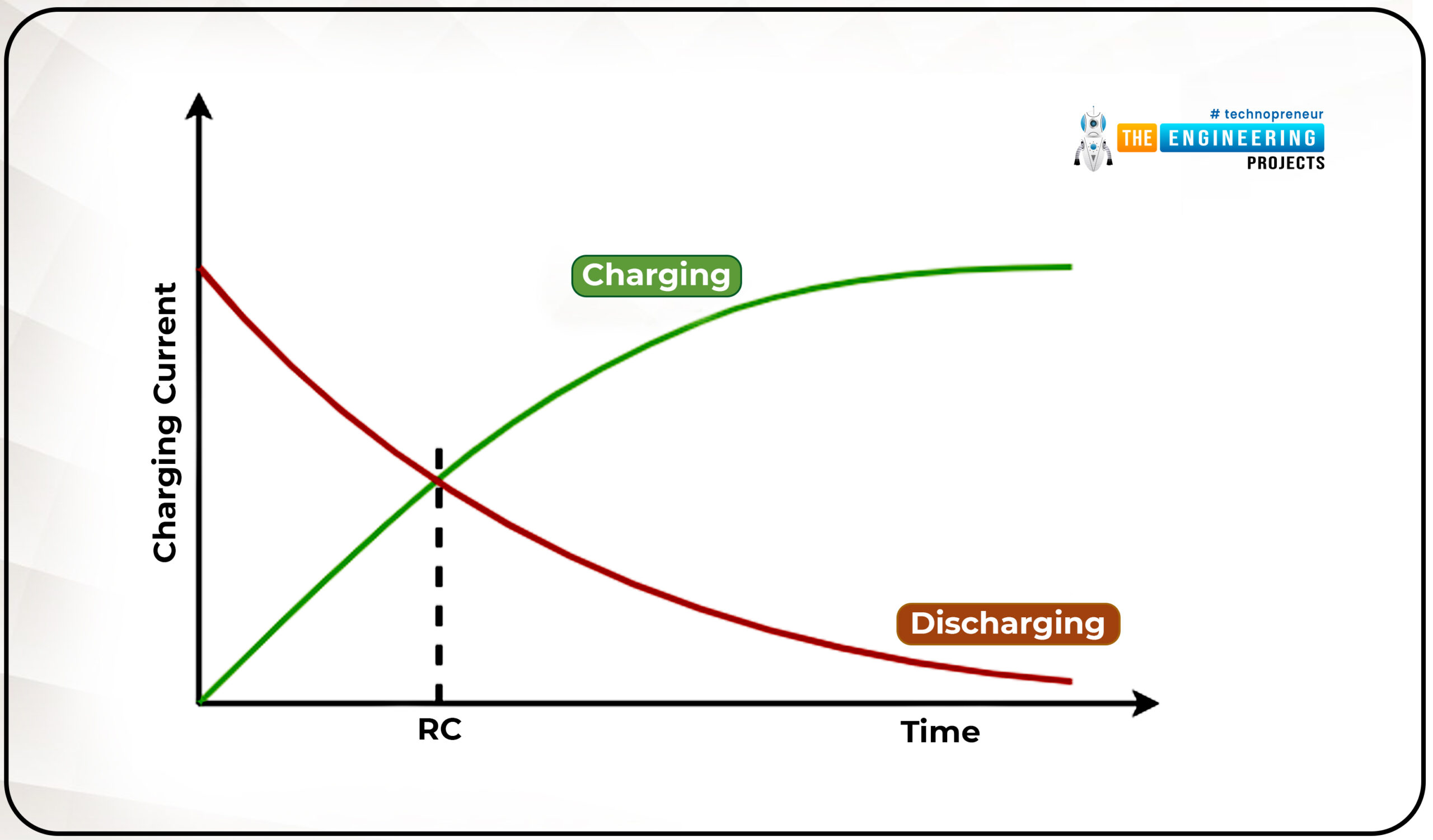
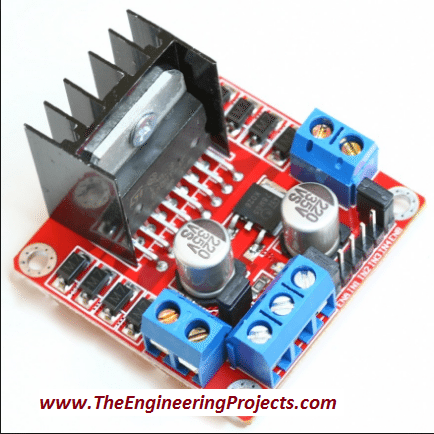
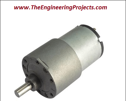