Tag: Simulink inverter model

2 articles found.

3 Level Cascaded H Bridge Inverter

Historical cascaded H-bridge inverter output plot, cascaded H bridge, MATLAB Simulink, inverter analysis

Hello friends! Today we will examine a cascaded H-bridge inverter in MATLAB and Simulink. We will begin with one bridge, work out its output states, and then see what changes when we connect bridge outputs in series and arrange three phases. The historical project is titled “3 Level Cascaded H Bridge Inverter.” We will retain that title, but distinguish a bridge's three possible output levels from the number of phases and the larger set of levels available from a cascade. Those are different properties of a converter. The original diagrams and scope images remain below so you can follow the model. They illustrate an older simulation environment. This revised explanation does not claim a fresh simulation run or treat a screenshot as proof of an inverter's efficiency or hardware readiness. F ...
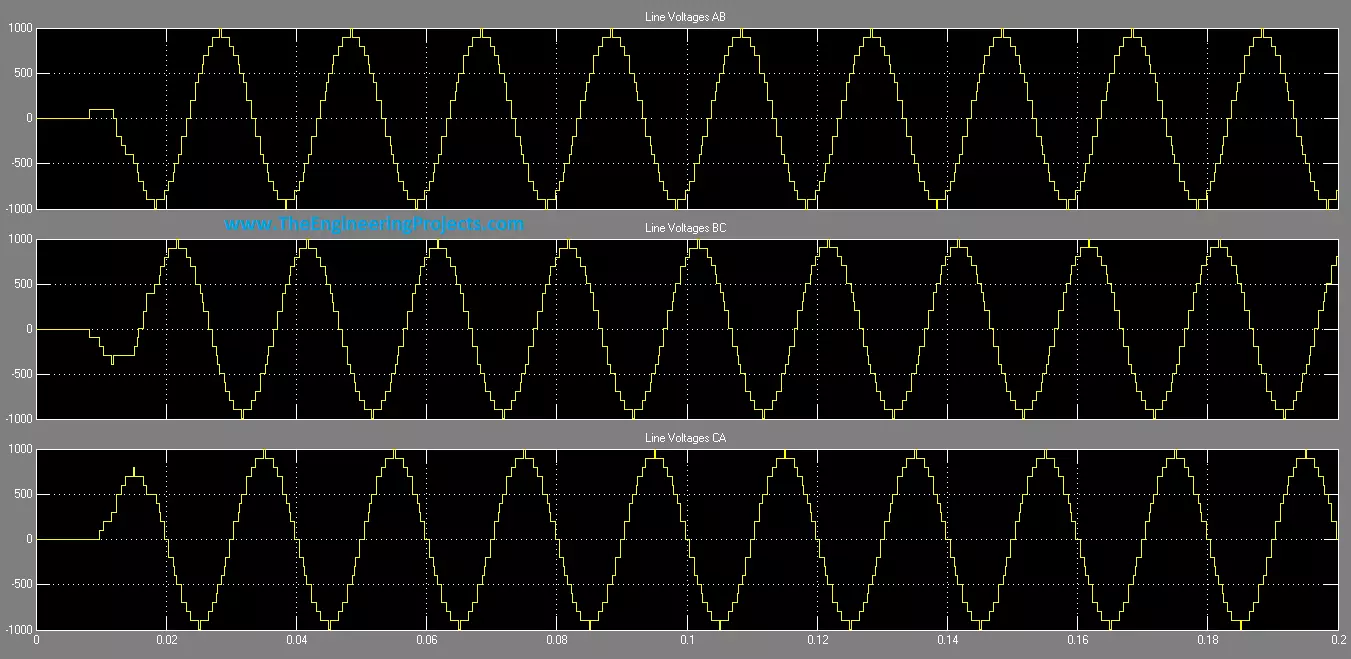
11 Level 3-phase Cascaded H Bridge Inverter

Eleven-level cascaded inverter waveform overview, cascaded H bridge, eleven level inverter, Simulink power model

Hello friends! Today, we will study an 11-level, three-phase cascaded H-bridge inverter in MATLAB and Simulink. We will begin with one H-bridge cell, connect five cells in series to form a phase, and then combine three phase assemblies. This approach makes the voltage levels easier to understand than starting with a large diagram full of switching signals. The original project illustrates the overall arrangement and retains useful phase and line-voltage plots. We will keep those images while correcting the distinction between gate signals and power sources, the switching requirements for eleven levels, and the meaning of the older switch-model parameters. These details determine whether a simulation represents the intended converter. Our emphasis is a transparent simulation model. We will ...