


What is Thevenin’s Theorem


What is Thevenin’s Theorem
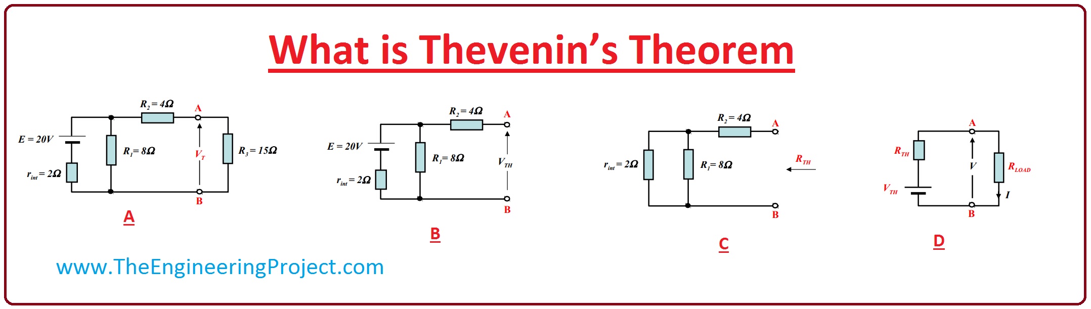
- Thevenin Theorem stated that the circuitry which has many resistors and voltage sources can be transformed into such circuitry which has one resistance and single source.
- To see how this rule works we solve a circuitry.
- In the given diagram, you can see that there is 20 volts voltage source and 15-ohm load resistance which is represented by R3.
- To apply Thevenin theorem to this circuit, first of all, we find VTH which is open circuit voltage for this we will eliminate the load resistor from the circuit. After removing R3 we get the resultant circuit which is represented by B in the diagram.
- Remove all voltage sources from the circuit and put their internal resistances value in the circuit.
- Then calculate the equivalent resistance which is also known as the Thevenin resistance, the resultant circuit is shown in the given diagram as C.
- After this make Thevenin equivalent circuitry which has source and Thevenin resistance then add load resistance to the circuitry to find the voltage across it. Thevenin equivalent circuit is denoted as D in a given diagram.
Why we use Thevenin Theorem?
- The most complex systems of circuits have some non-variable components and some have variable.
- The suitable example for this is our house wiring circuitry which is joined with the different loading devices like motors, fans or some lighting.
- If some time in special cases we want to find current and voltage values at every component of house wiring. It will take time and will be very difficult to find the electrical parameters of every element.
- To reduce these difficult calculations, a resultant circuitry of house wiring is created so that we can easily find the parameters and analysis of circuitry become easy.
- This equivalent circuitry which we make to reduce our calculation easy is called Thevenin equivalent circuitry.
Working of Thevenin’s Theorem
- To observe the practical implementation of Thevenin theorem, we will discuss its working by a given example.
- We create circuitry to calculate the value of current (I) moving in the circuitry.
- To implement Thevenin theorem we have to monitor these 3 steps.
- First of all, calculate the value of resister by eliminating EMF sources and load resistance.
- Then find the Thevenin voltage (V) after inserting the voltage (V) source in circuitry.
- Then already find resistance and voltage values which are Thevenin voltage and resistor use to find current passing through the load.
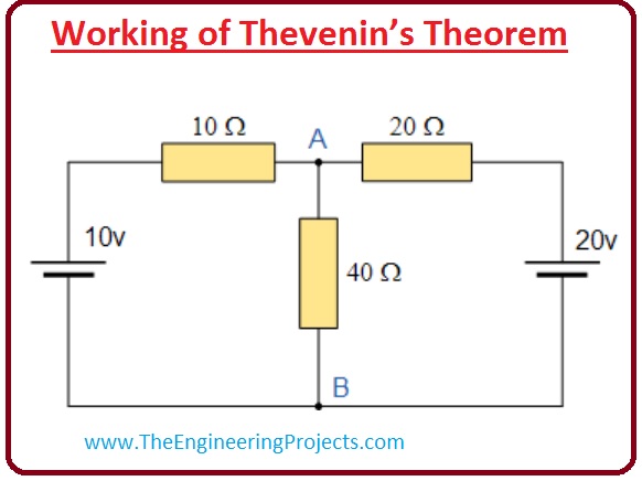
- Now we apply these steps practically on a circuit.

- In given circuit diagram we can see that forty-ohm resistance, which linked with the points A and D eliminate this resistance and all voltage sources in the circuit.
- After this, we will develop a circuitry which has only 2 resistances in the circuit.
- Now we calculate the value of Thevenin resistance (R), R1 and R2 are parallel to each other.
Rt = (R1 x R2)/(R1 + R2) = (20 x 10)/(20+10) = 6.67 ohm
Step 2:- In this step we will add, removed voltage sources to find the value of thevenin voltage.
- In the given diagram, we can use ohm law to find the value of the current flowing in this circuitry.
I= V/R = (20v-10v)/(20ohm + 10 ohm) = 0.33A
- Now we find the value of voltage.
VAB = 20 - (20 ohm x 0.33A) = 13.33 V
VAB = 10 + (10 ohm x 0.33A) = 13.33 V
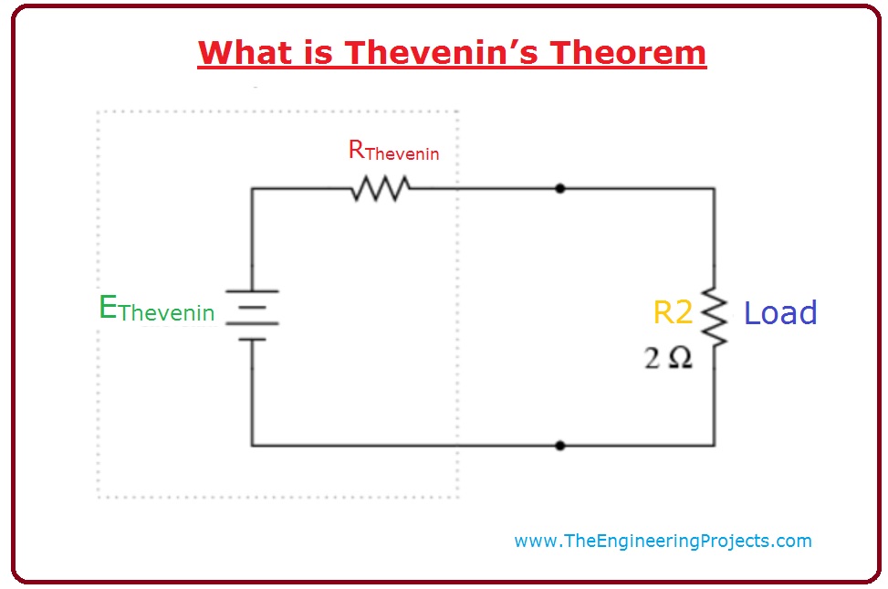
Step 3:- Now we have our Thevenin Resistance and Voltage we can put our Thevenin equivalent circuit together with our original load resistor as shown below.
- As we have found resistance and voltage values, now we find the value of current the circuit for the third step is shown in the given diagram.
- We use ohm’s law to measure the value of the current.
I= V/R = 13.33V/(6.67 +40) = 0.286A

Limitations of Thevenin Theorem
- These are some limitations of Thevenin Theorem, you must keep in mind while working on the different circuitries.
- This theorem is only appropriate for such circuitry which has linear elements like a resistor, capacitor, etc. It will not work for such circuitries which has the diodes, transistors these are not linear components.
- It also not work for the uni-lateral systems.
- It also not work for such circuit which has magnetic linking among the load and the circuitry which has to convert into the Thevenin circuitry.
Applications of Thevenin's Theorem
- These are some applications of Thevenin Theorem.
- This rule is applied to such circuitries in which load resistance varies, after some time it necessary to measure the value of resistance, Thevenin theorem is best for this circuitry to find the value of current and voltage.
×
![]()


