Hi Guys! Hope you’re well today. I welcome you on board. In this post, I’ll walk you through Electronics DIY Projects to Improve Work from Home.
Electronic devices are not cheap and rightly so. Since you require advanced setup and technical skills to build something sophisticated and delicate. The good news is that you don’t have to spend a fortune on such devices since DIY electronic projects are the solution. You can make similar electronic projects you find online at home and save a lot of money. Some people prefer working on a breadboard while others prefer building on printed circuit boards. However, if you’re new to this field, we’ll suggest you start from the breadboard, before building your projects on the PCBs. The good thing is that you don’t require a big setup or advanced tools to work on breadboards. Basic computer knowledge and a few tools and electronic components would suffice.
Know that nearly all of these electronics projects can be developed in less than a day if you have the required tools and components. It won't be difficult to test out these creative ideas for electronics projects because, fortunately, you can search hot electronics parts from kynix for a low price.
I suggest you read this article all the way through, as I’ll be covering in detail electronics DIY projects to improve work from home.
Let’s get started.
Electronics DIY Projects to Improve Work From Home
The long, warm months ahead can only mean one thing for DIY enthusiasts: polishing up the skills over the project after project. For some people, that can include finishing a picture or creating original dishes in the kitchen. And for tech nerds, it is learning new software or building electronic projects at home.
Looking for easy ways to spruce up your technical skills? These simple DIY Electronic Projects would help you to get your hands dirty in the electronic field without spending a lot of time and money.
1: Lead Acid Battery Charger
This is a simple electronic project used to charge your lead acid battery. It comes with LM 317 which is the main component of the circuit that serves as an operational amplifier mainly employed to deliver the exact charging voltage to the battery.

Components Used
Operational Amplifier LM 317
Transistor BC 548
Transistors
Capacitors
Potentiometer
How It Works
LM317 provides the correct voltage for the circuit and the transistor BC548 is employed to control the charging current delivered to the battery.
It is worth noting that one-tenth of the Ah value of the battery must be charged - the basic idea behind charging this circuit. The charging current can be adjusted using the potentiometer R5. While Q1, R1, R4, and R5 regulate the battery's charging current. The current flowing through R1 rises as the battery charges and it changes how Q1 conducts. The voltage at the LM 317's output rises because Q1's collector is connected to the IC LM 317's adjustment pin.
The charging current is reduced by the charger circuit after the battery is fully charged, and this mode is known as trickle charging.
2: FM Transmitter Circuit
Signal transmission is crucial when you want people to hear someone from a distance. Especially in factory and college settings to allow people to hear programs and speeches within range. This is a low-cost, simple electronic project used to create an FM transmitter circuit that has a 2-kilometer range for signal transmission.
Components Used
Matching Antenna
Transistors BC109, BC177, 2N2219
Capacitors
Resistors
Battery 9 to 24 V

How It Works
This is a simple DIY electronic project that you can easily develop at home. It comes with a 2 km range for transmitting the signals.
In this setup, a 9 to 24 DC power supply battery is used to power the circuit which not only ensures the optimum performance but also helps in reducing the noise.
The traditional high-sensitive preamplifier stage is formed with the transistors Q1 and Q2. Know that the audio signal required to be transmitted is connected to the base of Q1 using capacitor C2.
The oscillator, mixer, and final power amplifier functions are all carried out by transistor Q3. And the biasing resistors for the Q1 and Q2 preamplifier stage are R1, R3, R4, R6, R5, and R9. The tank circuit, which is formed by C9 and L1, is crucial for producing oscillations.
The FM signal is coupled to the antenna by inductor L2. Recognize that, the circuit frequency can be adjusted by varying C9 and R9 is employed to adjust the gain.
Make sure you apply this circuit on good-quality PCBs, as poor-quality connections can hurt the overall performance of the circuit.
3: 150 W Amplifier Circuit
Tired of your speaker’s low noise? Don’t panic! Since this is another easy-to-design electronic circuit that provides 150W to the four Ohm speakers – enough to provide you with a lasting, ruthless buzz to rock and roll. The basic component of the project is the pair of Darlington transistors TIP 142 and 147.
Components Used
Darlington transistors TIP 142 and 147
Transistor BC558
Resistors
Diode 1N4007
Electrolytic Capacitors rated at least 50V

How It Works
This circuit is effective for those just starting in the electronic field. In this circuit, TIP 147 and 142 are complementary Darlington pair transistors known for their durability that can handle 5 A current and 100V.
Know that Q5 and Q4 of two BC 558 transistors are joined together as a pre-amplifier also called a differential amplifier. This is used for two main reasons: for providing negative feedback and for reducing the noise at the input stage, thus improving the overall productivity of the amplifier.
While TIP41 (Q1, Q2, Q3) and TIP 142, TIP 147 together are employed to drive the speaker. This circuit's construction is so robust that it can be put together by soldering directly to the pins. A dual power supply with a +/-45V, 5A output can power the circuit.
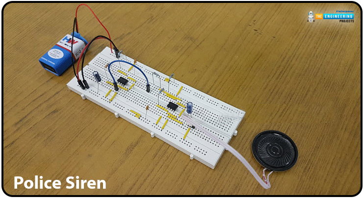
4: Police Siren
A siren is a device that produces a usual louder sound to alert and/or attract people or vehicles. Typically, ambulances, police cars, fire trucks, and VIP cars are among the vehicles that use the siren.

Basic Component
The basic component of the project is the 555 timer which is one of the most adaptable chips that can be applied in practically all applications because of its multi-functionality. It is an 8-pin chip with a 200 mA direct current drive output that comes in a DIP or SOP packaging. This IC is a mixed-signal semiconductor since it has both analog and digital components. The IC's primary uses include producing time, clock waveforms, square wave oscillators, and numerous more functions.
Working Principle
Using two 555 timers, speakers, and a basic circuit, this breadboard project creates a police siren sound. As indicated in the diagram above, an 8 Ohm speaker is connected to two 555 timers.
Note that, one 555 timer is attached in an astable mode (it carries no stable state, instead comes with two quasi-stable states which quickly change from one state to another and then back to the original state) and the second 555 timer is connected in the monostable mode (one of the two states is stable, and the other is nearly stable.
When a trigger input is applied, it changes from a stable state to a quasi-state and then returns to the stable state on its own after a certain amount of time) to achieve the appropriate frequency.
This setting creates a siren with a frequency of about 1 kHz. Using the knob in the circuit, the siren sound frequency can be changed to match the police siren sound. The siren is used not just in automobiles but also in many businesses, mills, and other establishments to notify workers of their shift times.
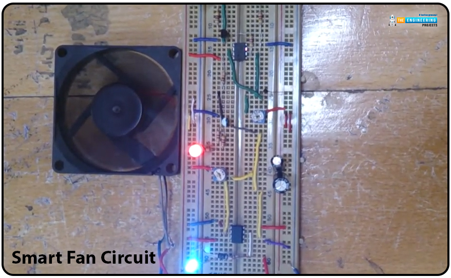
5: Smart Fan Circuit
With the help of a few basic components, a cooling system to regulate a DC fan is designed in this simple breadboard project. The goal of this project is to build a cooling system by easily operating a DC fan without the need for microcontrollers or Arduino, but rather by using readily available and straightforward electronic components. Once the temperature hits a certain level, this fan will turn on.

Basic Components
5V DC Fan
5V battery
NTC thermistor-1 kilo-ohm
LM555 Timer
NTC thermistor-1 kilo-ohm
BC337 NPN Transistor
diode 1N4007
capacitors 0.1 uF & 200 uF
LEDs
Connecting Wires
Resistors like 10k ohm, 4.7k ohm, 5k ohm
Breadboard
Working Principle
In this circuit, the DC fan can be controlled using a thermistor. The resistance of the thermistor, a particular type of resistor, is largely dependent on temperature. Thermistors come in two main types including NTC (Negative Temperature Coefficient) and PTC (Positive Temperature Coefficient).
When an NTC is employed, the resistance decreases as the temperature rises. This is the opposite in the case of PTC where resistance and temperature are directly proportional to each other.
When the temperature reaches a certain threshold, the fan turns on. The first LED, "The green LED," which indicates rising temperature, will turn ON as the temperature rises.
The second LED will turn ON when the temperature reaches the second threshold, and the fan will run as long as the temperature is over the second threshold. The fan will continue to run for a set amount of time once the temperature returns to an acceptable level.
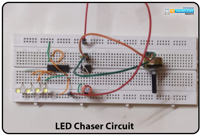
6: LED Chaser Circuit
This simple LED chaser circuit is developed using a 555 timer and 4017 IC. Together, the two ICs in this project run the LEDs in a sequence to create the illusion that they are chasing each other.

Basic Components
555 timers
CD 4017 IC
Resistors 470R, 1K & 47K
1uF capacitor
Connecting Wires
5 to 15 V power supply
Breadboard
Working Principle
Before you start working on the project, you must visit the pin diagrams of both ICs. It will help you to identify the correct pins to be used in the project.
When an IC – a 555 timer – is used in an astable mode (that produces a square wave), its output fluctuates continually between high and low supply voltages. For instance, an LED will continuously blink if it is connected between 555 timers and the ground.
The CLK input of a decade counter is connected to the output of a 555-timer IC. This IC has ten output pins, each of which is wired to an LED. The remaining output pins will all be switched OFF once the first pin is turned ON.
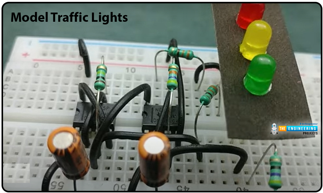
7: Model Traffic Lights
This simple, low-cost traffic lights model circuit is designed using two 555 timers and some other basic components.
This circuit comprises three LEDs for the indication of RED, Yellow, and Green traffic light signals. First, it will turn ON a green LED, maintains it on for a while, then briefly turns ON a yellow LED before turning on a red LED that remains ON for almost the same amount of time as the green LED.

Basic Components
555 Timers
Resistors of 100K, 47K, 2 x 330R, 180R
LEDs – Yellow, Red, and Green
Connecting Wires
Power Supply 5-12 V
2 Capacitors of 100uF
Breadboard
Working Principle
The circuit comes with two astable circuits where the first astable circuit will power the other. Therefore, only if the first 555 timer IC's output is ON will the second 555 timer IC be powered.
When the output of the first timer remains at 0V, it will turn ON the red LED. The green LED turns ON anytime the output of the second 555 timer IC is at a positive voltage, and the yellow LED will turn ON when the second 555 IC is in discharge mode.
The yellow and green LEDs would turn on at the same time. However, even before the voltage across the capacitor of the first 555 timer IC reaches two-thirds of the supply voltage, the output of the first 555 IC goes off, which will allow the red LED to turn ON and the yellow LED to turn OFF.
Conclusion
Hope you’ve got a brief idea of how to get started with electronic projects.
Getting hands-on experience will not only improve your technical skills but also help you to develop critical thinking to get familiar with advanced electronics.
It’s okay to become acquainted with PCBs, but if you don’t know how to solder properly or how to design a good PCB layout, it’s preferred to start working on the breadboard to keep your project up and running.
That’s all for today. Hope you’ve enjoyed reading this article. If you’re unsure or have any questions, you are welcome to reach out in the section below. I’d love to help you the best way I can. Thank you for reading this post.


 Tutorials
 syedzainnasir
 0 Comments


 2.3k
2.3k
 953
953
 921
921
 2.1K
2.1K

