Hello friends, I hope you all are doing great. Today, I am going to share the M5Stack AtomS3 Library for Proteus. The AtomS3 is one of the smallest complete computers you can buy: a dark cube only 24 mm on a side, with an ESP32-S3, Wi-Fi, a tiny 0.85 inch colour display and a key tucked under the screen. You press the whole screen to click it, which feels surprisingly good. With this library it runs your ESP32 Arduino sketch in Proteus 8.5, with the display and the key working on the part.
M5Stack AtomS3 Library for Proteus
Latest version: V1.0 (November 2026, this tutorial)
Other ESP32 boards and modules: ESP32 DevKit V1 · ESP32-DevKitC V4 · ESP32-S3 DevKitC-1 · ESP32-C3 SuperMini · ESP32-C6 DevKitC-1 · TTGO T-Display · T-Display S3 · XIAO ESP32-C3 · XIAO ESP32-S3 · ESP32 Feather V2 · QT Py ESP32-S3 · ESP32-C5 DevKitC-1 · Olimex ESP32-POE · FireBeetle 2 ESP32-E · T-Call SIM800L · T-SIM7600 · T-Beam Supreme · M5StickC PLUS2 · ESP32-2432S028 CYD · M5Stack Core2 · LilyGO T-Deck · LOLIN S2 Mini · Heltec WiFi LoRa 32 V3 · LilyGO T-Beam · ESP32-CAM · ESP32-WROOM-32 · AirLift WiFi Shield · AirLift ESP32 Breakout · WT32-ETH01
Other displays: OLED · Nokia 5110 · LCD 128x64 · ST7735 · ST7789 · ILI9341 · TFT Shield 2.4 inch · TFT Shield 3.5 inch · E-Paper
Temperature and weather sensors: DHT11 / DHT22 · DS18B20 · BME280 · BMP280 · SHT31 · AHT20 · BME680 · MLX90614 · MAX6675
Helping Tools
- Laptop WiFi Monitor: a laptop on the Wi-Fi of your design: a browser, a TCP / UDP terminal and ping
- Mobile WiFi Monitor: a smartphone that opens the pages of your board and sends it commands
- Serial Monitor Advance: a serial terminal window for the UART of your board
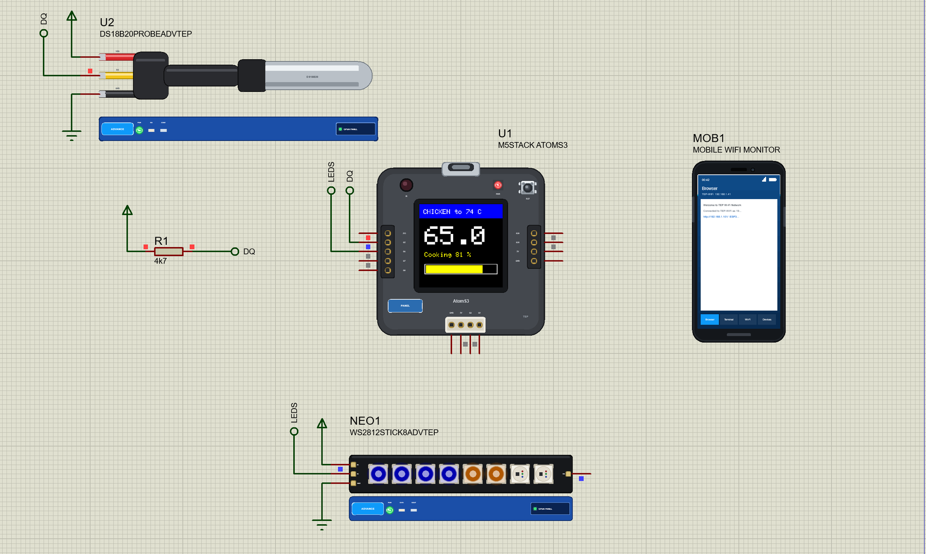
For the demo we built a Wi-Fi cooking thermometer, the small kitchen helper that stops you from cutting into a roast to check it. A DS18B20 probe goes into the food, the screen shows the temperature, and a press on the screen picks what you are cooking. A WS2812 LED stick fills up as the food heats, and a phone on the same Wi-Fi shows the same numbers from the next room.
NOTICE: Proteus has no ESP32-S3 model, so our team has put a lot of effort into building this board ourselves: the AtomS3's pins, key, display and Wi-Fi are all our own model, and your sketch compiles with our free TEP Boards for Proteus add-on. Your feedback is the fuel that keeps us going, so please tell us what you think in the comments below or in the M5Stack AtomS3 board of our forum. And if our free libraries help you, you can buy us a coffee. So, let's get started with the M5Stack AtomS3 Library for Proteus:
What is the M5Stack AtomS3?
The AtomS3 is M5Stack's pocket development kit. Inside the small case is an ESP32-S3FN8, with two 240 MHz cores, Wi-Fi and 8 MB of flash on the chip. The top is a 128 x 128 IPS screen driven by a GC9107, and under that screen sits a programmable key. The case also holds an MPU6886 motion sensor and an IR emitter. One side has USB-C and a reset key, and there is a 4-pin Grove socket with six more GPIO pins on the back, so a sensor can be added without soldering.
| AtomS3 | M5StickC PLUS2 | ESP32 DevKit | |
|---|---|---|---|
| Size | 24 x 24 x 13 mm | 54 x 25 x 16 mm | about 55 x 28 mm |
| Display | 0.85 inch, 128 x 128 | 1.14 inch, 135 x 240 | none |
| Keys | the screen, and reset | three | BOOT, EN |
| Connect sensors by | Grove and six pins | Grove and HAT | pin headers |
| Best for | tiny finished gadgets | wearables | prototypes |
A Screen That Is Also a Key
Most small boards have a row of tiny buttons at the edge. The AtomS3 mounts its screen on a switch, so the whole front of the cube is one big key. That sounds like a small trick, but it changes how a project feels. A tiny display and one key are enough for many gadgets: press to change the page, press to pick a setting, press to stop an alarm. Our demo uses exactly that, and if you know our M5StickC PLUS2 Library for Proteus, you will find the same kind of sketch here on an even smaller part.
Features of the M5Stack AtomS3 Library for Proteus
- The cube as it looks: the dark case, the square screen in its black frame, USB-C, the reset key, the IR window, the Grove socket and the pins of the back, with our small TEP signature.
- Your sketch: a .hex for "M5Stack AtomS3 (TEP Proteus)" with the real GPIO numbers - analogRead 0 to 4095, analogWrite and ledc PWM, attachInterrupt, tone, Serial, Wire and SPI.
- The display on the part: the GC9107 with Adafruit's graphics library, 128 x 128 pixels in full colour.
- A key under the screen: click the screen with the mouse, and GPIO41 goes LOW.
- Wi-Fi: WebServer and HTTPClient in station mode, with our phone and laptop windows on the same network.
- A complete package: about 4.1 MB with the part, the add-on, the DS18B20, WS2812 and Wi-Fi monitor libraries and the demo, without the source code of the models.
The M5Stack AtomS3 in Proteus
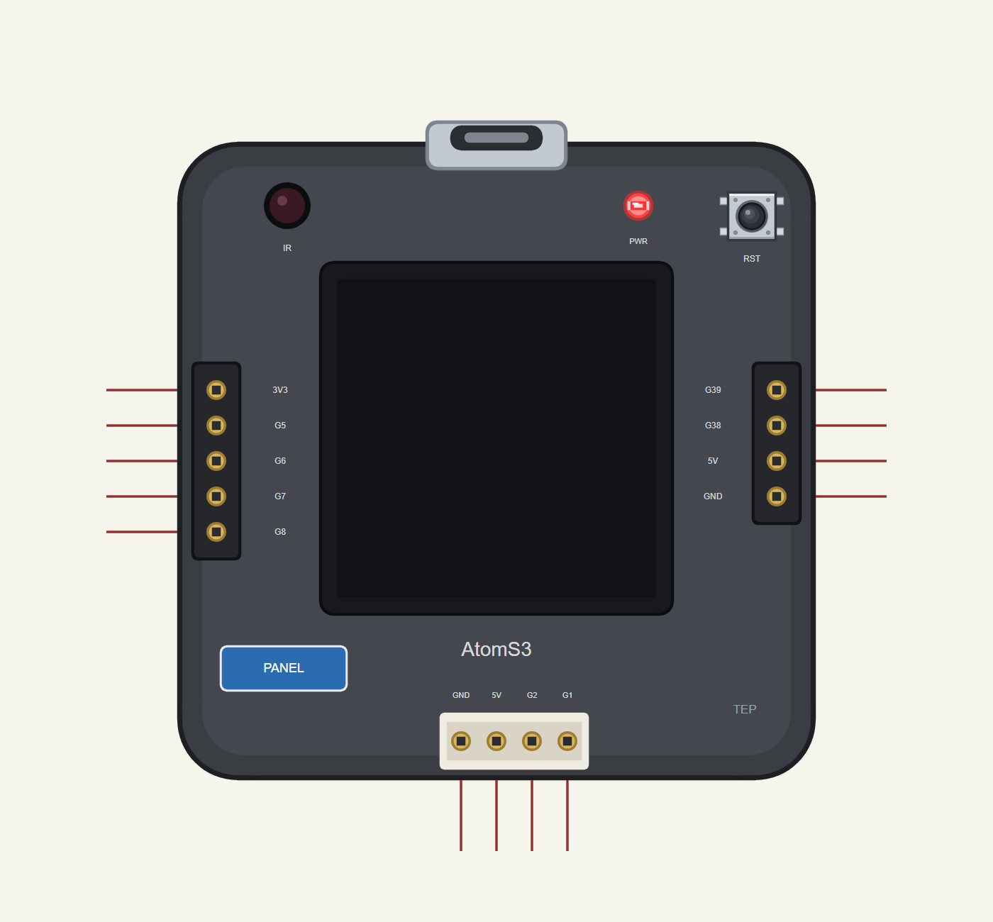
Search ATOMS3 in Pick Devices; the device is in TEPATOMS3.LIB (Microprocessor ICs, ESP32 Boards), with the prefix U. It has two windows: click the USB-C port for the serial monitor, and the blue PANEL pad for the panel. A click on the screen does not open anything, because the screen is the key. On the real product the six pins are on the back of the case; we drew them at the sides, so that you can wire them. We also drew the cube larger than life, so that you can read the display on the sheet.
The Pins
| Place | Pins | What the library does with them |
|---|---|---|
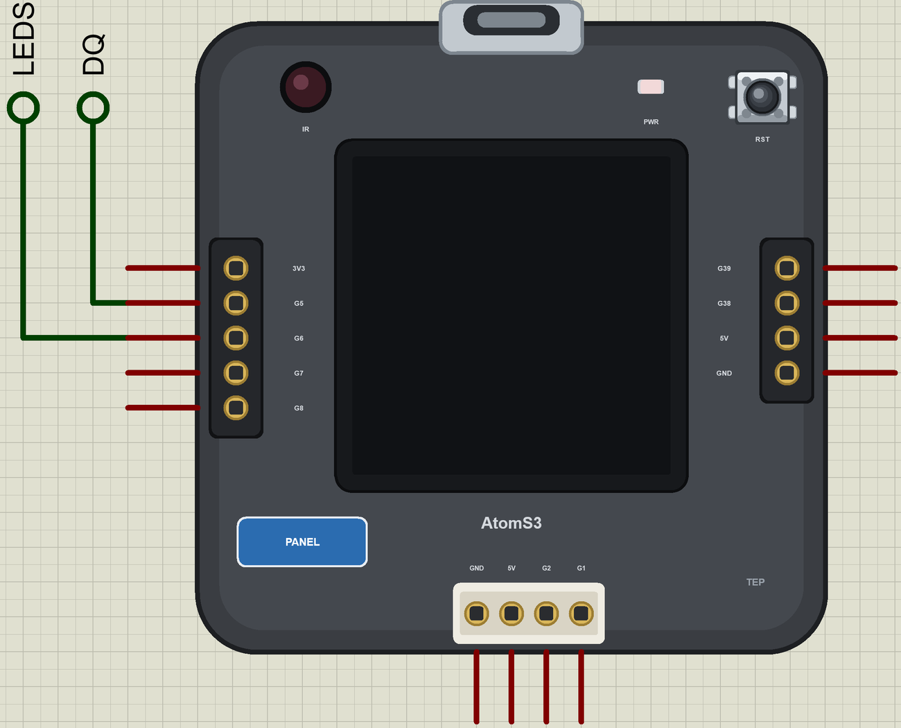
| Left row | G5, G6, G7, G8 | GPIO, PWM, interrupt, analogRead |
| Right row | G38, G39 | GPIO, PWM, interrupt |
| Grove | G2, G1 | Wire SDA and SCL, or GPIO |
| Sides | 3V3, 5V, GND | the supply |
| Inside | 21, 17, 15, 33, 34, 16 | the display and its backlight |
| Inside | 41, 4 | the key, LOW when pressed, and the IR emitter |
The variant gives the inside pins names, such as BUTTON_A, IR_PIN and TFT_CS, so a sketch reads clearly. The order of the two rows follows M5Stack's Atom range. The MPU6886 and IR light are not modelled. Note that M5Stack's own M5Unified and M5GFX libraries are not for this part: use the pins directly, as our demo does.
Download M5Stack AtomS3 Library for Proteus
Click the button below to download M5Stack-AtomS3-Library-for-Proteus-v1.0.zip (about 4.1 MB, without the source code of the models):
M5Stack AtomS3 Library for Proteus V1.0- README.txt: installation, the demo, the pins, the properties, troubleshooting and the limits.
- Proteus Library Files:
TEPATOMS3.LIBand the demo's parts:TEPDS18B20.LIB,TEPWS2812.LIB,TEPMOBILE.LIBandTEPLAPTOP.LIB. - Proteus Model Files:
TEPNET.DLL,TEPDS18B20.DLLandTEPWS2812.DLL. - Arduino Code: the demo sketch and the TEP Boards for Proteus add-on 1.51.0.
- Proteus Simulation: the demo project, its HEX file and copies of the DLLs.
No Proteus yet? Read How to Download and Install Proteus 7 and 8. New to libraries? Follow How to Install a New Library in Proteus.
How to Install M5Stack AtomS3 Library for Proteus
- Close Proteus and extract the whole zip file, for example to your Desktop.
- Copy the files from Proteus Library Files into the LIBRARY folder of Proteus.
- Copy the DLLs from Proteus Model Files into the MODELS folder, replacing an older TEPNET.DLL.
- Delete
TEPATOMS3.IDXfrom the LIBRARY folder if it is there. - For your own sketches, copy Arduino Code\TEP Boards for Proteus\hardware into your Arduino sketchbook (Documents\Arduino) and restart the Arduino IDE; the board is M5Stack AtomS3 (TEP Proteus). Install Adafruit ST7735 and ST7789, Adafruit GFX, Adafruit BusIO, OneWire, DallasTemperature and Adafruit NeoPixel from the Library Manager.
- Start Proteus, press P and search for ATOMS3.
Demo: a Wi-Fi Cooking Thermometer
Good cooks do not guess. Chicken is safe at 74 C, a rare steak is ready near 57 C, and bread is done at about 93 C in the middle. The only honest way to know is to measure inside the food, and opening the oven every few minutes loses heat and time. A thermometer that shows the number across the kitchen, and on your phone, does the watching for you.
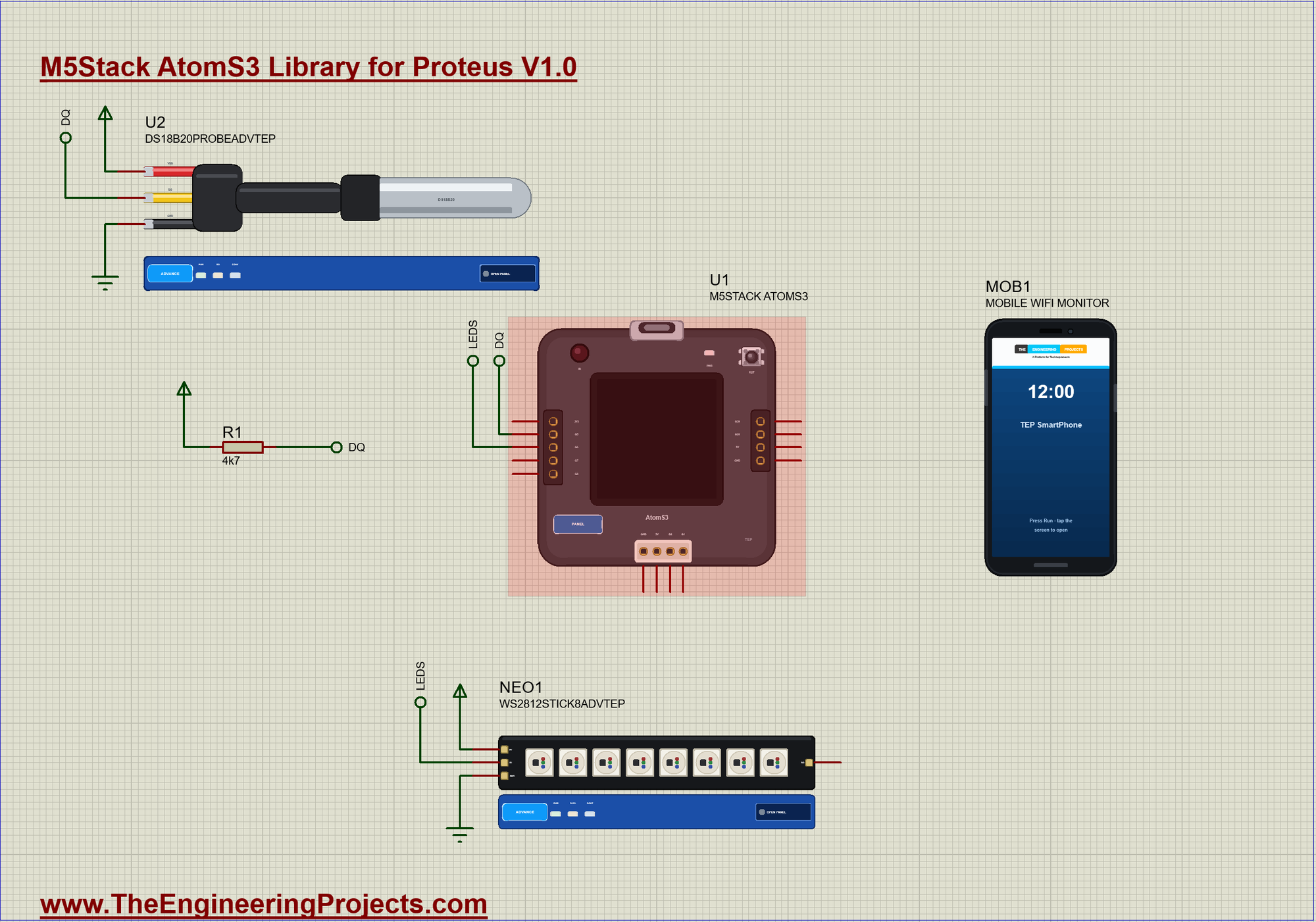
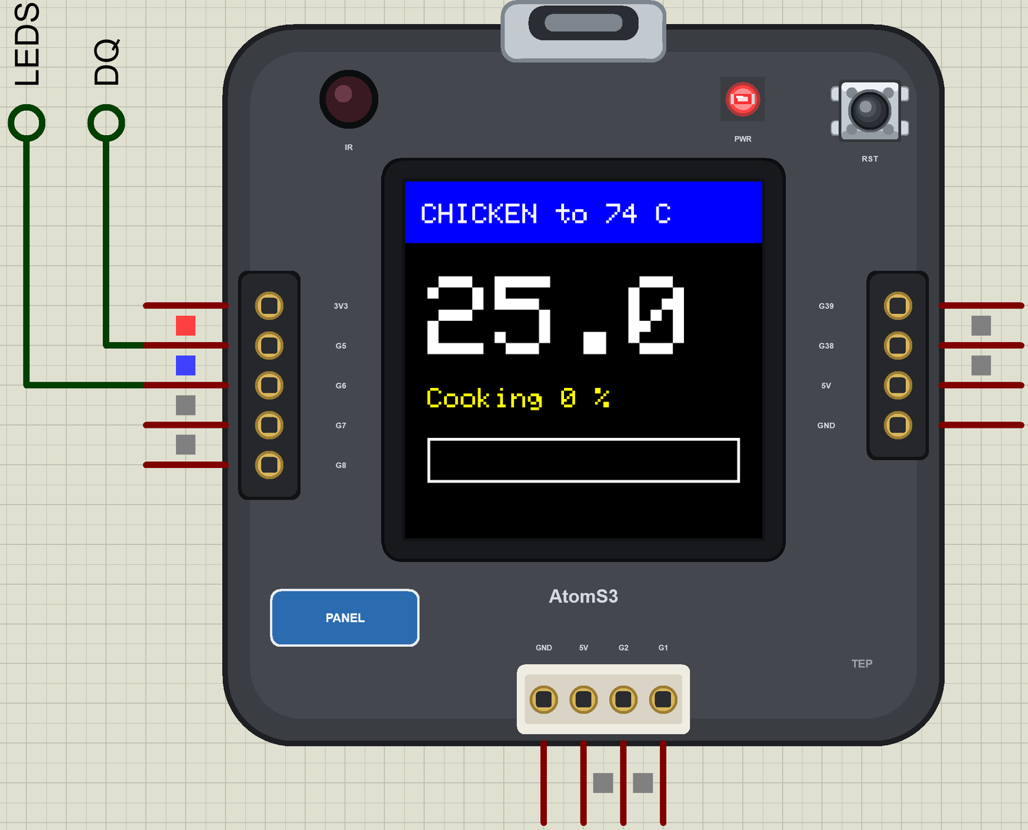
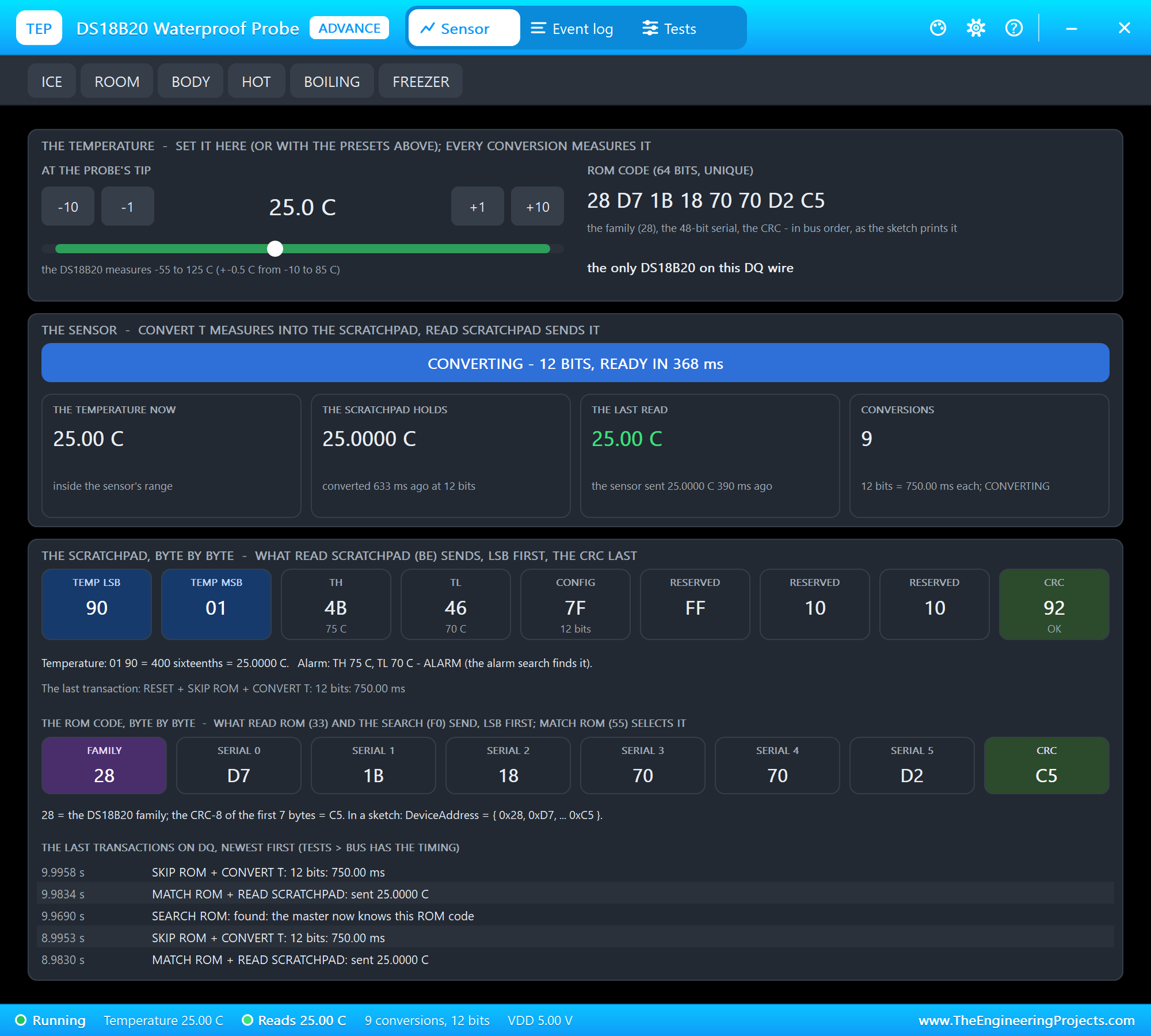
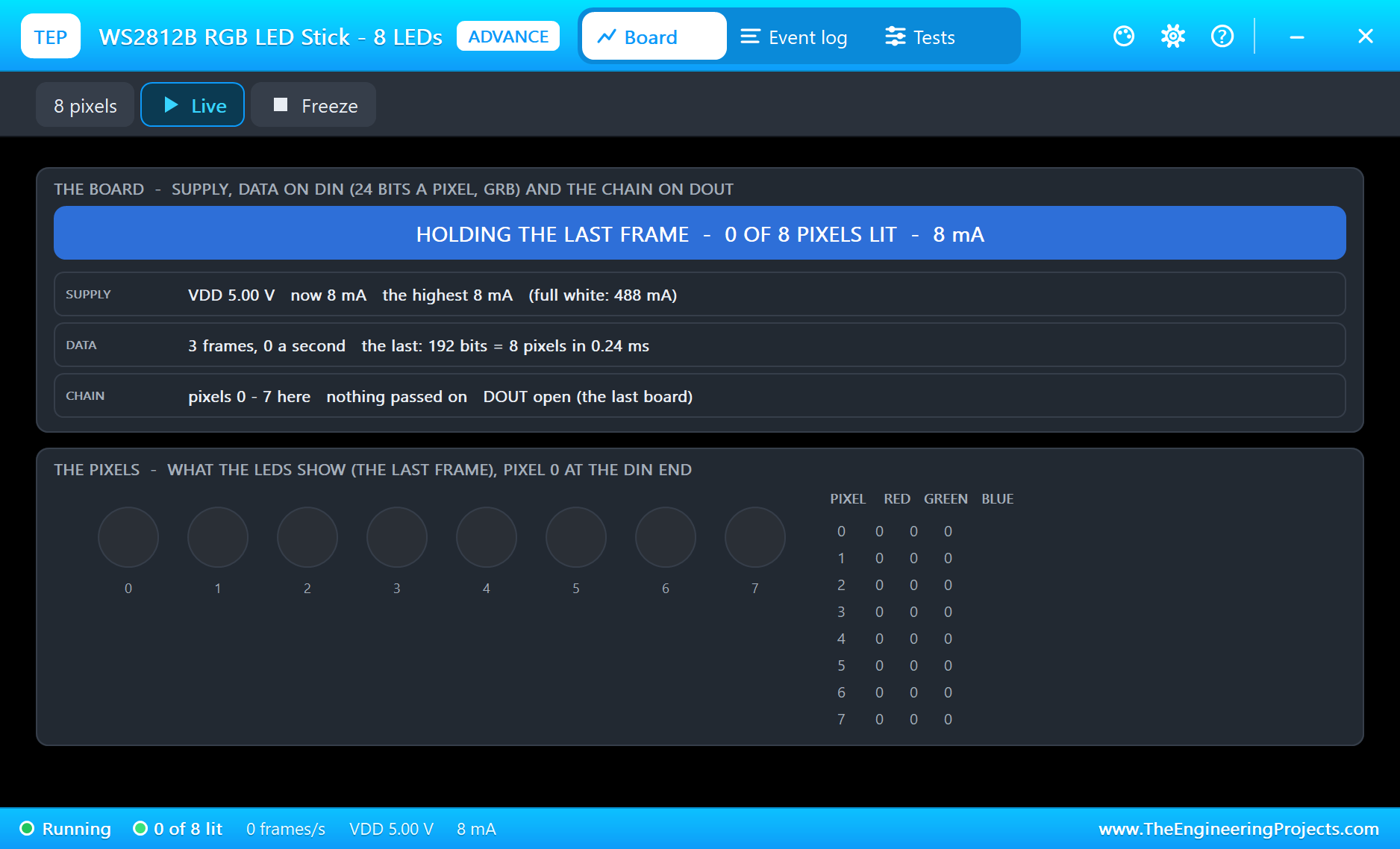
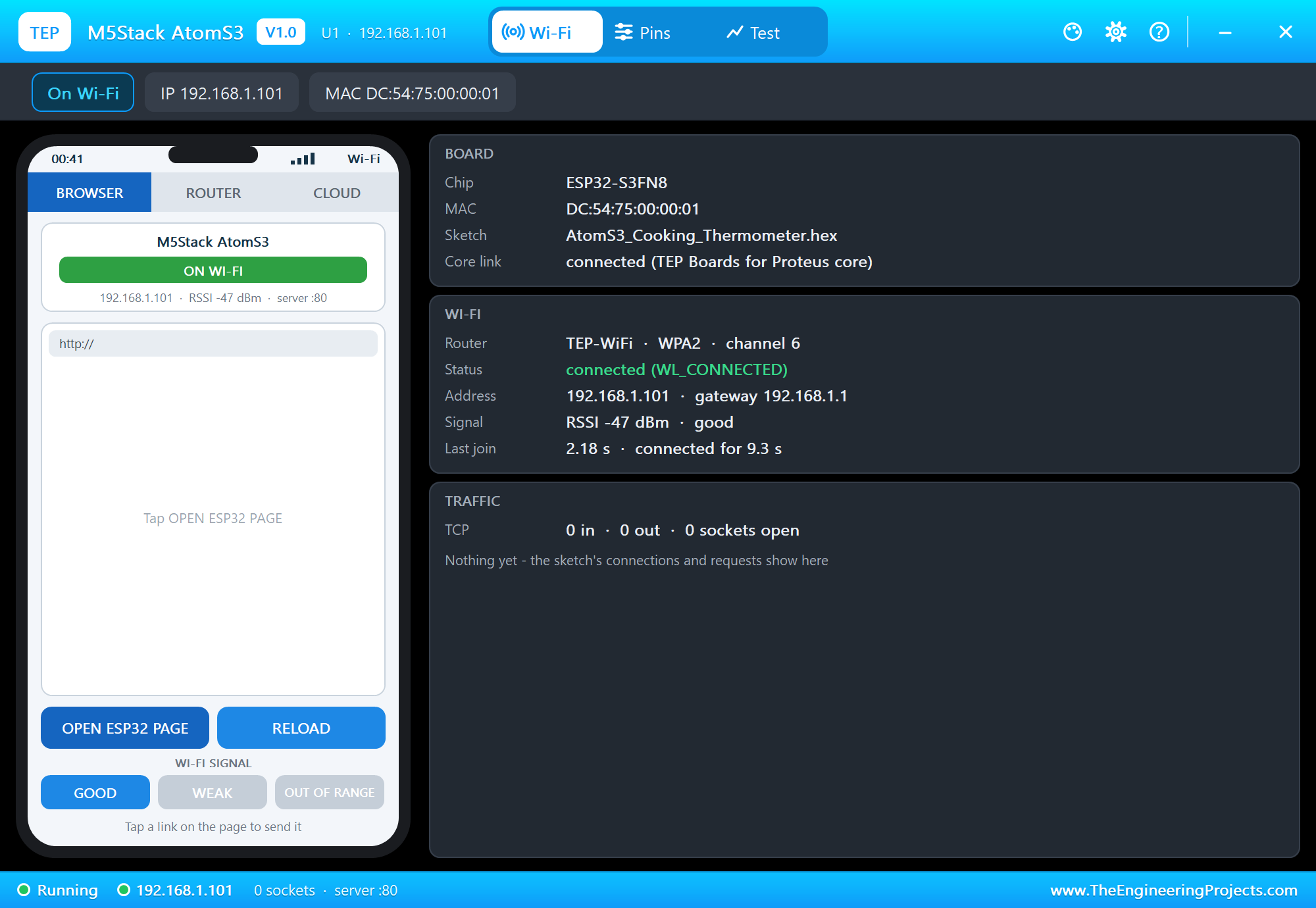
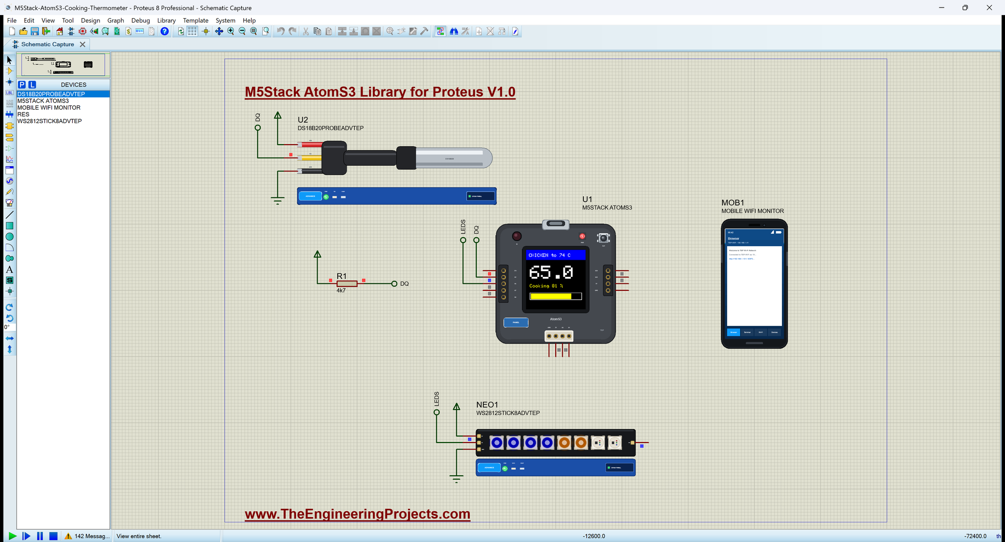
Open M5Stack-AtomS3-Cooking-Thermometer.pdsprj. U1 runs AtomS3_Cooking_Thermometer.hex. U2 is the waterproof probe from our DS18B20 Library for Proteus and NEO1 is the stick of eight LEDs from our WS2812B NeoPixel Library for Proteus, both in the Advance version. R1 is the pull-up that the 1-Wire bus needs. MOB1 is our Mobile WiFi Monitor, and the monitor is the same window as our TEP Serial Monitor Advance for Proteus.
| Module pin | Net label | AtomS3 pin | What it does |
|---|---|---|---|
| Probe DQ | DQ | G5 | the 1-Wire data line |
| R1 | DQ, VCC | - | the 4.7 kohm pull-up |
| Stick DIN | LEDS | G6 | the colours of the eight LEDs |
| VDD, 5V, GND | VCC, GND | - | the supply |
Why a DS18B20?
The DS18B20 is a digital thermometer in a tiny package, and the waterproof version sits in a steel tube on a long cable, which is just what a kitchen needs. It reports the temperature as a number, so a long wire adds no error. It measures from -55 to 125 C, with an accuracy of 0.5 C over the range that matters for cooking. A real food probe needs a food-safe tube and a cable rated for the oven, so check that before you use one near a roast.
How the 1-Wire Bus Works
The probe has only one signal wire, called DQ. Both sides can pull it LOW, and nobody ever drives it HIGH; that is the job of the 4.7 kohm pull-up resistor. Without R1, the line would float and every reading would fail. Each bit is a timed LOW pulse: the sketch pulls the line down for a short moment to send a 1, and for a long moment to send a 0. To read, it makes a short pulse and then looks at whether the probe is still holding the line. The OneWire library does all of this for us.
Driving the GC9107 Display
Adafruit has no library named for the GC9107, but we do not need one. This controller takes the same commands as the ST7789 for the things that matter: set a window, then send the pixels. So a very short class on Adafruit_ST77xx is enough. It holds the size of the screen and the list of start-up commands: wake up, use 16 bits for each pixel, turn on the colour inversion that this type of IPS glass needs, and switch the display on. Everything else, from text to rectangles, comes from Adafruit GFX:
class GC9107 : public Adafruit_ST77xx {                     // only the start-up differs from an ST7789
 public:
  GC9107() : Adafruit_ST77xx(128, 128, TFT_CS, TFT_DC, TFT_RST) {}
  void init() {
    static const uint8_t PROGMEM startUp[] = {
      5,
      ST77XX_SLPOUT, ST_CMD_DELAY, 120,
      ST77XX_COLMOD, 1, 0x55,                               // 16 bits a pixel
      ST77XX_INVON, 0,
      ST77XX_NORON, 0,
      ST77XX_DISPON, ST_CMD_DELAY, 20
    };
    commonInit(startUp);
    setRotation(0);
  }
};
Measuring Without Waiting
A DS18B20 takes 750 ms to make a 12-bit reading. If the sketch simply waited, the phone would wait too, and a press on the screen could be missed. So we call setWaitForConversion(false) in setup(). Once a second the sketch collects the last result and starts the next conversion in the same breath, and loop() stays free for everything else. It also ignores a reading of -127 C, which is the library's way of saying that the probe did not answer:
void readProbe() {
  if (millis() < nextRead) return;
  nextRead = millis() + 1000;
  const float t = probe.getTempCByIndex(0);
  probe.requestTemperatures();
  if (t < -100) return;                                     // no answer yet, or no probe
  const bool changed = fabs(t - temp) >= 0.05;
  temp = t;
  if (startTemp == 0) startTemp = temp;
  const float target = FOODS[food].target;
  setState(temp >= target + OVER_BY ? TOO_HOT : temp >= target ? READY : COOKING);
  if (changed) { drawTemp(); drawStick(); }
}
How Far Has It Come?
The progress is simple arithmetic: how far the temperature has come from the start, as a share of the distance to the target. If the food started at 25 C and the target is 74 C, then 65 C means 81 %. The constrain() keeps the answer between 0 and 100 %, and the first test stops a division by zero when the food is already past the target:
byte progress() {                                           // 0 .. 100 % of the way from the start to the target
  const float span = FOODS[food].target - startTemp;
  if (span <= 0) return 100;
  return constrain((temp - startTemp) * 100.0 / span, 0, 100);
}
The LED Stick
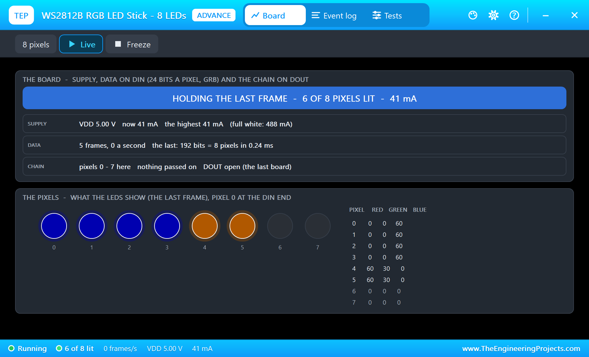
A WS2812 LED has its own small chip, and eight of them share one data wire. The sketch sends 24 bits for each LED, and each one keeps the first 24 bits it sees and passes the rest along. Adafruit_NeoPixel handles that tight timing; we just set the colours and call show(). Our stick works as a bar graph that you can read from across the room. The first four LEDs are blue, the rest are amber, all eight turn green when the food is ready, and all eight turn red when it is too hot:
void drawStick() {
  const byte lit = state == COOKING ? progress() * STICK_LEDS / 100 : STICK_LEDS;
  for (byte i = 0; i < STICK_LEDS; i++) {
    uint32_t colour = 0;
    if (i < lit) {
      if (state == TOO_HOT) colour = stick.Color(60, 0, 0);
      else if (state == READY) colour = (blinkOn || !alertOn) ? stick.Color(0, 60, 0) : 0;
      else colour = i < STICK_LEDS / 2 ? stick.Color(0, 0, 60) : stick.Color(60, 30, 0);
    }
    stick.setPixelColor(i, colour);
  }
  stick.show();
}
One Key, Two Jobs
The key under the screen has two meanings, and the sketch picks one by looking at what is happening. During an alert a press stops the blinking. The rest of the time a press moves on to the next food. Notice how it looks for the moment of the press, by comparing with the last reading, and ignores anything within 200 ms, because a real key bounces:
void readKey() {
  const bool down = digitalRead(BUTTON_A) == LOW;
  if (down && !keyWas && millis() - keyAt > 200) {          // a press, not a bounce
    keyAt = millis();
    if (alertOn) stopAlert(F("screen"));
    else chooseFood();
  }
  keyWas = down;
}
Starting Up
The display has its own SPI bus, on G17 and G21, and it is the only thing on it, so no MISO pin is needed. The backlight is a plain pin, so a real sketch can dim it. stick.show() right after begin() turns all the LEDs off. The sketch reads the first temperature as soon as it arrives, and that becomes the starting point for the progress bar:
void setup() {
  Serial.begin(115200);
  Serial.println(F("AtomS3 Cooking Thermometer - The Engineering Projects"));
  pinMode(BUTTON_A, INPUT_PULLUP);
  pinMode(TFT_BL, OUTPUT); digitalWrite(TFT_BL, HIGH);
  SPI.begin(TFT_SCLK, -1, TFT_MOSI, TFT_CS);
  tft.init();
  tft.fillScreen(ST77XX_BLACK);
  stick.begin();
  stick.show();
  probe.begin();
  probe.setWaitForConversion(false);
  probe.requestTemperatures();
  WiFi.begin(WIFI_NAME, WIFI_PASS);
  while (WiFi.status() != WL_CONNECTED) delay(100);
  Serial.print(F("Wi-Fi: http://")); Serial.print(WiFi.localIP()); Serial.println(F("/"));
  server.on("/", handleRoot);
  server.on("/next", handleNext);
  server.on("/stop", handleStop);
  server.begin();
  redraw();
  Serial.print(F(">> Food: ")); Serial.print(FOODS[food].name); Serial.print(F(", target ")); Serial.print(FOODS[food].target, 0); Serial.println(F(" C"));
}
The Page for the Phone
WebServer calls a function for each address, and that function builds the page as a String. The links /next and /stop call the same functions as the key, so the screen and the phone always agree. Any browser on the same Wi-Fi can use the page, and no app is needed:
void handleRoot() {
  String h = F("<html><body><h2>Cooking Thermometer</h2><p>");
  h += FOODS[food].name;
  h += F(": ");
  h += String(temp, 1);
  h += F(" C of ");
  h += String(FOODS[food].target, 0);
  h += F(" C</p><p>");
  h += state == TOO_HOT ? F("TOO HOT") : state == READY ? F("READY") : F("COOKING");
  h += F("</p><p><a href='/next'>NEXT FOOD</a></p><p><a href='/stop'>STOP ALERT</a></p></body></html>");
  server.send(200, "text/html", h);
}
Keeping the Loop Quick
Five small jobs share loop(): the web server, the key, the probe, the blinking and the log. Each one checks its own clock with millis() and returns at once when it has nothing to do. The sketch also redraws the screen only when a number has changed. On this small screen that takes very little time, but a redraw on every pass would still make it flicker.
Run the Demo
Press Run. The cube joins the Wi-Fi network, reads the probe and draws the screen. The first food is chicken, with a target of 74 C. The monitor prints a status line every ten seconds:
AtomS3 Cooking Thermometer - The Engineering Projects
Wi-Fi: http://192.168.1.101/
>> Food: CHICKEN, target 74 C
CHICKEN  25.0 C  0 %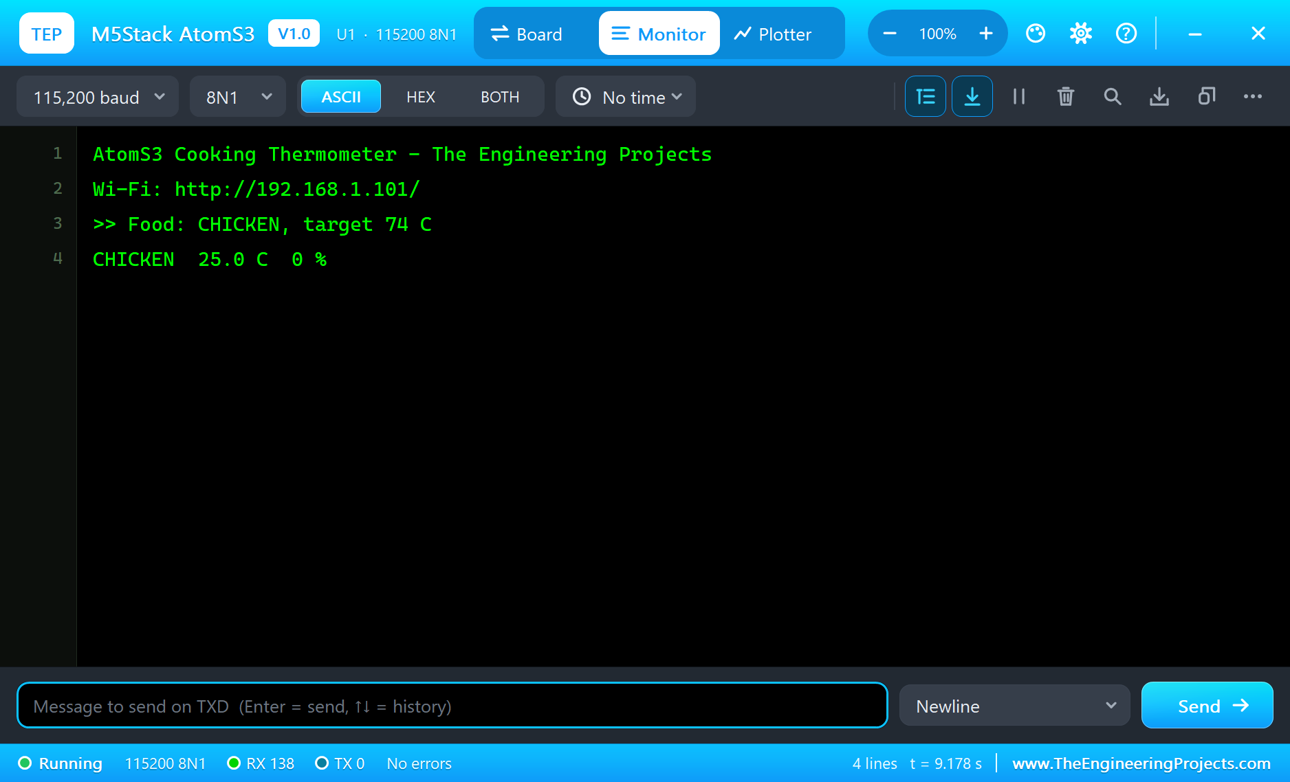
The Food Warms Up
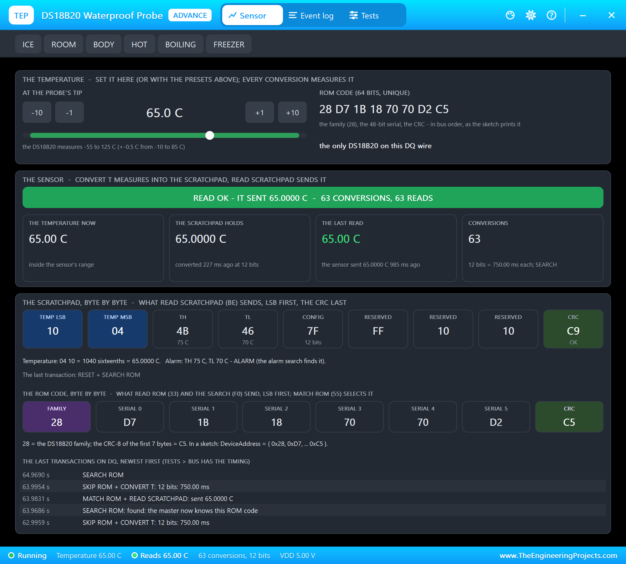
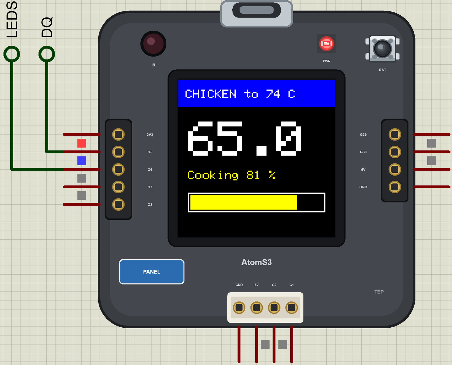
Click +10 four times on the probe's window. The food is now at 65 C, which is 81 % of the way, so six LEDs are lit: four blue and two amber. The screen and the phone follow within a second or two:
Ready
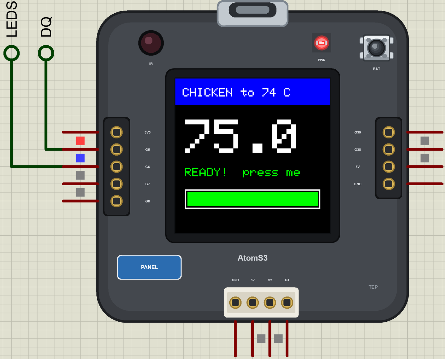
Click +10 once more. At 75 C the chicken has passed its target. The screen says READY, the whole stick turns green and starts to blink, and the monitor prints the moment:
The Phone
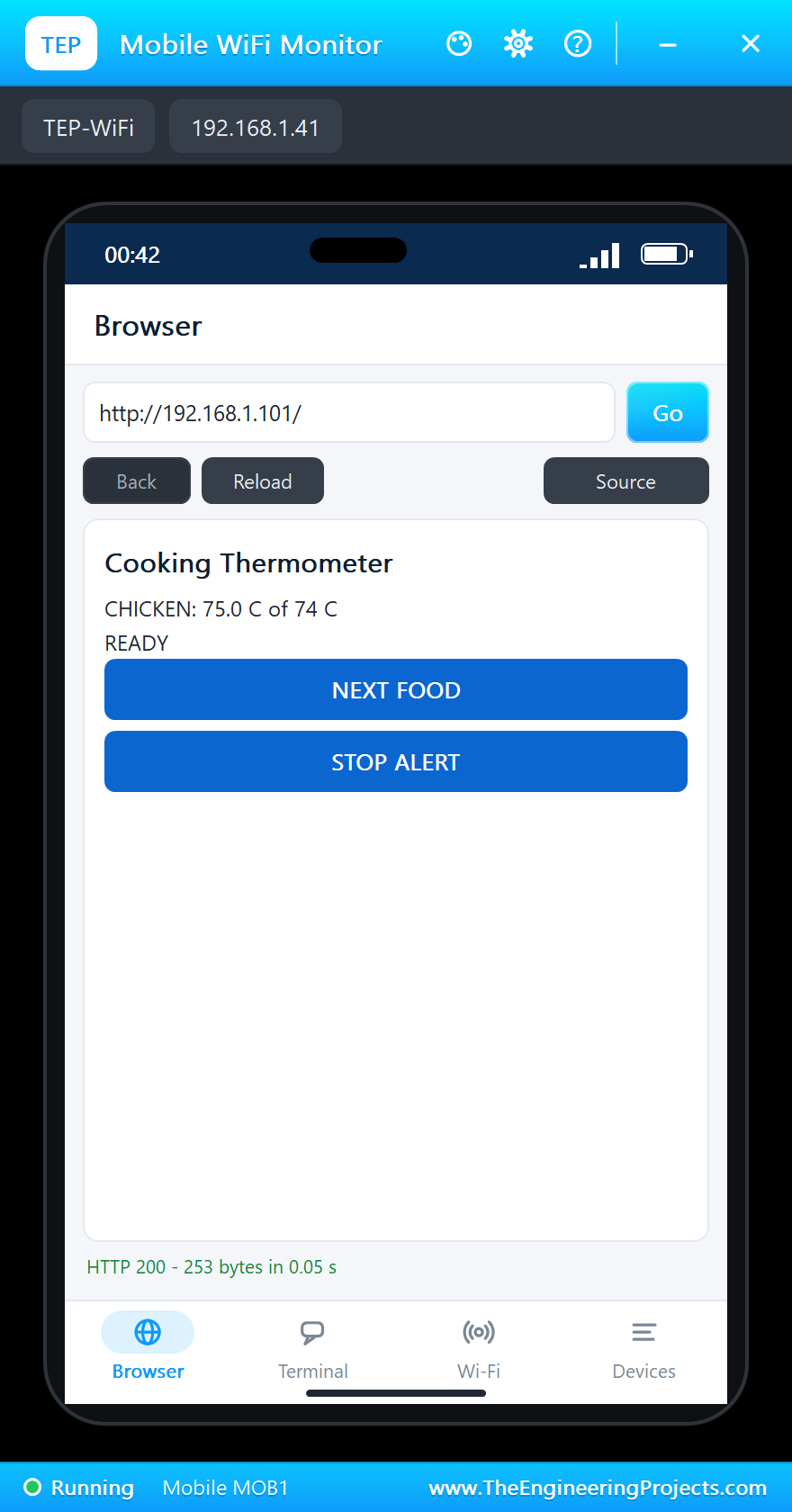
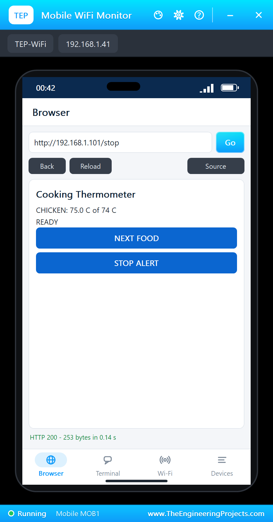
Click ESP32 U1 on the phone. The page shows the food, the temperature and two links. Tap STOP ALERT. The blinking stops, and the screen and the phone agree at once. A press on the screen does the same job:
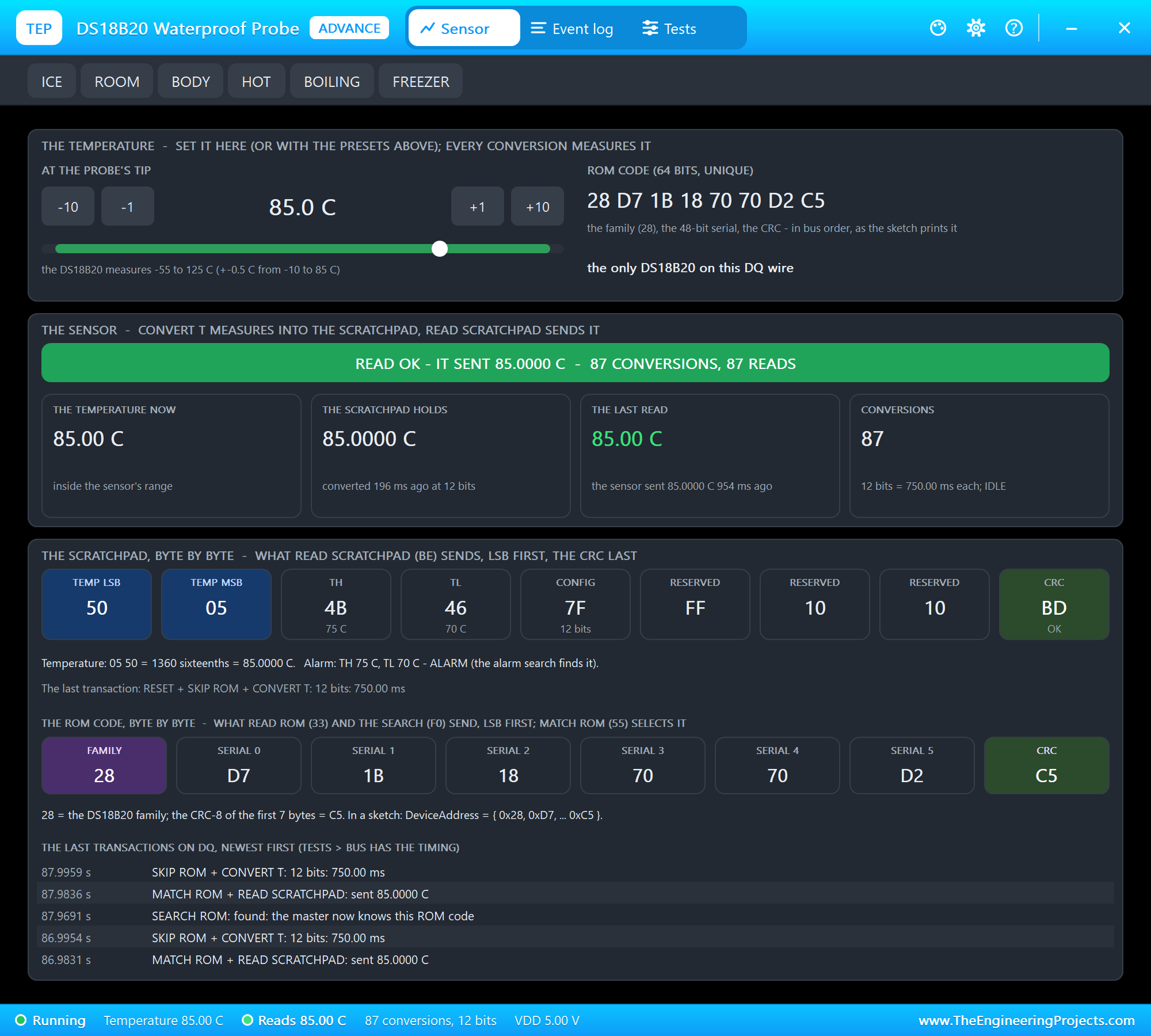
Too Hot
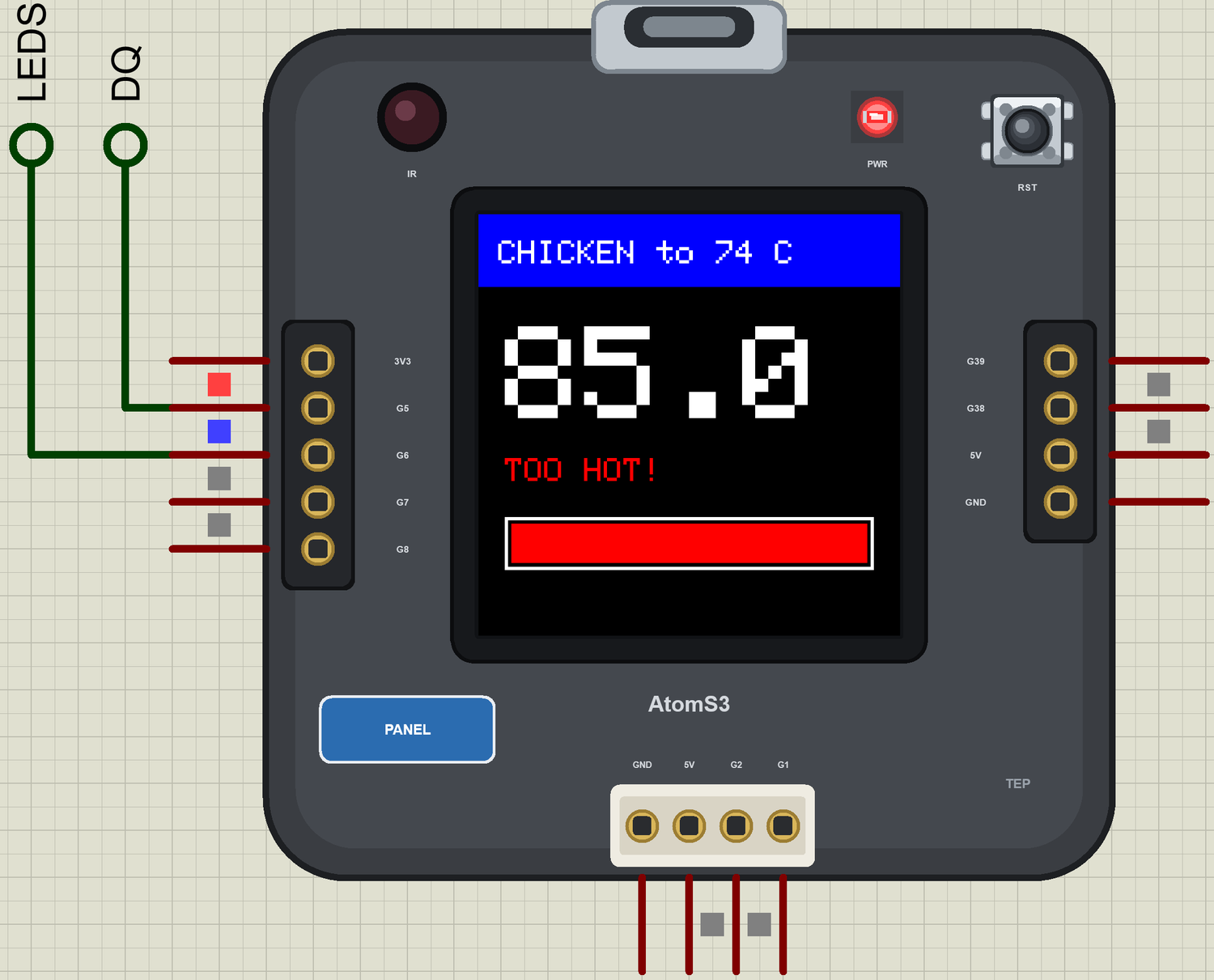
Click +10 again. At 85 C the food is more than 8 C past its target, so the stick turns red and the screen warns you:
The Next Food
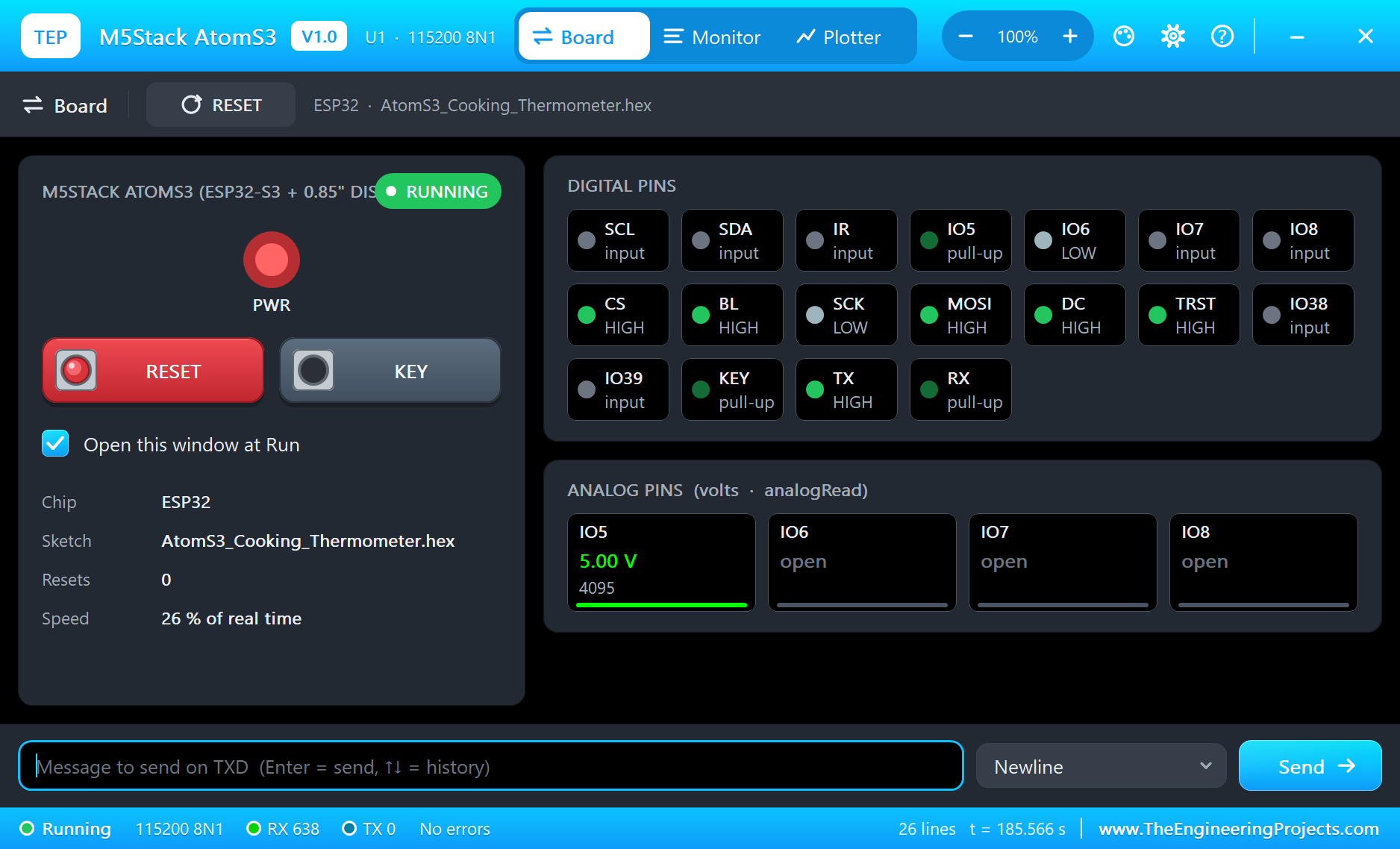
Click ROOM on the probe's window, and then click the screen of the AtomS3. That press is the key under it, so the sketch moves on to beef, with a target of 57 C, and takes the present temperature as its new starting point. The KEY button on the monitor's Board tab does the same. The monitor has followed everything:
CHICKEN  25.0 C  0 %
CHICKEN  65.0 C  81 %
>> READY: 75.0 C
CHICKEN  75.0 C  100 %
>> Alert stopped from the phone
CHICKEN  75.0 C  100 %
>> TOO HOT: 85.0 C
CHICKEN  24.0 C  0 %
>> Food: BEEF, target 57 C
BEEF  24.0 C  0 %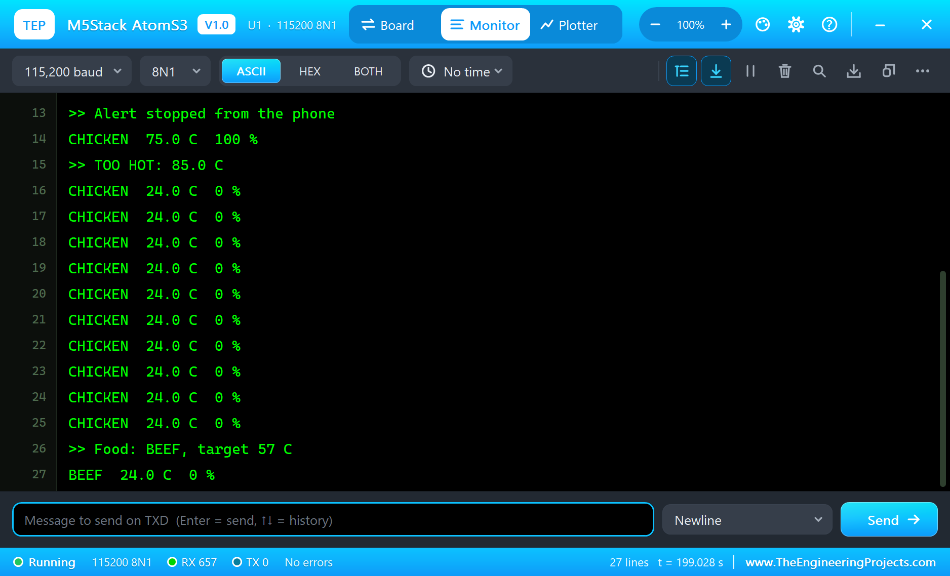
Try It Yourself
- Click BOILING or ICE on the probe and watch the stick follow.
- Add your favourite food to the
FOODSlist and rebuild the sketch. - Change
OVER_BYfor a tighter warning. - Use
analogWrite(TFT_BL, 80)to dim the screen when nothing is happening.
Ideas to Extend the Thermometer
- Estimate the minutes left from how fast the temperature is rising.
- Add a second probe on the same wire for the oven air: 1-Wire allows many sensors on one line.
- Send a message to a chat app when the food is ready.
- Put a small buzzer on G7 for the READY alert.
Your Own Sketches
Write the sketch in the Arduino IDE with the board M5Stack AtomS3 (TEP Proteus), use Sketch > Export Compiled Binary and set the part's PROGRAM property to the .hex. The pin names are in the variant, so your sketch stays short. Copy the GC9107 class from the demo for the display. On a real AtomS3 use the same pins with Espressif's "esp32" package.
Things to Know Before Using a Real AtomS3
- Use 3.3 V logic: the ESP32-S3 pins are not 5 V tolerant, so on a real build connect the probe's supply and the pull-up to 3V3, not 5V.
- Drive the LEDs carefully: WS2812 LEDs want 5 V power, and a 3.3 V data line can be marginal, so a level shifter is a good idea on a long stick.
- Enter download mode: hold the reset key for about two seconds, until the inside green LED lights, if the board does not take a new sketch.
- G38 and G39 are shared: they carry the MPU6886 on the inside bus, so keep them free if you want the motion sensor.
- Keep it away from the heat: the cube is plastic, so only the probe goes near the oven.
Properties of the M5Stack AtomS3
| Property | What it does |
|---|---|
| PROGRAM | the sketch: a .hex from TEP Boards for Proteus (board "M5Stack AtomS3") |
| WIFISSID, WIFIPASS | the router in range (TEP-WiFi, 12345678) |
| MONITOR, BAUD, AUTOOPEN | the built-in serial monitor: on, its baud rate (115200), open at Run |
Troubleshooting
- The display stays black: set
TFT_BLHIGH, thenSPI.begin(TFT_SCLK, -1, TFT_MOSI, TFT_CS)and the class'sinit(). - The colours look wrong: keep
ST77XX_INVONin the start-up list. - The key does nothing: use
pinMode(BUTTON_A, INPUT_PULLUP); a click on the screen is the key. - The probe reads -127: check the 4.7 kohm pull-up on DQ and call
probe.begin(). - The LED stick stays dark: call
stick.begin(), andstick.show()after setting the colours. - The phone shows the Welcome page: click ESP32 U1 in its list of devices.
- A number goes wrong above 32767: int is 16 bits in the simulation - use long.
Limitations of the Simulation
- Your sketch gets 8 KB of RAM in the simulation, and there are no FreeRTOS tasks and no second core.
- The MPU6886 and IR light are not modelled. Bluetooth is not modelled.
- M5Unified and M5GFX do not run on this part: use the pins directly.
- AtomS3 is a name of M5Stack and ESP32 of Espressif Systems; this library is not made or endorsed by them or by Labcenter.
- Tested in Proteus 8.5 in October 2026 (the demo as shipped, about 200 s of simulation). Proteus 7 is not supported.
So, that was all about the M5Stack AtomS3 Library for Proteus. I hope it helps you try your ideas for this tiny cube before you buy one - the display, the key under the screen, the Grove socket and Wi-Fi in one simulation. If you have any questions, ask in the comments and I will help you out. Till the next tutorial, take care and have fun!