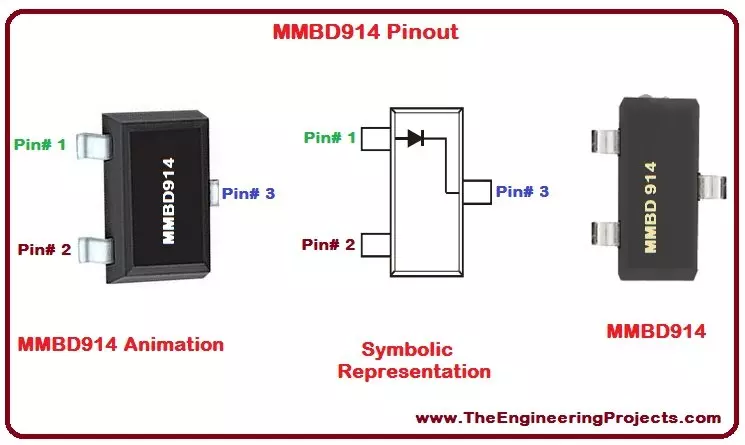
Hello everyone! I hope you all will be absolutely fine and having fun. Today, I am going to share my knowledge about Introduction to MMBD914. MMBD 914 is basically a switching diode. A switching diode has the functionality similar to the switch. Like an open switch, MMBD 914 has a high resistance for the particular applied voltage.
Switching diodes are usually used in different device e.g. ring modulation. The right switching diode can be chosen keeping in mind our requirements e.g. reverse recovery time, power dissipation and maximum peak current etc. I have also written an article on another switching diode, Introduction to 1N4148, and this my second article on switching diodes. MMBD-914 has a vey wide range of applications including high spee ...
Hello everyone! I hope you all will be absolutely fine and having fun. Today I am going to elaborate you about Introduction to L298. L-298 is an Integrated Circuit (IC) available in two type of packages now a days which will be given later. L 298 is a dual full bridge driver that has a capability to bear high voltage as well as high current. It receives basic TTL (Transistor Transistor Logic) logic levels and is able to operate the different loads such as DC motors, stepper motors, relays etc. You should also have a look at Introduction to L23D.
L-298 has two enable input to control any device by enabling or disabling it. L 298 IC is most commonly used to make motor drivers or motor controllers. These motor controllers can be controlled by any ...
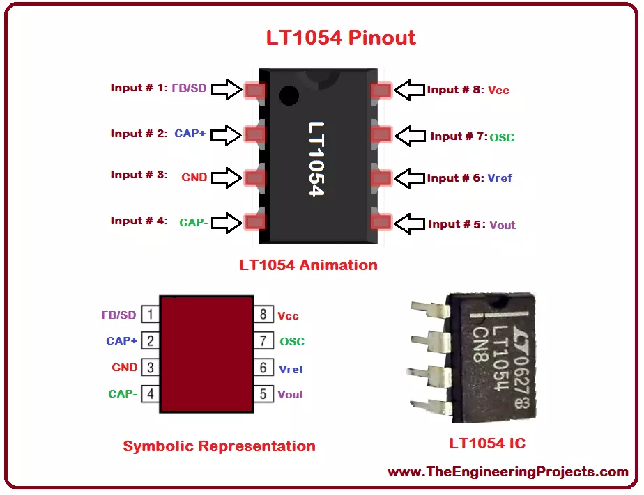
Hello everyone! I hope you all will be absolutely fine and having fun. I am going to elaborate you on Introduction to LT1054. It is a monolithic device. LT-1054 is also known as voltage regulator and bipolar capacitive voltage converter. Its mean feature is that it provides very low voltage losses as compared to the other common converters. LT 1054 also provides large output currents in comparison to general converters. It provides a voltage drop of around 1.1V while operating at 100mA.
LT 1054 provides us with a feature of regulation. This feature was not available in earlier voltage converters. We can get a regulated output just by inserting an external resistance. We can shut down LT-1054, if we ground its feedback terminal. Its internal osci ...
Hello everyone! I hope you all will be absolutely fine and having fun. Today, I am going to share my knowledge about Introduction to 74HC245. 74HC 245 is a eight (8) bit transceiver. It has three (3) output states. 74HC-245 is designed for a-synchronous transfer of data between different data buses. The external timing requirement can be reduced by the implementation of control function. You should also have a look at Introduction to 74HC595.
There are two internal amplifiers in 74HS 245. They are named as A and B. Data is transferred from A amplifier to B amplifier and vice versa. Hence two way communication is done in 74HC-245. This communication depends upon the logic level on the direction control input (DIR). Out enable pin (OE) is used to ...