Hello friends, i hope you all are fine and enjoying. In this post i am going to share a new project tutorial, in which we will see how to design an 11 Level Cascaded H Bridge Inverter. If you recall my previous tutorial, in which we saw the design and working applications of 11 Level 3-phase Capacitor Clamped Inverter, then you can see its exactly the same project but only we are having a different approch in it, instead of using Capacitor clamped we are using cascaded H bridge Inverter in this project.
In this project we again are going to design an inverter but the only difference is The Implementation Technique. In that project we used Capacitor Clamped technique to get High Voltages inverted AC and now in this project, we will use Cascaded H-Bridge technique to design an Inverter. We have designed this Cascaded H bridge Inverter project in Simulink MATLAB. So i will explain this project tutorial in steps. First of all we will discuss the block diagram of the project, which we have made in Simulink. Then we will discuss the internal structure and the components which are implemented in the block diagram. And in the end we will see the applications of the cascaded H-Bridge inverters. I think this was enough for introduction and Now let's get practical and without wasting any time i think we should move towards the designing of the cascaded H Bridge 3-phase inverter.
11 Level 3-Phase Cascaded H Bridge Inverter
- A cascade H Bridge Inverter is a power electronic device, built to synthesize a desired AC voltage from several level of DC voltages.
- Cascaded H Bridge inverter can be implemented by using only a single DC source or capacitors or multiple DC sources.
- A standard cascade multilevel inverter requires 'n' DC sources to produce '2n+1' levels.
- The beauty of this system is that it can allow us to gain the desired levels of AC without using any type of Transformer.
- It allows us to simultaneously maintain the DC voltage level of the DC source and choose a fundamental frequency switching pattern to produce a nearly sinusoidal AC output.
- The block diagram of the Cascaded H Bridge Inverter designed in Simulink MATLAB is shown in the image given below:
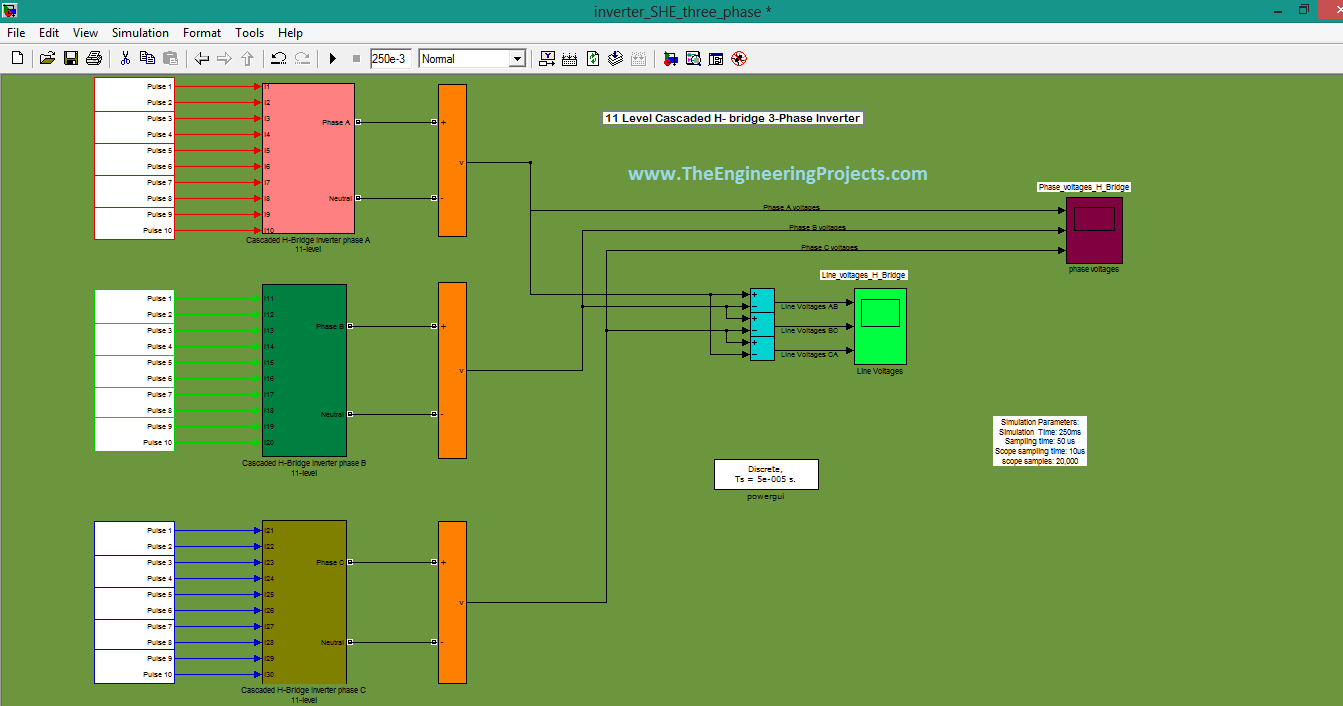
- From above figure, you can see that we have on the extreme left side we have inputs of the systems and they are numbered as 'pulse'.
- Since we are going to design a multilevel inverter, which is a 11 Level inverter and to get that much levels, we also need multiple DC inputs.
- In this system, we have 30 DC inputs and they are numbered as 'pulse1-pulse30'.
- From the title of the project, you can understand that we are going to design a 3-phase inverter and for that we must have 3 control units to get three phase voltages.
- All the inputs are going to three big blocks which are named as ' Cascaded H-Bridge Inverter'. If you double click on that block then, a new window will open which will show the internal mechanism of this big block.
- This window is shown in the image given below:
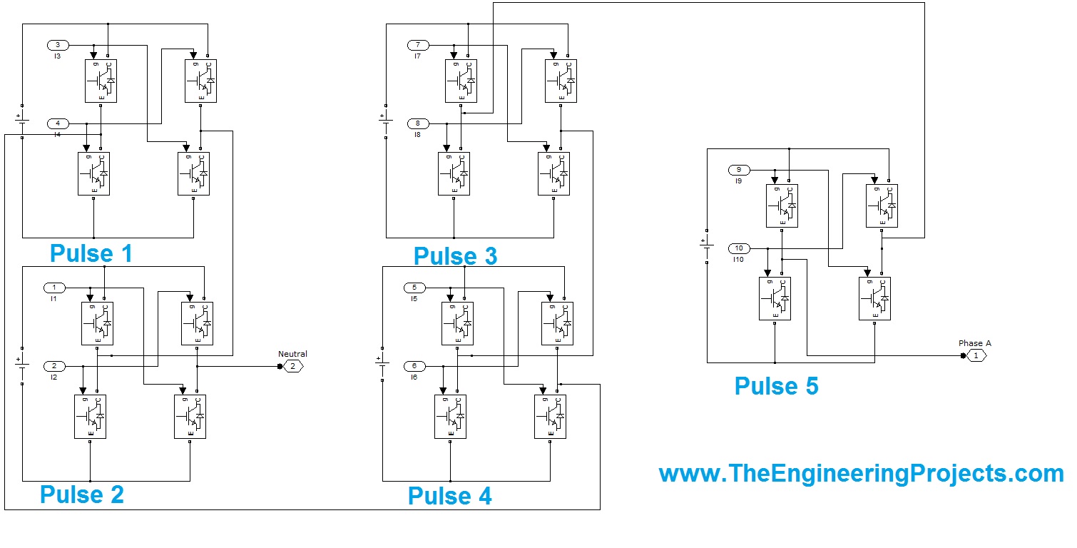
- The above figure is very important and it is showing what actually is happening in that block. Since the components encrypted in each block are large so the above figure is showing half of the components.
- 10 inputs are connected to each block and in the above shown block we have 5 inputs.
- Every input is connected to a H shape bridge. In every H-shaped bridge, we have 4 sub-blocks. In order to under the mask of the sub-blocks, Double click on them and a new window will open, which will be representing the internal structure of sub-block.
- That small window is shown in the image given below:
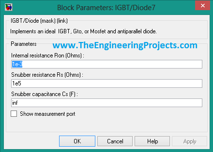
- Now from the above figure, you can see that every sub-block contains an ideal IGBT, Gto or MOSFET and antiparallel diodes.
- In these H-bridges we have implemented MOSFET transistor for switching. Reason is that they have mush fast response and are capable to perform switching at high speed.
- Below are some parameters of transistors, which are fabricated in sub-blocks.
- An important thing to note here is that for MOSFET 'Snubber Resistance (Cs)' is infinite in OFF state. This is because in OFF state it doesn't allow the current to pass through it.
- Once MOSFET is triggered then it will keep on conducting and after that we will have to stop it manually.
- Now if you again focus the first block diagram then, you will observe that each block is giving only value of phase voltages at its output.
- From three blocks, we get three phase voltages and then to measure these voltages, we have 2 types of measuring devices.
- First type of voltmeter will measure the phase voltages and you can see that all the three phases are connected to that instrument.
- Phase voltage is the potential difference between a single phase and neutral wire. Since no neutral wire is connected to this instrument and the meter will take the system's neutral wire to measure the voltages.
- The other meter measures the Line voltages. Line voltages are the potential difference between any two phases. At our meters input we have Line Voltages like AB, BC and CA.
RESULTS
- We have connected two different types of voltmeters in our system. One will give the graphical representation of phase voltages and the other will give the graph of Line voltages.
- The graph of phase voltages is given below in the image:
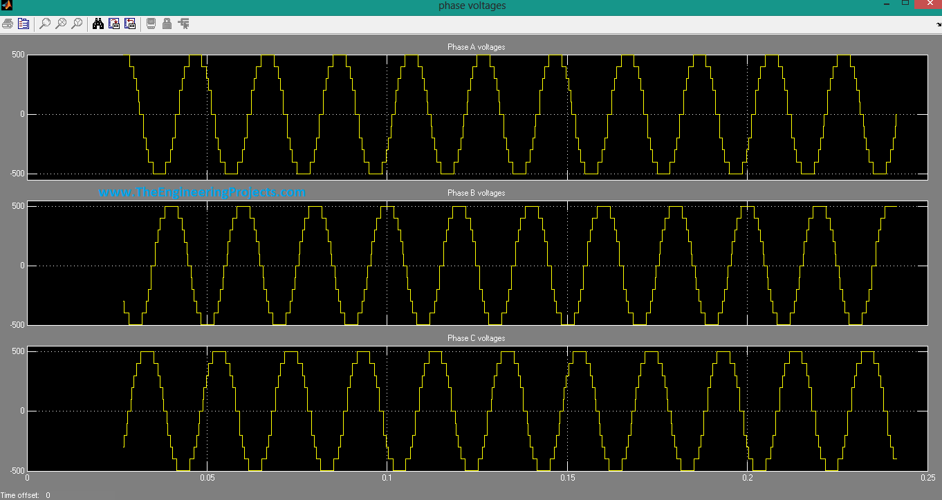
- The above graph is representing the phase voltages of all the three phases, which we have generated in our system.
- You can see that all the three phases are at an angle of 120 degrees to each other.
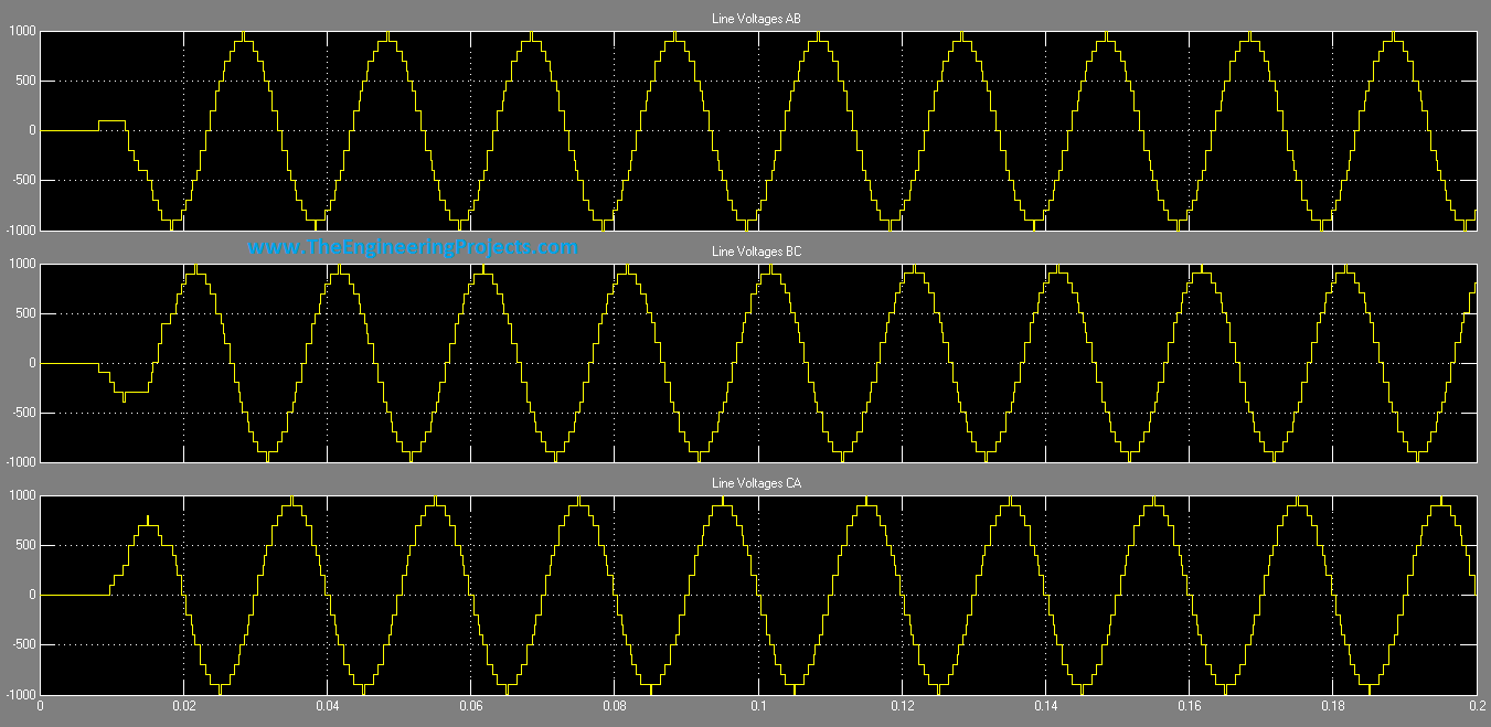
- The graph of line voltages is shown in the image given below:
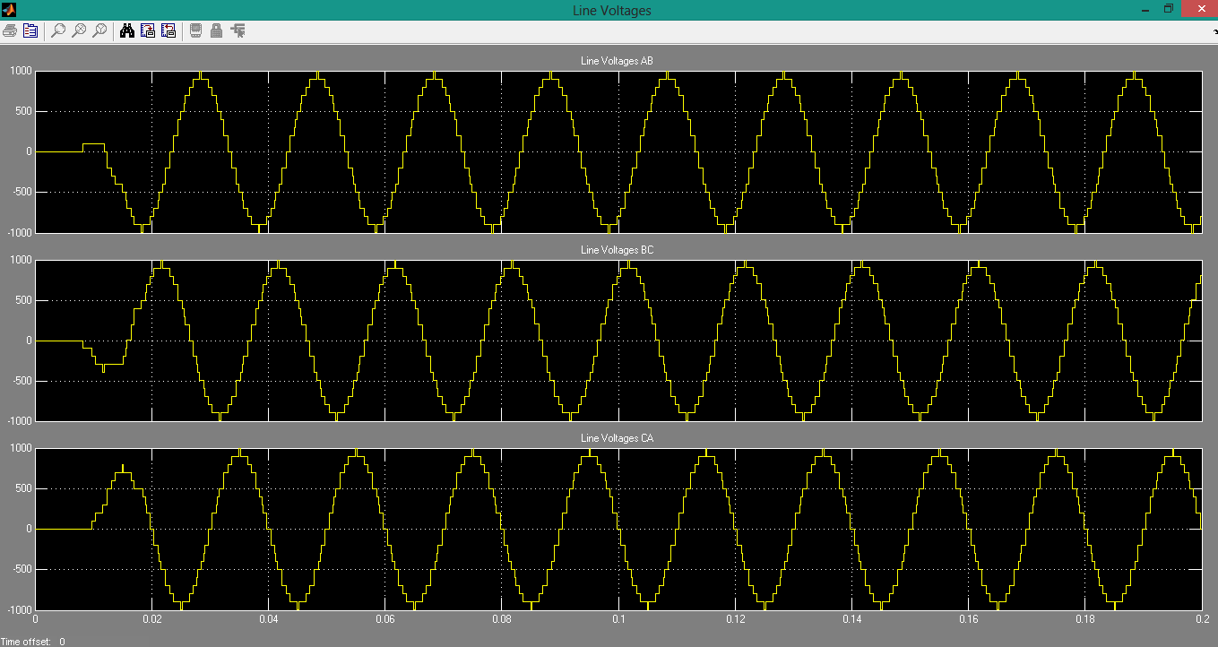
- The above graph is showing the 3-phase line AC voltages.
- You can see that some cornered square wave is obtained at output. Corners are appearing in output wave due to switching of MOSFET transister, we have used in our project.
- A proper filter circuit can eliminate this flaw and a fine AC can been obtained at output.
Alright friends, that was all from today's post. I hope you guys have enjoyed this H Bridge Inverter. If you have any question then ask in comments and i will try my best to resolve the issue. For more tutorials stay tuned. Till next tutorial Take Care !!! :)


