

Its a very simple project so the programming level is very basic. We will just add some LEDs on all pins of PortB of PIC16F877a and then we will program it in such a way that these LEDs will blink in different pattern, we can also change the speed of blinking by adding a delay.
I will explain the whole code but if you got any problem may ask in comments.I will recommend you guys to do this project, I know a beginner can't make this project work in first attempt but when you do it, you will make mistakes and will learn a lot. So let's start the LED Blinking Project using PIC16F877a:
LED Blinking Project on PIC Microcontroller
- You can download the Proteus Simulation and Programming code for LED Blinking Project using PIC16F877a, by clicking the below button:
[dt_default_button link="https://www.theengineeringprojects.com/PICProjects/Led Blinking Project with PIC Microcontroller.rar" button_alignment="default" animation="fadeIn" size="medium" default_btn_bg_color="" bg_hover_color="" text_color="" text_hover_color="" icon="fa fa-chevron-circle-right" icon_align="left"]Download Proteus Simulation & Code[/dt_default_button]
- Now let's design this project so that you can understand how its done.
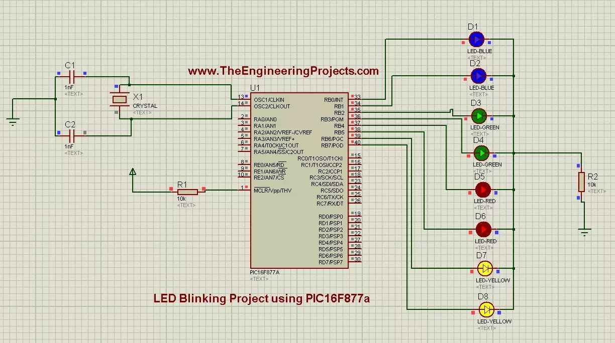
- First of all, design a simulation of LED Blinking Project using PIC16F877a in Proteus as shown in below figure:

Components Used:
These components are used while designing this simulation:- PIC16F877a.
- LED. ( We need 8 LEDs )
- Resistors. ( We need 2 resistors of 10k ohm )
- Capacitors. ( We need 2 capacitors of 1nF )
- Crystal Oscillator. ( 16MHz )
Working Principle:
- The circuit on the left side of PIC is its basic circuit, we need this circuit in order to power up the PIC and to give it a frequency on which it operates. Like in this diagram, I have used crystal oscillator of 16MHz, which is its frequency of operating. You can operate it at different frequencies e.g. 4MHz ,10MHz , 16MHz, 20MHz etc.
- But keep this thing in mind that if you change the oscillator then you must change the capacitors as well e.g. for 16MHz the capacitors will be of 33pF.
- Vdd for PIC is 5V , if you have a 5V battery then its cool but mostly adapters are of 12V. So if you have 12V adapter then use 7805 which converts the 12V into 5V.
- Now come to the circuit on the right side of the PIC, these are simple LEDs which I have connected with PortB of PIC Microcontroller.
- On the other side of these LEDs is a resistor just for current control and then a GND (ground).
- Now when we make any of these pins high then respective LED will turn ON and when we make that pin low, LED will turn OFF.
- Pin High means its at 5V and LOW means its at 0V.
- Now let's come to the programming part.Open your MikroC Pro For PIC Compiler and create a new project in it.
- Make sure that you select PIC16F877a in Device Name and keep the frequency to 16MHz.
- Watch the video, if you got into any trouble, its attached at the end of this article.
- Now place the below code in your MikroC Pro for PIC Compiler:
// ************ LED Blinking Project using PIC16F877a
void main() {
trisb= 0x00;

while(1)
{
        portb = 0x00;
        delay_ms(2000);
        portb = 0xFF;
        delay_ms(2000);
}
}
- Now let me explain the code, it's a very simple code just five to six lines.
- void main () This is the main function of program, the compiler always come straight to this part and leaves the rest it will execute only what is written under its braces.
- trisb = 0x00; This code will tell the compiler to use the pins as output. If we were using a sensor on any pin then we have to make it 1.
- while(1) This one runs continuously means pic will execute the code with its braces forever and it never stops.
- and in the next two lines we make the pin high and then low which is connected to the LED so now the LED will turn ON and then OFF continuously.
- You can also increase the delay between these lines if you want to increase the duration of ON / OFF.
- Now Build your project to get the hex file.
- Upload this hex file in your Proteus Simulation and then run your simulation.
- If everything goes fine then you will get something as shown in below figure:
- Looking Pretty, isn't it ? :D
- Here's the video which will give you better idea of its working:
I have tried my best to explain it in full detail but if still you got any problem or anything left then ask in comments and I will explain it to you. So, that was all about LED Blinking Project using PIC16F877a.
Stay Blessed .... ALLAH HAFIZ :))
Reply
TRIS is a special function register in PIC if you keep this register high it means your that PORT will be input and if you make it low your PORT will be OUTPUT.
@panchi Ya bro i loved it too , its actually a flash image and working really kool, I am thinking of adding it on the home page in future .... what you say ?? :)) Reply
void delay(unsigned int itime )
{
unsigned int i,j;
for(i=0;i<itime;i++)
for(j=0;j<135;j++);
}
This is the delay routine it must be added at the end of code outside the main code and then to use it in my code i will call it as follows :
PORTDbits.RB0 = 1;
Delay(1000);
PORTDbits.RB0 = 0;
If you still feel any problem ask me. Reply
Reply