


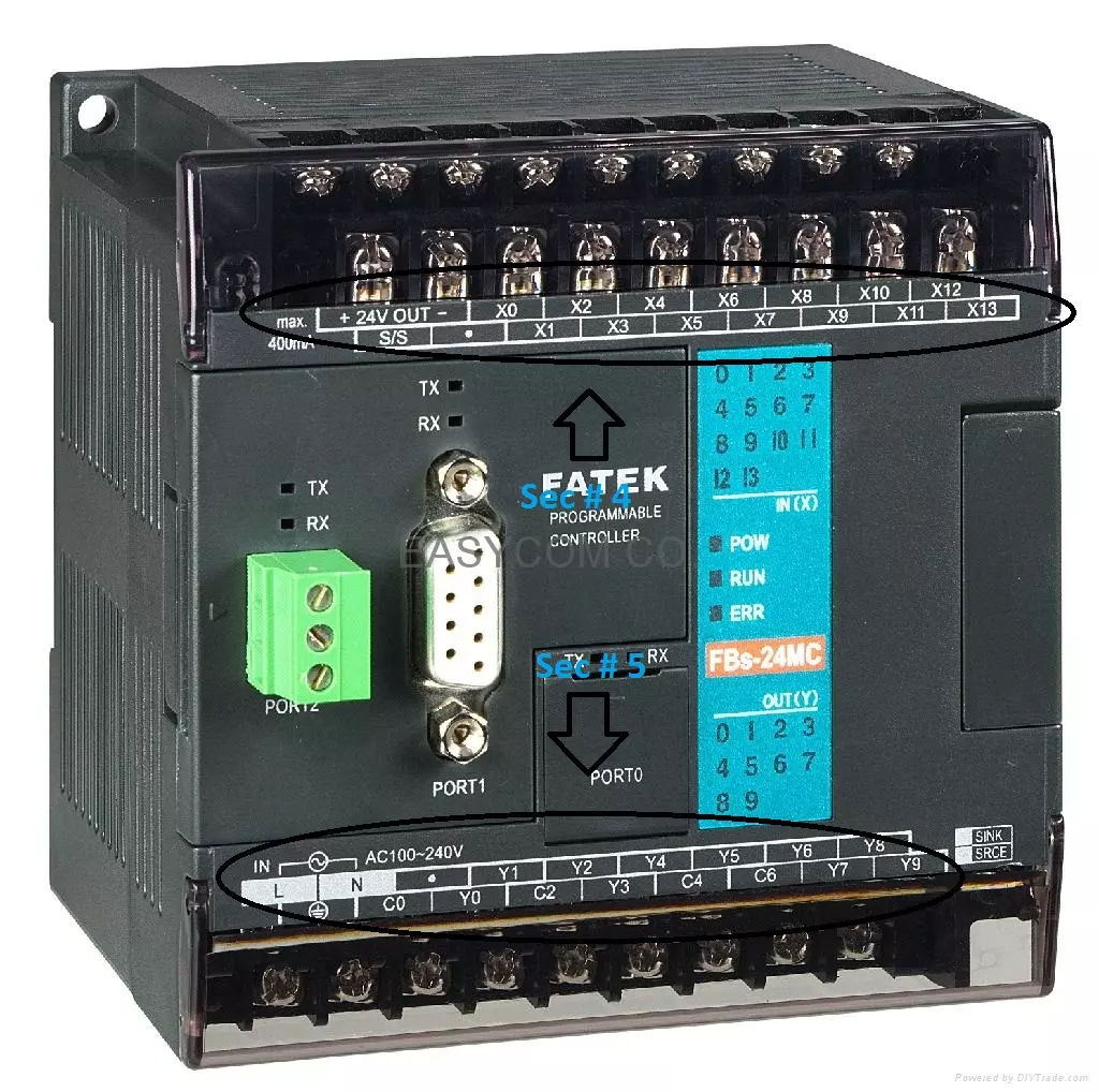
Hello friends! In our Introduction to PLC , we looked at the controller, its terminals and the difference between a program command and an electrical output. Today we will connect those ideas using ladder logic. We will start with one input and one output, then build AND, OR and NOT conditions before adding a simple memory circuit. Ladder diagrams look like relay circuits, which makes them approachable once you understand what their symbols mean. However, the diagram is a program. A contact symbol tests a stored Boolean value; it is not a physical switch carrying voltage through the screen. Keeping that distinction clear will prevent many common wiring and programming mistakes. The retained examples use X addresses for inputs and Y addresses for outputs, following the style of the original ...