


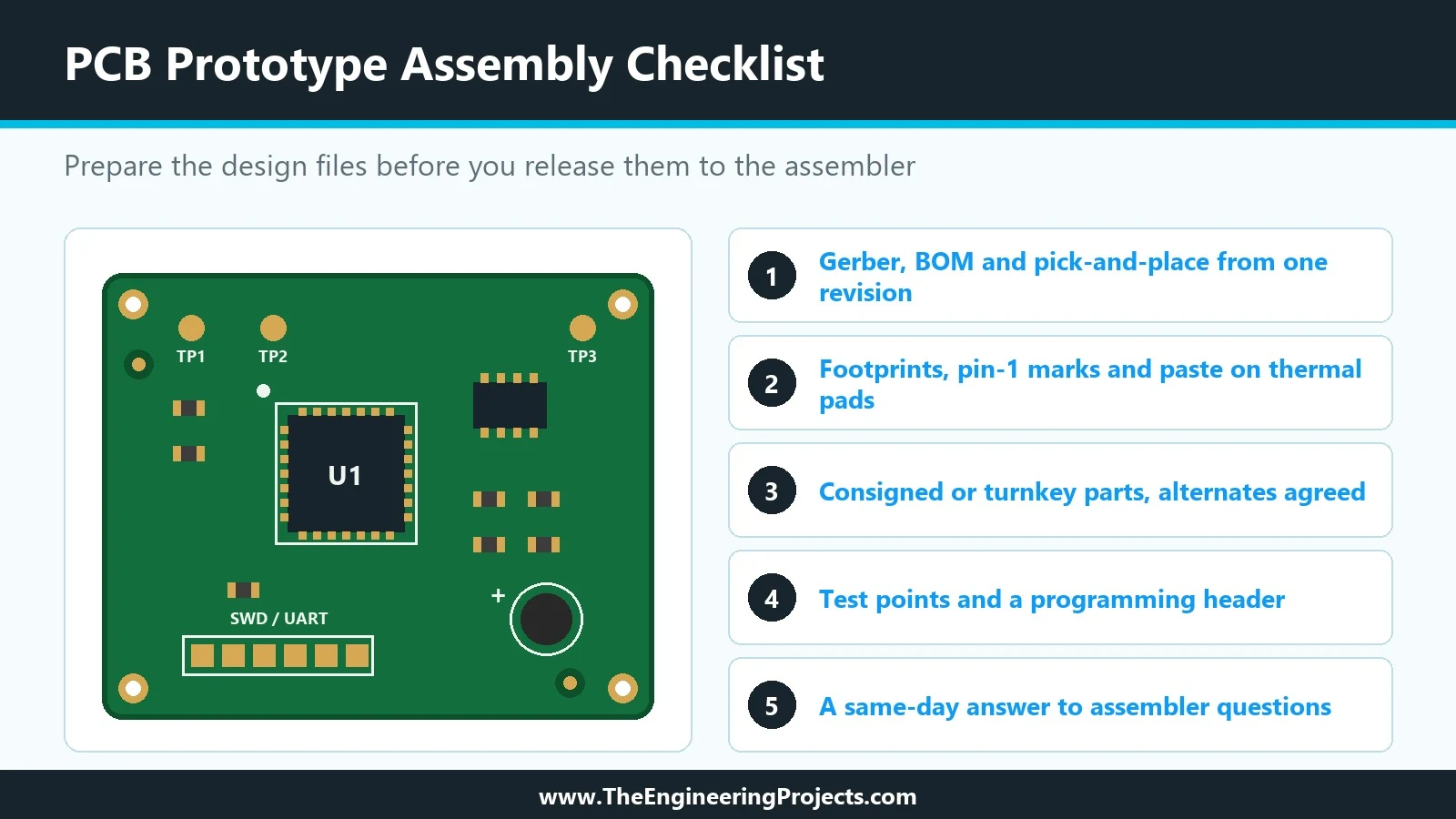
Figure: Assembled boards and display panels laid out after a production run. Many hardware projects, including Arduino-based and embedded designs, stall at the prototype stage. The schematic works on paper, the layout looks clean, and the simulation runs without errors. Then the assembled boards arrive with misplaced parts, missing components, or no practical way to test them. Most of these delays come from incomplete files and overlooked details rather than from the factory itself. Moving from a design file to a working prototype involves more coordination than many engineers expect on the first build. The assembler needs consistent data, clear polarity marks, and a realistic plan for how questions will be answered. This checklist covers the points that most often cause problems and how t ...