


How to Prepare a PCB Design for Prototype Assembly: A Practical Checklist


Many hardware projects, including Arduino-based and embedded designs, stall at the prototype stage. The schematic works on paper, the layout looks clean, and the simulation runs without errors. Then the assembled boards arrive with misplaced parts, missing components, or no practical way to test them. Most of these delays come from incomplete files and overlooked details rather than from the factory itself.
Moving from a design file to a working prototype involves more coordination than many engineers expect on the first build. The assembler needs consistent data, clear polarity marks, and a realistic plan for how questions will be answered. This checklist covers the points that most often cause problems and how to address them before you release the files.
Match the Files to the Same Revision
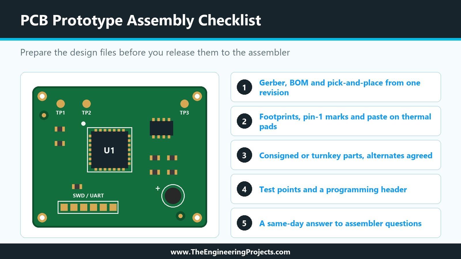
The Gerber files, BOM, and pick-and-place (centroid) file must all come from the same design revision. A common failure is an updated schematic that never made it into the coordinate file, so components land on the wrong pads. Another is a BOM that lists parts by description only, without a full manufacturer part number. When the assembler has to guess which exact component you intended, the build stops until you clarify it. Before you release the package, confirm:
- Gerber, BOM, and pick-and-place share the same revision and date
- Every line item has a manufacturer part number and a preferred manufacturer
- Polarity and pin-1 marks are visible on the silkscreen for all polarized parts
- The centroid file uses the same origin and units the assembler expects
It also helps to include a short readme or fabrication note that lists any non-standard requirements, such as a specific surface finish, controlled impedance on certain nets, or a preferred panelization method. These notes prevent the assembler from applying default settings that do not match your intent.
Check Footprints and Manufacturability
A QFN, connector, or fine-pitch part that looks correct in the library can still have the wrong pad size or pin order. These errors are difficult to catch in a schematic review and expensive to fix after the stencil is made. Even a small pad-size mismatch can cause tombstoning or insufficient solder on one side of a passive component.
A structured review focused on assembly catches most of them. Checking footprints against the latest datasheets, verifying spacing around fine-pitch ICs for rework tools, and confirming solder-mask clearance on exposed pads takes less time than debugging a swapped pin on the first boards. Thermal pads on QFN and power packages also need attention: too little paste causes poor thermal and electrical contact, while too much can float the part.
If you want a second look before fabrication, a PCB design review for assembly can flag footprint, spacing, and stencil issues early. The review is most useful when it happens before the Gerbers are finalized, so changes can still be made in the layout tool.
Decide How Components Will Be Supplied
You can consign the parts yourself or ask the assembler to source them (turnkey). Consigning gives you more control over specific manufacturers and lot traceability, but it requires clear labeling that matches the BOM line items. Mixed or unlabeled reels slow the line more than most people expect. Each reel or tray should carry the BOM line number, manufacturer part number, and quantity so the operator does not have to cross-reference multiple documents.
If the assembler is sourcing, confirm early whether critical parts have approved alternates. A component that was in stock when you finished the design may be unavailable by the time the boards are ready. Agreeing on alternates (and who approves them) before the build starts avoids multi-day holds. For prototypes it is often practical to consign the few long-lead or single-source parts and let the assembler buy the passives and common ICs.
Additionally, consider moisture-sensitive devices. Parts that require baking or dry storage should be identified in the BOM notes so they are handled correctly on the line.
Plan for Test and First-Article Checks
Prototype boards often power up, then leave you with no easy way to probe key nets or program the microcontroller. Adding a few test points and a clear programming header costs little and saves time when the first boards arrive. Place test points on power rails, critical analog nets, and any signals you expect to debug. A simple 1×4 or 1×6 header for SWD or UART is usually enough for embedded prototypes.
During first-article inspection, check polarity of polarized parts, orientation of ICs, and basic continuity on power and ground. If the design includes multiple voltage rails, verify that each rail comes up in the expected order and stays within tolerance under light load. Prototype PCB assembly that includes AOI and simple electrical testing can catch opens, shorts, and placement errors before the boards ship, so you spend less time debugging assembly defects on your bench.
Agree in advance how questions will be handled. If the assembler finds a polarity ambiguity or a missing part, a same-day reply keeps the job moving. A slow response turns a one-day clarification into a multi-day hold.
Panelization and Edge Features
For small prototype quantities, panelization is often optional, but it still affects handling. If you do panelize, define mouse-bite or V-score locations so the boards can be separated without damaging edge components. Keep connectors and tall parts away from the score lines. Fiducials and tooling holes should be present if the assembler requests them; many lines can run without them for small jobs, but including them removes one variable.
Common Reasons Prototypes Are Delayed
- Documentation from different revisions
- Incorrect footprints or missing pin-1 marks
- Unlabeled or mixed consigned parts
- No test points or programming access
- Slow replies to assembler questions about polarity or missing parts
- Unapproved component substitutions discovered only after placement
None of these are unusual. They are the normal friction of turning design files into working hardware. Checking them before release removes the most frequent causes of delay and reduces the number of emails required during the build.
Next Steps
Once the files are consistent, the footprints have been verified, and the test strategy is clear, working with an assembler experienced in prototype volumes reduces the back-and-forth. Clear documentation and a defined channel for questions matter as much as the manufacturing process itself.
If you are preparing a design for assembly and want help with file review or a build quote, AimPCB can review the package and outline the practical next checks. Sending the Gerbers, BOM, and pick-and-place together with a short note on quantity and any special requirements is usually enough to start.

Comments
0