


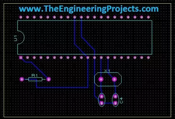
Hello friends! Today we will move from a circuit diagram to a printed circuit board using Proteus ARES. We will use a small PIC16F877A circuit so that placement, connectivity, and routing remain easy to follow. The same sequence of decisions applies when you later design a larger board. Proteus schematic capture describes which component pins belong to each electrical net. PCB layout turns those connections into physical pads and copper tracks. A completed route is useful only when the footprint, pin mapping, power connections, and manufacturing rules are also correct. We will follow the original illustrated workflow: prepare the schematic, transfer its connectivity, define the board edge, place components, and route the board. We will then add the checks needed before sending a design for ...