


Introduction to TIP3055


Introduction to TIP3055
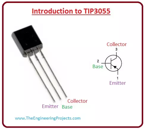
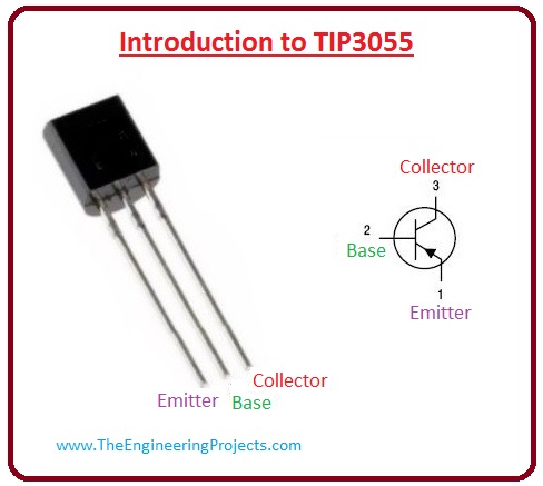
- TIP3055 is a silicon epitaxial-ignoble NPN transistor, which is assembled in TO-218 malleable parcels. It is the best device for power swapping circuits, parallel and series controllers (regulators), output phases and high power amplifiers.
- It is prevailing in TO-247 pouring and it frequently used varied amplifiers initiatives.
- This module uses moderate power during its working, it uses 70 voltage across emitter and collector. It consumes fifteen amperes of current at the collector.
- It is the finest option for advanced steadfastness audile amplifier output point.
- This component has termination voltage Vceo (IB =0) 60 volts.
- It has a unique extensive liability and particular excellence formation.
- Its Stowage temperature is -65 to 150 C and maximum working intersection temperature is 150 C.
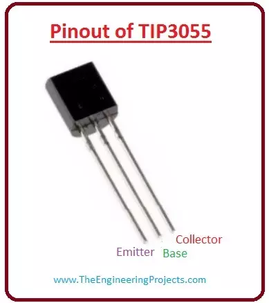
Pinout of TIP3055
- These are the main pinout TIP3055 which are well-defined beneath.
-
Lest see a diagram of the pinout.Pin# Type Parameters Pin#1 Emitter The emitter is for an external drive of current. Pin#2 Base The base administers the biasing of the transistor. It vagaries the state of the transistor. Pin#3 Collector The collector is for the current inside drive. It is related to the load. 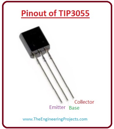
Entire Maximum Ratings of TIP3055
Now we discuss the rating parameters of TIP3055.| Symbols | Value | Parameters |
| VCBO | 100 V | The voltage across collector and emitter (IE = 0). |
| VCER | 70 V | The voltage across emitter and collector (RBE = 100 ?). |
| VCEO | 60 V | The voltage across emitter and collector at (IB = 0). |
| VEBO | 7 V | The voltage across the collector and base (IC = 0). |
| IC | 15 A | The current value at the collector. |
| IB | 7 A | The value of current at the base terminal. |
| Ptot | 90W | Dissipation power at Tc =25°C. |
| Tstg | -65 to 150 C | Storing temperature. |
| TJ | 150 C | Maximum Working intersection temperature. |
Electrical characteristics
These are some important electrical characteristics.| Symbols | Test Conditions | Parameters |
| ICEX | VCE = 100 V TC = 150 C | The value of collector cut-off current (VBE = -1.5 V). |
| ICEO | VCE = 30 V | The value of collector cut-off current (IB = 0). |
| IEBO | VEB = 7 V | The value of emitter cut-off current (IC = 0). |
| VCEO | IC = 200 mA | Collector-emitter supporting voltage (IB = 0). |
| VCER | IC = 200 mA | Collector-emitter supporting voltage (RBE = 100 ?) |
| VCE | IC = 4 A IB = 400mA IC = 10 A IB = 3.3 A | Collector-emitter permeation voltage. |
| VBE | Ic=4A VCE = 4 V | It is the voltage across base and emitter. |
| hFE | IC = 4 A IC = 10 A VCE = 4 V 20 VCE = 4 V 5 | It is DC current gain. |
Working of TIP3055
- Now we discuss the working of TIP3055 by a circuit. The corresponding circuit components and its connection are explained below let's discuss them with the details.
- This is the circuit of amplification of power in which I used TIP3055 and TIP2955 transistors as amplifiers which provides power up to 140RMS.
- This circuit is manufactured miniature and very modest, the bulwark portion is prepared by using IC ua741 or LM741 as op-amp.
- The ultimate transistor I have stated using TIP3055 and TIP2955 transistors, or you can elevate by adding some transistors or also swap with higher output power, for example using 2SC5200 and 2SA1943.
- We can power this circuit by balanced 45V voltage, power circuit arrangement and also PCB Layout are shown in the given diagram.
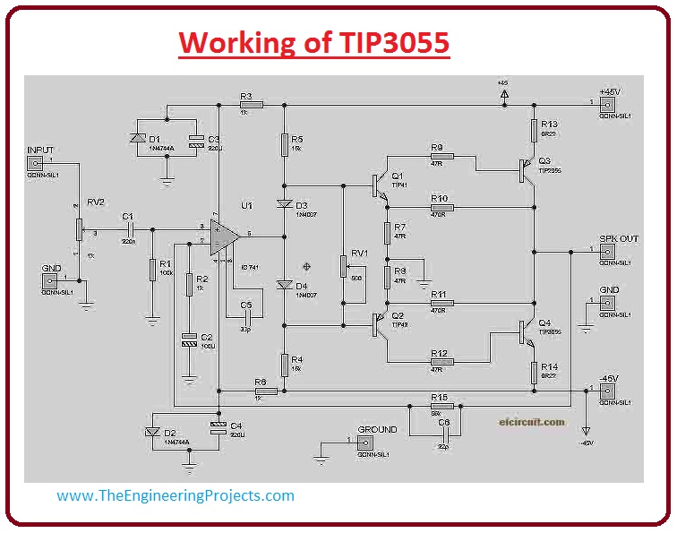
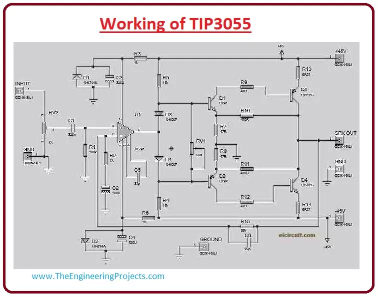
- The components which I used in this circuit is explained below with their rating values.
- R1=100K, R2=1k, R3=1K, R4=15K, R5=15K, R6=1K, R7=47R, R8=47R, R9=47R, R10=470R, R11=470R, R12=47R, R13=0, 22 - 0, 5R/5W, R14=0, 22 - 0, 5R/5W R15=56K, C1=220N, C2=100u/25V, C3=220u/25V, C4=220u/25V, C5=33p, C6=22p, RV1=TRIMMER 500R RV2=POTENTIOMETER 50K U1=LM741 / UA741 Q1=TIP41 Q2=TIP42 Q3=TIP2955/2N2955 Q4=TIP3055/2N3055
- If this amplifer circuit is not working properly then you should check input voltage.
- Output speaker has DC voltage whining, please regulate the trimmer RV1 till the DC Voltage comes out.
Applications of TIP3055
- These are some important applications of TIP3055.
- It is universal persistence transistor it can be used in different industrial projects.
- It is used as an Acoustic Amplifier.
×
![]()


