Hi friends, today we are going to learn a good technique to run multi outputs in sequence. In another word, when we have some output that is repeatedly run in sequence. In the normal or conventional technique of programming we deal with them individually or one by one which takes more effort in programming and much space of memory. So instead we can use a new technique to trigger these outputs in sequence using one instruction which will save the effort of programming and space of memory. In this article, we are going to introduce how to implement sequencer output instruction. And practice some examples with the simulator as usual. Before starting the article, we need to mention that, some controllers like Allen Bradley have sequencer output instruction and some has not like Siemens. So we ...
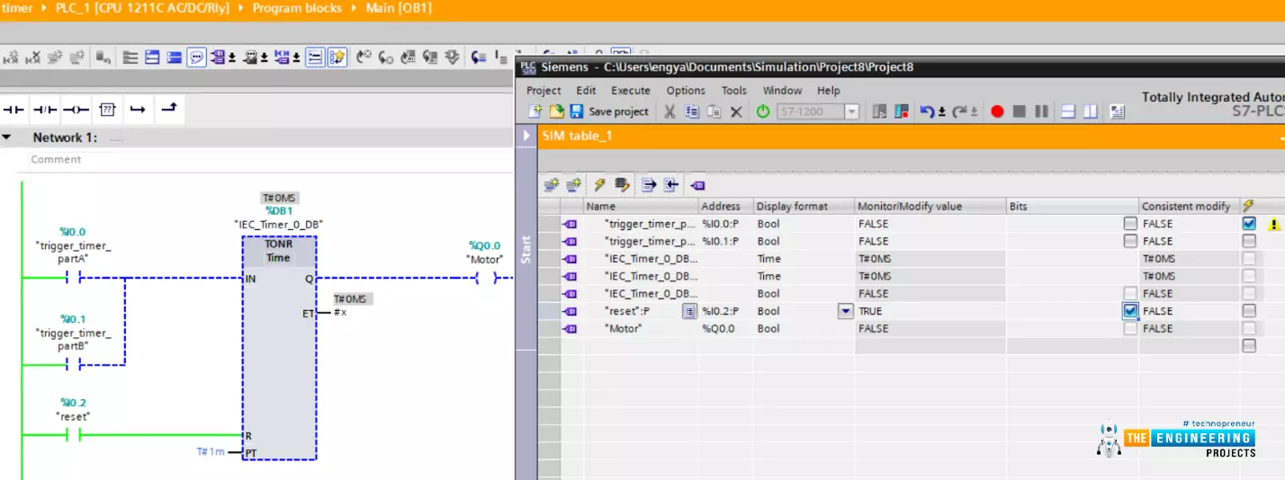
Hello friends! I hope you are doing very well, today we have a very crucial topic which is “timers”. Yes! Exactly like what comes to your mind. For running equipment i.e. motor at a specific time and/or for some amount of time we need timers. Timers are used even before PLC in classic or relay logic conventional control. However, there is a big difference between capabilities and limitations between using physical timers in classic or old fashion relay logic and using software timers in PLC. By completing this article you will be able to know what are timers and their types and applications. In addition, we are going to show off how to use timers in ladder logic programming with examples.
What are timers used for in industrial applications?
Well! ...
Hello friends, all of us know that PLCs are nothing but the smartest migration from relay logic control to programmable logic control. Also, you know clearly that, logic is the heart of any programming language, and the same is applied to ladder logic programming. Bitwise operators represent the logical operations including the basic logical operations like AND, OR, and NOT and the derived logical operations like NAND, NOR, and XOR. in most cases, for each bitwise operator, there are inputs based on which the output can be decided. Some of these bitwise operators have two inputs and some have only one input. In this article, we are going to present how we can use these bitwise logical operators and their instructions with examples and practice using the PLC simulator.
Logic Gates ba ...
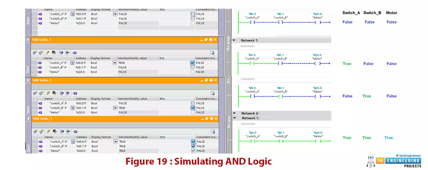
Hello friends, I hope you all are doing great. In today's tutorial, we are going to design logic gates in PLC Simulator. It's our 4th tutorial in Ladder Logic Programming Series. We come today to elaborate the logic gates with comprehensive details for their importance in PLC programming. you can consider logic gates as the building blocks of ladder logic programming. Like every time we start with telling what you guys are going to have after completing this session? For those who like to buy their time and calculate for feasibility, I’d like to say by completing this article, you are going to know everything about what types of logic gates, how they are designed and how they work, how you can translate the logic in your head into the logic gate a ...
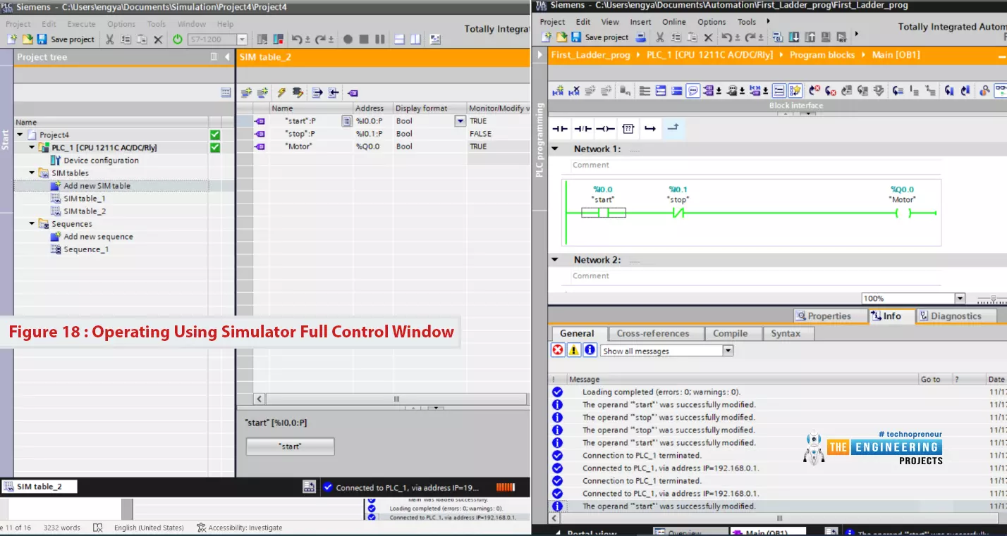
Hello friends, I hope you all are doing great. In today's tutorial, I am going to create the first Ladder Logic Program in PLC Simulator. It's 3rd tutorial in our Ladder Logic Programming Series. In our previous tutorial, we have installed PLC Simulator and now we can say our lab is ready to learn and practice. So let us get to work and get familiar with the ladder logic components.
After this article, you will have a complete understanding of PLC contact and coil including their types and possible causes. Because they are the building block of any rung of a ladder logic program. So let us start with ladder logic rung components.
Ladder Logic Contact/Input
In ladder logic programming, a contact represents the input of the system and it could b ...
Hi friends and hope you are doing very well. Today we would like to take one tutorial which is very essential in the industry which is analog input processing for handling analog measurements of physical signals like temperature, humidity, pressure, distance, flow and level of liquids, etc. Typically, sensors produce two types of analog signals to represent the equivalent measured signal which is current and voltage signals. The currently produced signals would be within the range of 4-20 mAwhile voltage signals are in the range of 0-10 v. because, that output signals represent physical signals, the limits of output signals are 0 to 10 v for voltage based sensors and 4 to 20 mA for current-based sensors, these values should be scaled to represent ...
Hello everyone, I hope you all are doing great. In today's tutorial, I am going to share the detailed fIn the previous post, we have seen Introduction to PLC, which was quite simple and has the basic introduction to PLC. To day we are gonna have a look at Getting Started With Ladder Logic For PLC. Ladder Logic, also named as Ladder Logic Programming, is the programming language for PLCs. Its normally considered as the most difficult language among the engineers because of its complex structure, but if you ask me then I will say its the most interesting programming language.
Ladder Logic is different from the usual programming language of Microcontrollers like Arduino, PIC Microcontroller etc. Microcontrollers programming usually compiled from top ...
Hi friends, I hope you are very well; today in this tutorial, we will practice conditional jumping for performing some code at the occurrence of some conditions. Like any other programming language, jumping is one of the most common approaches to transfer the execution from its sequential mode to run different processes or instructions marked by a label and bypassing the lines of codes in between the last executed transaction before the jump instruction and the labeled instruction whom the program is going to move to. The good thing about this technique is shortening the scan cycle of the program due to not running the whole program. However, using jumping techniques in coding is very dangerous. It would help if you were careful of missing some op ...
Hi, my friends. Welcome to share a new tutorial in our ladder logic programming series. Today we will discuss counters in ladder logic programming using an expert’s view. So let’s wear the glasses of an expert in ladder logic programming and look deeply into counters, the types of counters, their variables and bits. In addition, techniques of using counters to solve a different kinds of problems that need counting. And without questions like every time, we will enjoy practicing programming and simulating all about counters. So with no further delay, let’s jump into our tutorial and nail that counters.
Counters in real life
Tell me, guys, if you can imagine an industrial project or machine that does not need to count parts, products, or processing cycles. Actually, in most cases in indust ...
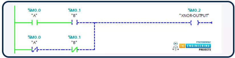
Hello friends! I hope you are all very well! I am so happy to meet you today to continue learning and practicing PLC ladder logic programming. In an earlier part, we already have gone through the very basic logic gates of “AND”. “OR”, and “NOT”. Today we are going to resume the simulation of logic gates. We have started and gone through simulating the basic logic gates which are “AND”, “OR”, and “NOT” as they are the most important basic logic gates by which we can form other logic gates. However, because the logic of large-scale projects is getting more and more complicating, a lot of time we have to use the other functions to do tasks faster. For example, we have shown in the logic gates article that, XOR can be used to compare two inputs and ch ...