Hello friends! In the previous ladder-logic introduction , we built AND, OR and NOT conditions using contacts and coils. Today we will combine those building blocks to create NAND, NOR, XOR and XNOR. Each gate answers a different question about its inputs, so understanding the question is more useful than memorizing a diagram. We will retain the original X0, X1 and Y0 examples and walk through their truth tables. Then we will apply the same reasoning to a sensor-disagreement indicator and a command-feedback comparison. These examples make it easier to see why a rung that is logically correct can still be unsuitable for a particular process requirement. Before starting, remember that ladder contacts inspect Boolean data. They do not change the physical input or carry a real voltage through ...
Hello friends! In our Introduction to PLC , we looked at the controller, its terminals and the difference between a program command and an electrical output. Today we will connect those ideas using ladder logic. We will start with one input and one output, then build AND, OR and NOT conditions before adding a simple memory circuit. Ladder diagrams look like relay circuits, which makes them approachable once you understand what their symbols mean. However, the diagram is a program. A contact symbol tests a stored Boolean value; it is not a physical switch carrying voltage through the screen. Keeping that distinction clear will prevent many common wiring and programming mistakes. The retained examples use X addresses for inputs and Y addresses for outputs, following the style of the original ...
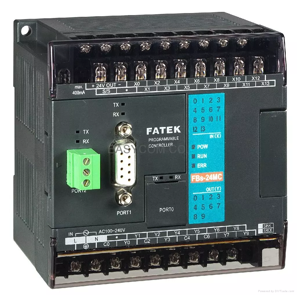
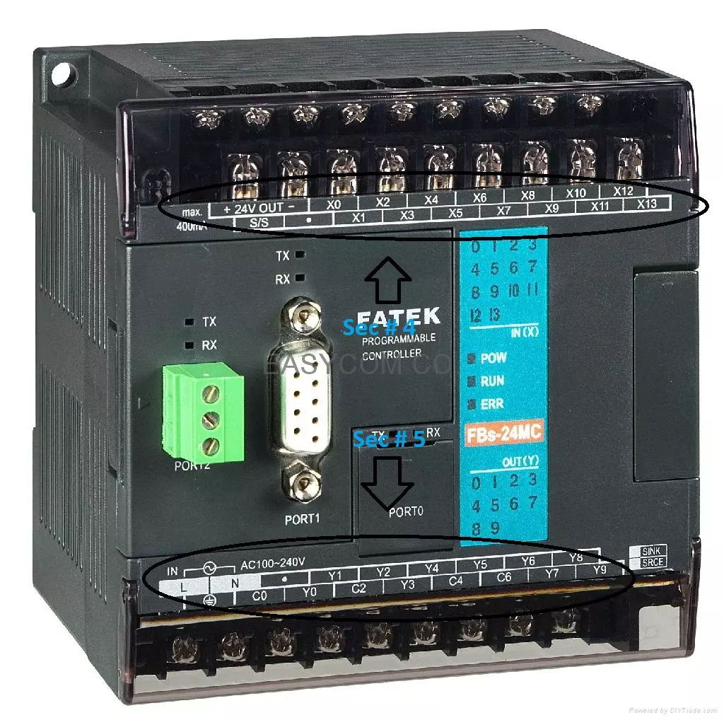
Hello friends! Today we will begin our PLC series with the hardware and operating principles of a programmable logic controller. My original introduction grew out of an automated coffee-mixing project. That is a useful example because it involves several familiar tasks: reading switches, checking conditions, opening valves and controlling how long a process runs. Before drawing a ladder program, we need to understand what happens between a sensor and an actuator. A correct program cannot repair an incorrectly wired input, an unsuitable output or a missing power supply. We will therefore work from the controller's main sections through its scan cycle, input and output connections, and a small process example. The original project identified its controller as a FATEK FBs-20MA. We will retain ...