Hello friends! If you are developing an embedded project and need help with its firmware, The Engineering Projects can discuss your microcontroller programming requirements with you. Your project may involve a new prototype, a circuit that is not responding correctly or an existing program that needs a clearly defined improvement. Useful programming work starts with understanding the hardware and the required behaviour. A sentence such as “control a motor with a sensor” describes an idea, but it does not yet define a complete system. We need to know which motor, which sensor, how quickly the controller must respond and what should happen when a signal disappears. This page explains the types of work you can discuss with us, the information to prepare and the deliverables to agree before de ...
Hello friends! Today we will control a servo motor with the PIC16F877A and observe its movement in Proteus ISIS. We will begin with the three servo connections, understand the command waveform, and then write a small program that selects positions using two pushbuttons. In the previous tutorials, we explored DC motor direction control and stepper motor sequencing . A positional hobby servo is different because the motor, gearbox, position sensor, and controller are already assembled together. Our PIC requests a position rather than switching the motor windings itself. We will keep the original PIC and button arrangement, but use a repeated control pulse with a sensible frame period. Along the way, we will separate what the simulated angle display tells us from what a physical servo must be ...
Hello friends! In the previous tutorial, we controlled the direction of a DC motor in Proteus . Now we will work with a stepper motor, where rotation depends on applying an ordered sequence to the windings. We will begin with the original six-wire simulation, inspect the sequence manually, and then explain how a microcontroller and driver can generate it. The original screenshots use Logic State sources to make individual winding states visible. They are useful for understanding the sequence, but they are not a physical driver circuit. We will preserve the images and add the missing distinction between simulated logic sources, microcontroller outputs, and the winding-current path. By the end, you should understand unipolar and bipolar wiring, wave drive and half stepping, direction reversa ...
Hello friends! In this guide, we will learn how to use Proteus ISIS and ARES, starting with a simple circuit and gradually moving toward microcontroller simulations and PCB design. I have kept the original tutorial collection so that you can follow a lesson in detail whenever you reach that stage. Our goal is to understand the complete development process. We will draw a circuit, calculate what it should do, simulate its behavior, examine signals with instruments and then prepare a physical board layout. Each stage answers a different question, so a successful simulation is one step in the process rather than the final proof of a finished product. If you are new to Proteus, follow the sections in order. If you already use it, choose the topic you need from the linked lessons. Some screensh ...
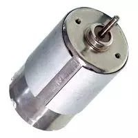
Hello everyone, I hope you are doing well. In this tutorial, we will compare DC and AC motors from their operating principles to their speed control, maintenance and applications. Both convert electrical energy into mechanical energy through electromagnetic force, but those broad labels contain several different motor families. The first important correction is that an AC motor is not simply a DC motor with continuous slip rings. Most industrial AC motors create a rotating stator field and use either induction or synchronous interaction to produce rotor torque. We will therefore compare common brushed DC motors, brushless DC motors, induction motors and synchronous AC motors. Figure: A small DC motor introduces the comparison of DC and AC motor operation. DC and AC Motor Comparison Feature ...