


Project Files of nRF24L01 Library for Proteus V1.1 (2.4 GHz RF + Arduino)
 Libraries
 Code
 Projects
 Simulation
nrf24l01-tep-v1-1-367f6cce25d540b2a9320bcf77ac087b.zip

nRF24L01 Library for Proteus V1.1
nRF24L01 Library for Proteus V1.1 comes as a ZIP archive of 121 files (1.6 MB, 3.7 MB unpacked) holding Proteus library files, simulation model DLLs, a Proteus simulation, an Arduino sketch, an Arduino library, compiled HEX firmware, source code and data files.
- LIBProteus library
- IDXProteus library index
- DLLProteus model
- DSNProteus simulation
- INOArduino sketch
- LIBArduino library
- HEXHEX firmware
- SRCSource code
- CSVData file
Description
nRF24L01 Library for Proteus V1.1 is the download package that goes with our tutorial nRF24L01 Library for Proteus V1.1 (2.4 GHz RF + Arduino). On this page you can download the ZIP file (1.6 MB) and see what is inside before you save it: 121 files in 41 folders, the Proteus library files (LIB and IDX), the simulation model (DLL), a ready Proteus simulation, an Arduino sketch, an Arduino library, the compiled HEX firmware, the source code and data files. The tutorial explains the design; this page gets the files onto your computer and into use.
What this library is
NRF24L01-RF-Library-for-Proteus-v1.1.zip with nRF24L01 Simple and Advance (TEPNRF24L01.LIB and TEPNRF24L01.DLL), the TEP Serial Monitor and Arduino UNO libraries for Proteus, the two-UNO wireless simulation with its HEX files, the transmitter and receiver sketches with the RF24 library and a README.
This is version 1.1; older or newer releases, when they exist, are listed in the Development tab.
What is inside the ZIP file
- ArduinoV3TEP.LIB – Proteus library, 95.6 KB
- TEPNRF24L01.LIB – Proteus library, 89.9 KB
- TEPSERIALMON.LIB – Proteus library, 11.1 KB
- ArduinoV3TEP.IDX – Library index, 830 B
- TEPNRF24L01.DLL – Simulation model, 344.5 KB
- TEPSERIALMON.DLL – Simulation model, 978 KB
- and 115 more, all listed in the File Structure tab
The archive unpacks to 3.7 MB and carries its own README (README.txt), shown in the README tab above.
How to download
Use the download panel at the top of this page: after the counter (30 seconds for guests, 10 for members) the black button unlocks and the ZIP file comes straight from our content network. If the browser opens it instead of saving, use Save as; extract the whole archive before using anything inside it.
How to install
- Step 1: Extract the ZIP file with Windows (Extract All), 7-Zip or WinRAR, keeping its folders.
- Step 2: Close Proteus and copy ArduinoV3TEP.LIB, TEPNRF24L01.LIB and TEPSERIALMON.LIB and ArduinoV3TEP.IDX into its LIBRARY folder (Proteus 8: C:\Program Files (x86)\Labcenter Electronics\Proteus 8 Professional\LIBRARY).
- Step 3: Copy TEPNRF24L01.DLL and TEPSERIALMON.DLL into the MODELS folder next to it, so the part simulates.
- Step 4: Start Proteus, press P and search for "ArduinoV3TEP"; place and wire it as in the tutorial.
- Step 5: In the Arduino IDE use Sketch → Include Library → Add .ZIP Library, then restart the IDE.
- Step 6: Open NRF24_Receiver.ino, NRF24_Transmitter.ino and AcknowledgementPayloads.ino and 19 more in the Arduino IDE, pick board and port and Verify (Export Compiled Binary gives the HEX).
- Step 7: Build print_details.py with the compiler the tutorial names.
- Step 8: In Proteus set the controller's Program File to NRF24_Receiver.hex and NRF24_Transmitter.hex; on hardware, flash the same file.
- Step 9: Open NRF24L01-ArduinoUnoV3.pdsprj in Proteus and press Play.
Read the detailed guide
This page is for the files. The full tutorial, nRF24L01 Library for Proteus V1.1 (2.4 GHz RF + Arduino), explains the circuit and the code step by step and shows the working results and the simulation; read it before you build. Questions about the download or the installation go in the comments below; more Proteus downloads are listed further down this page.

File Structure
 File Structure
7.7 KB3.7 KB6.6 KB5.2 KB13.6 KB8.4 KB7.2 KB7 KB6 KB5.9 KB6.2 KB7.2 KB5.3 KB2.4 KB1.5 KB5.4 KB227 B8.1 KB8.3 KB6.5 KB7.2 KB11.6 KB6.2 KB4.2 KB994 B1.1 KB536 B730 B601 B1.2 KB1.8 KB351 B2 KB1020 B1.2 KB354 B1010 B721 B415 B2.3 KB807 B204 B1.8 KB990 B1.6 KB2 KB1.5 KB1 KB388 B458 B1 KB211 B462 B606 B2 KB594 B1.2 KB536 B325 B582 B1.7 KB1019 B2.2 KB68.6 KB104.3 KB326 B240 B255 B3.1 KB1.4 KB1.5 KB1.2 KB1.8 KB1.1 KB519 B4.8 KB2.6 KB209 B5.7 KB1.4 KB1.9 KB4.1 KB965 B588 B564 B1.2 KB482 B2 KB1.4 KB245 B294 B1.3 KB1.8 KB841 B5.2 KB146.5 KB10.6 KB2 KB1.1 KB407 B17.6 KB4.4 KB1.2 KB1.2 KB72.2 KB100.2 KB9 KB7.8 KB9.2 KB830 B95.6 KB89.9 KB11.1 KB344.5 KB978 KB23.5 KB27.7 KB34.2 KB344.5 KB978 KB27 KBGallery12 images from the tutorialOpen the tutorial
 Gallery12 images from the tutorial
The circuit, the board and the results as they appear in nRF24L01 Library for Proteus V1.1 (2.4 GHz RF + Arduino). Open an image for its full size.
README
 README
nRF24L01 2.4 GHz RF TRANSCEIVER MODULE (Nordic nRF24L01+, PCB antenna) LIBRARY FOR PROTEUS - V1.1
Designed by The Engineering Projects
www.TheEngineeringProjects.com

IMPORTANT LINKS
Article (read it first - pictures, step by step, every feature explained):
  https://www.theengineeringprojects.com/2026/09/nrf24l01-proteus-library.html
Report a bug or suggest a feature (our forum):
  https://www.theengineeringprojects.com/forum/category/nrf24l01-proteus-library
The demo uses our TEP Serial Monitor Advance (included) instead of Proteus's
Virtual Terminal - its own article:
  https://www.theengineeringprojects.com/2026/10/serial-monitor-advance-proteus-library.html
Support us (the libraries are free):
  https://www.theengineeringprojects.com/donate

FILE STRUCTURE
NRF24L01-TEP-v1.1/
|-- Proteus Library Files/
|   |-- ArduinoV3TEP.IDX                              0.8 KB   its index -> LIBRARY folder
|   |-- ArduinoV3TEP.LIB                             95.6 KB   TEP Arduino UNO (demo) -> LIBRARY folder
|   |-- TEPNRF24L01.LIB                              89.9 KB   nRF24L01 Simple + Advance (2 devices) -> LIBRARY folder
|   |-- TEPSERIALMON.LIB                             11.1 KB   TEP Serial Monitor Advance -> LIBRARY folder
|-- Proteus Model Files/
|   |-- TEPNRF24L01.DLL                             344.5 KB   nRF24 model (shared with the nRF24L01+PA+LNA library) -> MODELS
|   |-- TEPSERIALMON.DLL                            978.0 KB   Serial Monitor model -> MODELS folder
|-- Proteus Simulation/
|   |-- NRF24_Receiver.hex                           27.7 KB   UNO 2 (receiver v1.1)
|   |-- NRF24_Transmitter.hex                        34.2 KB   UNO 1 (transmitter v1.1)
|   |-- NRF24L01-ArduinoUnoV3.pdsprj                 23.5 KB   demo: UNO 1 + nRF24L01 Simple, UNO 2 + Advance
|   |-- TEPNRF24L01.DLL                             344.5 KB   copy of the model so the demo runs as is
|   |-- TEPSERIALMON.DLL                            978.0 KB   copy of the monitor model
|-- Arduino Code/
|   |-- NRF24_Receiver/NRF24_Receiver.ino             7.8 KB   sketch (source of the .hex)
|   |-- NRF24_Transmitter/NRF24_Transmitter.ino       9.2 KB   sketch (source of the .hex)
|   |-- libraries/RF24/                             778.8 KB   RF24 1.6.2 (GPL-2.0, LICENSE), 107 files
|-- README.txt                                      ~27.9 KB   this file
Total: 3.66 MB (unzipped). The C++ source code of the model is not included.

WHAT IS IT?
A simulation model of the popular nRF24L01+ 2.4 GHz radio module (the small black
board with the zig-zag PCB antenna and the 2 x 4 header) for Proteus 8. Your Arduino talks to it over
SPI exactly like to the real chip: every register, every SPI command, the 3-level
TX and RX FIFOs, Enhanced ShockBurst with auto-ACK and retransmissions, dynamic
payloads, ACK payloads, six RX pipes, the IRQ pin and the timing (130 us settling,
the bits on the air at 250 kbps / 1 Mbps / 2 Mbps, 1.5 ms power-up). It runs the
unmodified RF24 library. Every TEP nRF24L01 in a design shares one simulated
2.4 GHz air: radios on the same channel, data rate, CRC and address talk to each
other when the link budget allows - you choose the DISTANCE between the radios
(1 m ... 2 km) and the model works out the received level (your PA level, the
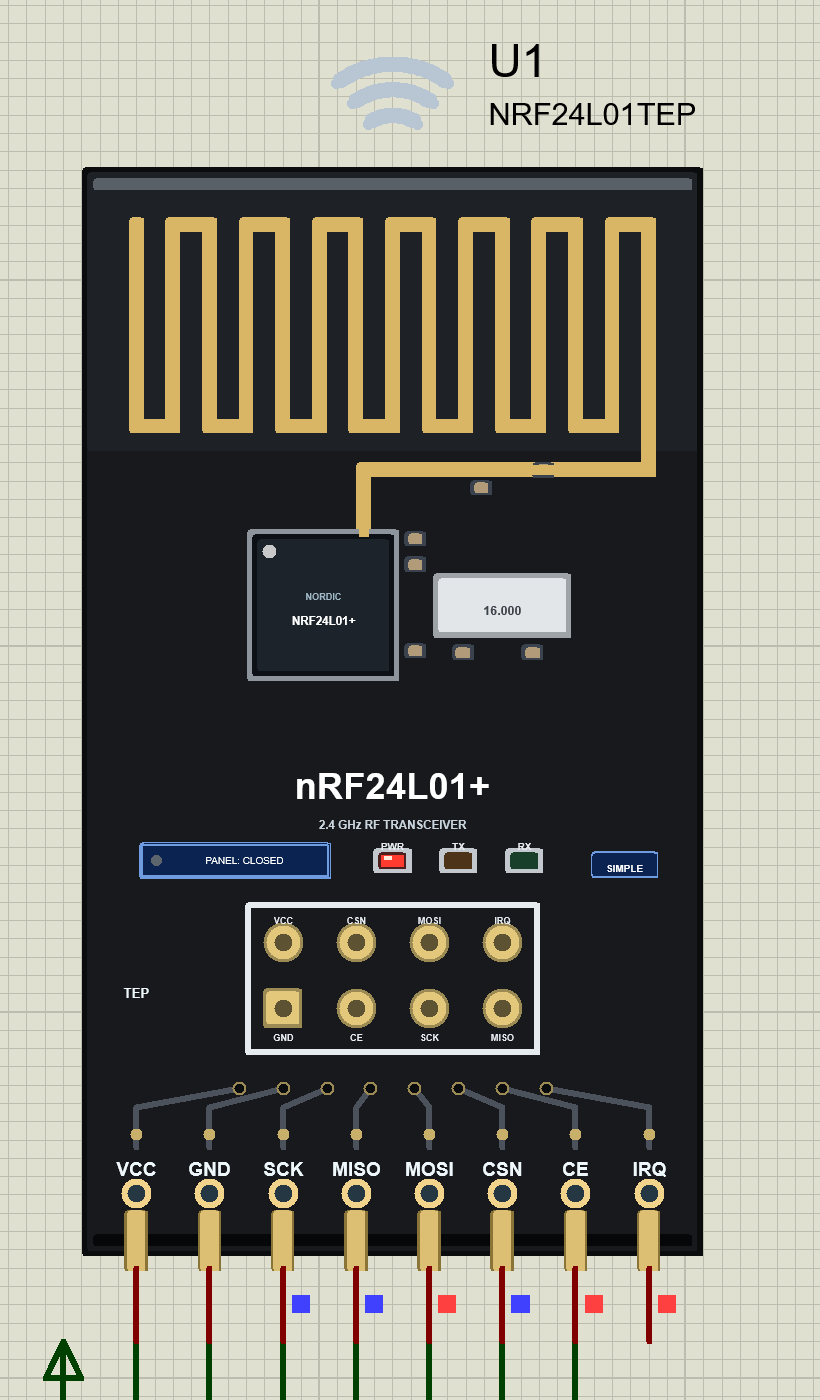
path loss, the receiver's sensitivity at its data rate). The part looks like the
real module: a tall black board with the zig-zag PCB antenna on its top end, the
nRF24L01+ chip and its 16 MHz crystal in the middle and the 2 x 4 header (pins
labelled) on its bottom end. While the simulation runs its PCB antenna glows
orange while it transmits and green while it receives, radio waves above it
ripple out (sending) or in (receiving), and three LEDs show what happens: PWR
(red, lit while VCC is there), TX (orange, blinks for every packet sent) and RX
(green, blinks for every packet or ACK received). The LEDs are a TEP addition -
the real module has no LEDs.

TWO DEVICES IN ONE LIBRARY (search "nRF24L01" in Pick Devices):
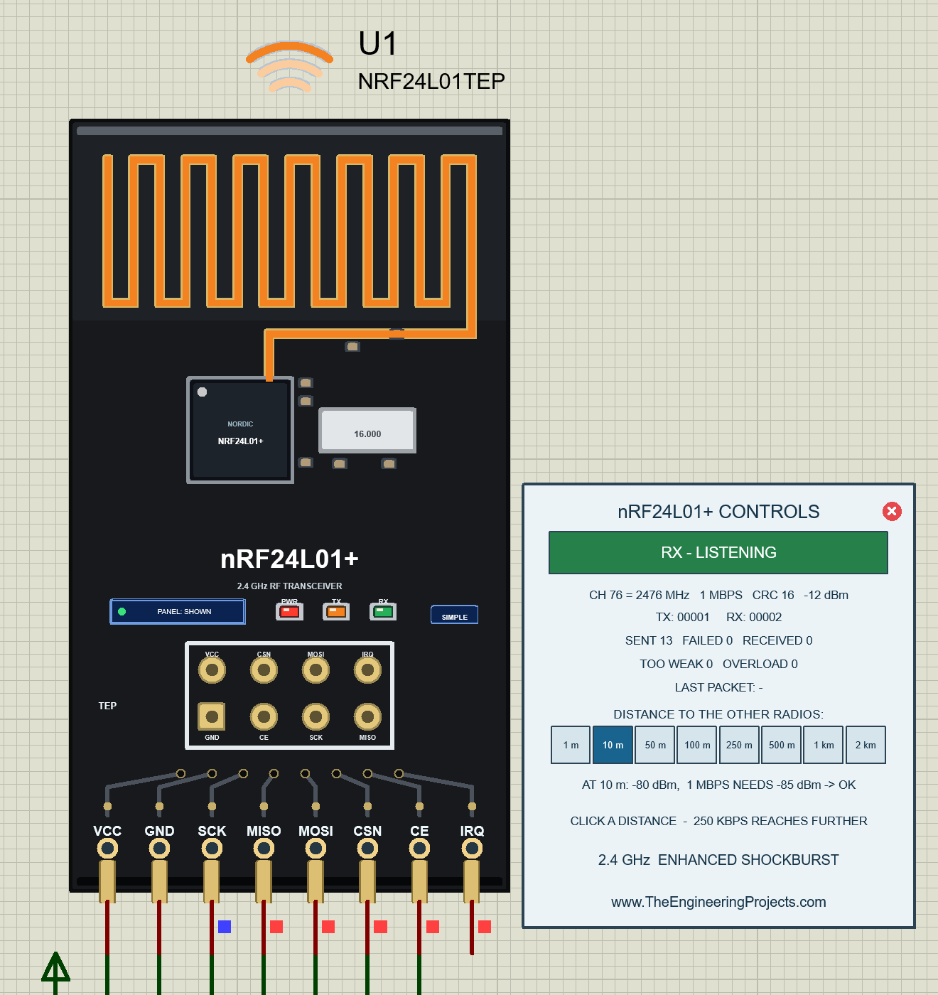
  nRF24L01 Simple    device NRF24L01TEP     "nRF24L01 RF Transceiver Module - Simple"
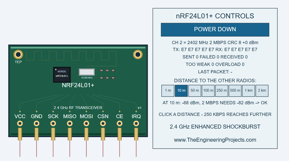
                     On-Sheet Panel: the control panel is drawn on the
                     schematic next to the module (the v1.0 panel): mode,
                     channel / frequency, data rate, CRC, TX power, the TX and RX
                     addresses, SENT / FAILED / RECEIVED, TOO WEAK / OVERLOAD, the
                     last packet with its level, the DISTANCE buttons and the
                     predicted link budget. The red X in the panel header closes
                     it, the PANEL button on the board opens it again. Your v1.0
                     designs keep working with this device.
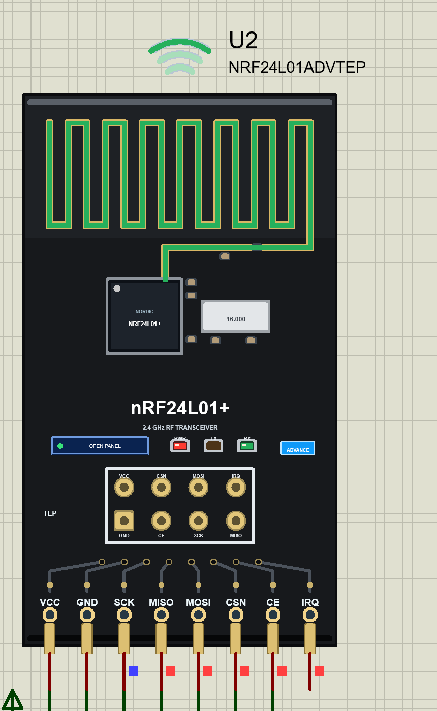
  nRF24L01 Advance   device NRF24L01ADVTEP  "nRF24L01 RF Transceiver Module - Advance"
                     Pop-Up Panel: only the module board on the schematic; at Run
                     a TEP pop-up window opens - the same look as the TEP Serial
                     Monitor (move it by its header, resize it, minimise it). The
                     tabs Radio and Test sit in the header; the gear and ? icons
                     open Settings and Help; the palette icon switches the theme:
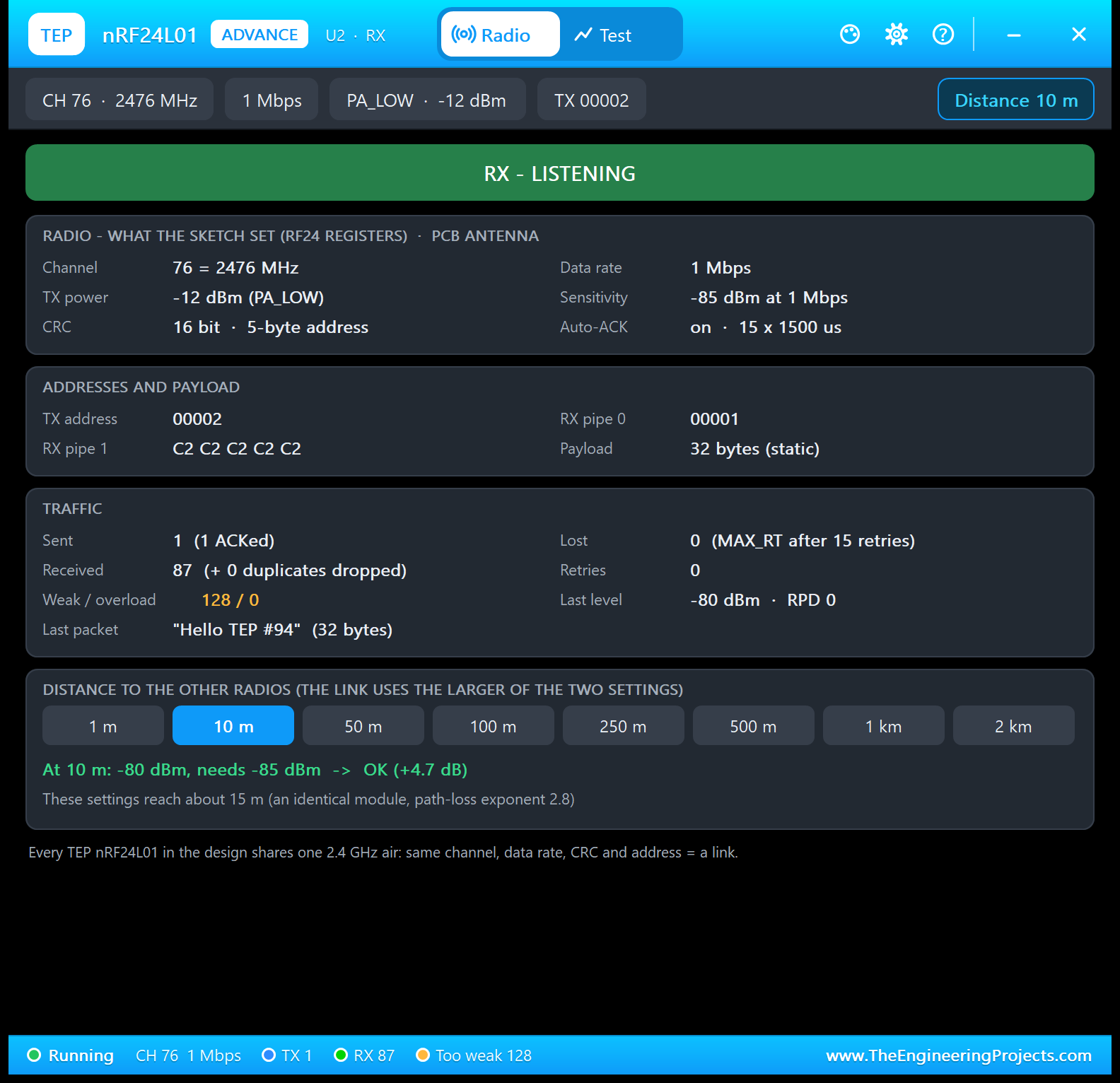
                       Radio     the state banner, RADIO (channel, data rate, TX
                                 power, sensitivity, CRC, address width, auto-ACK
                                 and retries - what your sketch wrote), ADDRESSES
                                 AND PAYLOAD, TRAFFIC (sent / ACKed / lost, received,
                                 duplicates, retries, too weak / overload, the last
                                 level and RPD, the last packet) and DISTANCE (the
                                 eight buttons, the level at that distance and how
                                 far these settings reach)
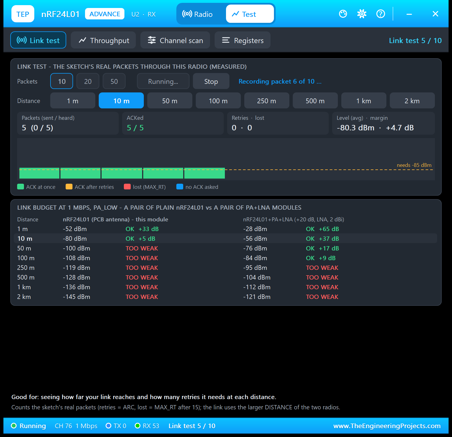
                       Test      four test tools, all measured on the model: Link
                                 test, Throughput, Channel scan, Registers (see THE
                                 TEST TOOLS below)
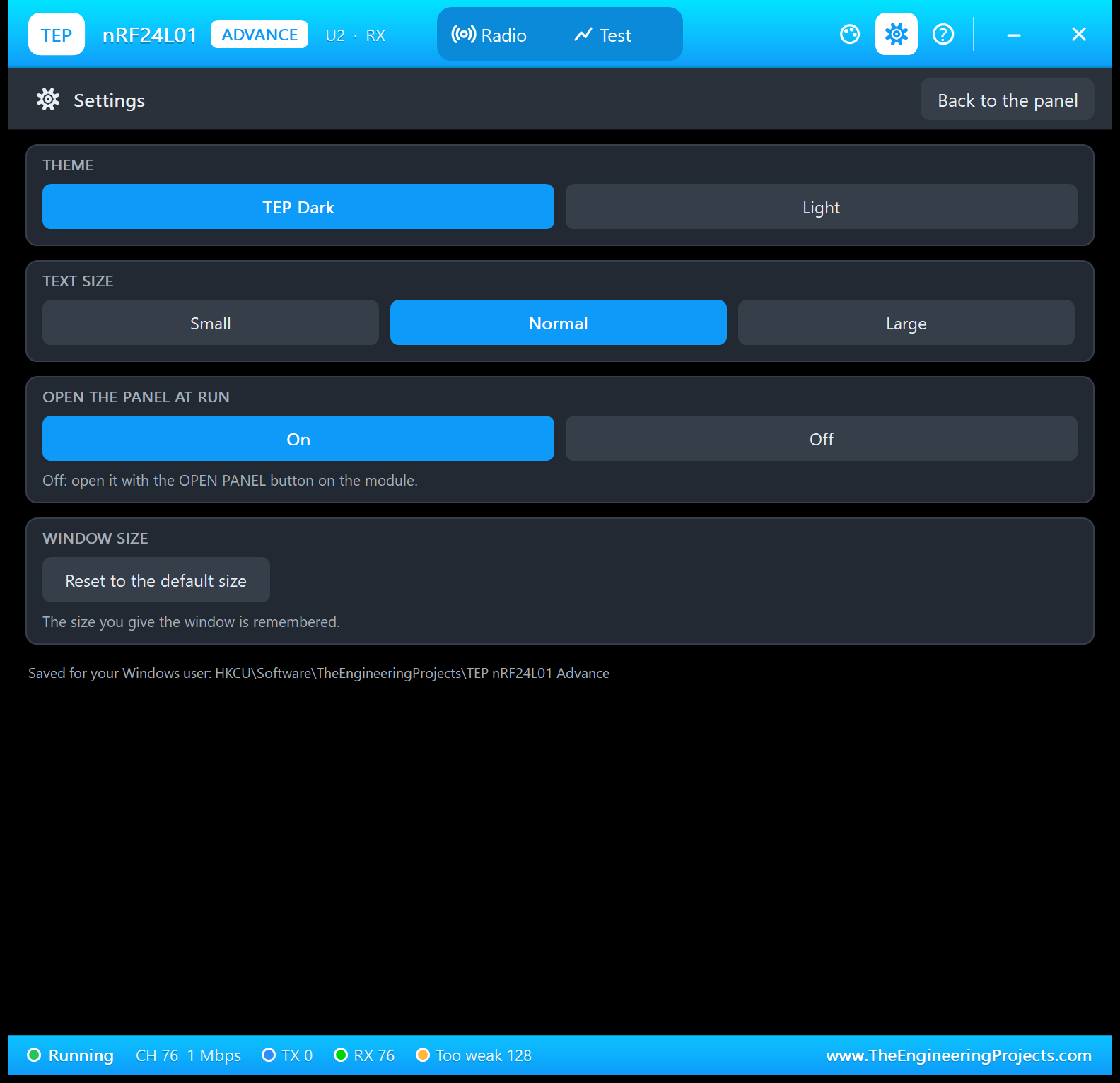
                       Settings  theme (TEP Dark / Light), text size, open at Run,
                                 window size - remembered for your Windows user
                       Help      Help & Support like the TEP Serial Monitor: report
                                 a bug, suggest a feature, article, user guide,
                                 updates, donate, website, forum; Copy diagnostics
                                 (radio, registers, traffic, test results, the other
                                 radios) for a bug report
                     The OPEN PANEL button on the board opens the window again
                     after you close it.
Both devices use the same model (TEPNRF24L01.DLL). This DLL is also the model of
our nRF24L01+PA+LNA library (shared with the nRF24L01+PA+LNA library - identical
TEPNRF24L01.DLL in both packages, so installing both is safe), and plain and PA+LNA
modules in one design talk to each other.

NEW IN V1.1
* Two devices: nRF24L01 Simple (the panel on the sheet, close / open) and
  nRF24L01 Advance (pop-up window with the radio page, four test tools, settings
  and help) - see above.
* Board: redrawn like the real module - BLACK, tall and narrow, the zig-zag PCB
  antenna on the top end, the nRF24L01+ chip, the 16.000 MHz crystal, the 2 x 4
  header with its pin names on the bottom end (v1.0: a wide green board). The 8
  Proteus pins stay where v1.0 had them, so the wiring of a v1.0 design fits.
  The PCB antenna glows orange while the module sends and green while it
  receives, radio waves above it; new LEDs PWR / TX / RX (a TEP addition - the
  real module has none): PWR lights with VCC, TX blinks for every packet sent, RX
  for every packet or ACK received (each blink held 0.3 / 0.4 s so you see it);
  a PANEL / OPEN PANEL button and a SIMPLE / ADVANCE badge beside the LEDs.
* Model: every transmission (packet and ACK) now reaches the Received Power
  Detector of every radio listening on that channel, whatever its address or data
  rate (like the real RPD - the RF24 scanner example works); the model records
  what the test tools show (packets with their retries and levels, the SPI
  commands, the channel activity). The DISTANCE buttons, the link budget and
  everything of v1.0 are unchanged.
* The demo uses the TEP Serial Monitor Advance instead of Virtual Terminals - one
  monitor per Arduino (U3 = UNO 1, U4 = UNO 2) with quick buttons - and shows both
  styles: UNO 1 with nRF24L01 Simple, UNO 2 with nRF24L01 Advance.
* The demo sketches (v1.1) keep every v1.0 output line and add Serial Monitor
  commands (SEND, PING, STATUS, CH, RATE, PA, AUTO, HELP) and a link line every
  10 s; the transmitter now listens between its packets, so the receiver can send
  to it too (and answer PING with PONG).
* Version 1.1 everywhere; the C++ source code of the model is no longer included.

TEST STATUS
v1.0 was tested in Proteus 8.5 SP0 (29 Sep 2026) with the v1.0 demo: the
transmitter's packets arrived at the receiver ("Sent: Hello TEP #n -> ACK
received" / "Received #n: Hello TEP #n"), cutting the link made every packet
fail after 15 retries and restoring it worked at once; with the model of 30 Sep
the plain v1.0 demo also ran unchanged with the DISTANCE panel (10 m).
v1.1 was tested in Proteus 8.5 SP0 (6 Oct 2026) with this package's demo: both
Serial Monitors and the Advance pop-up open at Run (no system caption row); the
black boards light PWR and blink TX / RX with every packet and ACK, the PCB
antenna glows orange / green. U1 (Simple): 10 m OK (-80 dBm), 100 m TOO WEAK
(-108 dBm, sends fail), back to 10 m, the red X and PANEL; PING -> PONG from
node 2 after 2.1 ms, STATUS. U2 (Advance): Radio page, Test > Link test 5 / 5
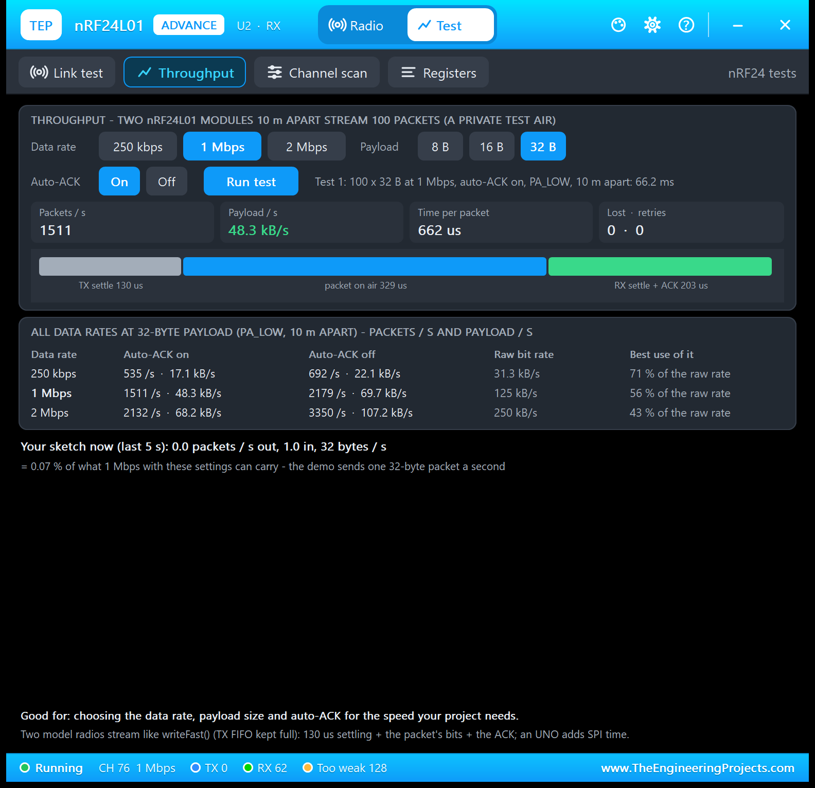
ACKed at -80.3 dBm (+4.7 dB), Throughput 1511 packets/s at 1 Mbps (48.3 kB/s,
662 us per packet), Channel scan (U1 on channel 76), Registers (U1 = PARTNER),
Settings, Help, close and OPEN PANEL.
PC tests:
PC tests: 1417 automatic checks on a PC: 69 with the UNMODIFIED RF24 library
driving two chip models bit by bit over SPI (the v1.0 tests, unchanged); 54 on the
v1.1 chip features (RPD from every carrier, the packet records, the SPI log, the
channel scan, the partner check, the throughput bench); 145 on the complete Proteus
model (the 38 of v1.0 unchanged + both devices of both libraries, the red X and
PANEL, OPEN PANEL, a v1.0 design, the antenna glow, the PWR / TX / RX LEDs, the
pop-up window without a caption row, its pages, the four tools with measured
numbers, Help links, diagnostics); 57 with the four REAL v1.1 demo sketches
running on two simulated UNOs at once (every v1.0 line, the commands, PING both
ways, CH / RATE / PA / AUTO, the link line); 1092 on the rendered pop-up windows
and boards (every page fits in TEP Dark and Light, at Large text and 150 % DPI;
every tool's hint lines fit; the header line fits beside the tabs in every
state; the LEDs lit / dark on the boards as they should be).

INSTALLATION (about 2 minutes)
1. Close Proteus. Extract the WHOLE ZIP to a normal folder (e.g. Desktop).
2. Copy everything in "Proteus Library Files" (TEPNRF24L01.LIB with both devices,
   TEPSERIALMON.LIB and the TEP Arduino UNO V3 library ArduinoV3TEP.LIB / .IDX
   used by the demo) to the LIBRARY folder of Proteus, for example:
     C:\Program Files (x86)\Labcenter Electronics\Proteus 8 Professional\LIBRARY
   (on some PCs: C:\ProgramData\Labcenter Electronics\Proteus 8 Professional\
   LIBRARY - use the folder that already holds Proteus's own .LIB files).
3. Copy TEPNRF24L01.DLL and TEPSERIALMON.DLL from "Proteus Model Files" to the
   MODELS folder (...\Proteus 8 Professional\MODELS).
4. Updating from v1.0: replace TEPNRF24L01.LIB (delete any TEPNRF24L01.IDX) and
   TEPNRF24L01.DLL. A v1.0 design keeps its v1.0 symbol: it runs with the new
   model (the v1.0 panel and its DISTANCE buttons, without the v1.1 board parts and
   the red X) - re-pick the part to get the v1.1 symbol. If you also use our
   nRF24L01+PA+LNA library, its TEPNRF24L01.DLL is the same file.
5. Start Proteus. In Pick Devices (P) search "nRF24L01": you get the Simple and
   the Advance device (category Peripherals > Wireless).

RUN THE DEMO
"Proteus Simulation\NRF24L01-ArduinoUnoV3.pdsprj" - keep the two .hex files and
the two DLLs beside the project.
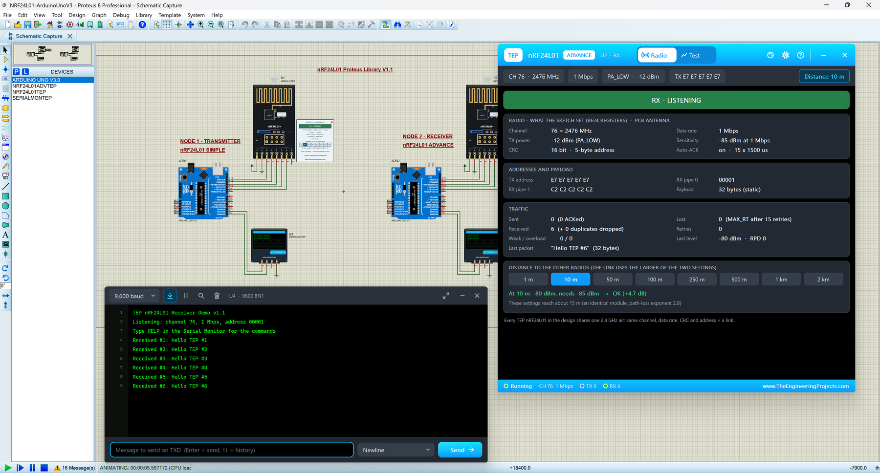
  UNO 1 (ARD1): NRF24_Transmitter.hex, nRF24L01 Simple (U1) and Serial Monitor U3.
  UNO 2 (ARD2): NRF24_Receiver.hex, nRF24L01 Advance (U2) and Serial Monitor U4.
  1. Press Run. Both monitor windows open (9600 baud) and so does U2's pop-up.
     U3 shows "Sent: Hello TEP #1  -> ACK received" every second, U4 "Received
     #1: Hello TEP #1"; U1's panel counts SENT, U2's pop-up RECEIVED; the PCB
     antennas flash orange (U1 sending) and green (U2 receiving), U1's TX and RX
     LEDs blink (its packet, the ACK back), U2's RX LED blinks. U1's panel shows
     RX - LISTENING between its packets: the v1.1 transmitter listens for node 2's
     messages (PING, SEND) between sends (v1.0 sat in STANDBY-I).
  2. U3 / U4 quick buttons: PING (the other node answers PONG - the round trip,
     about 1.5 ms), STATUS, SEND Hello from node 1 / 2 (the other monitor prints
     it), HELP. Type your own: SEND <text>, CH 90 (then on the other monitor too),
     RATE 250K (both), PA MAX, AUTO OFF / ON (UNO 1).
  3. Click 100 m on U1's panel (or on U2's Radio page): every packet now fails
     ("FAILED, no ACK" after 15 retries; -108 dBm, 1 Mbps needs -85 dBm). Back to
     10 m and it works again. Try 250 kbps (RATE 250K on both) and PA MAX: the link
     reaches about 80 m. Close U1's panel with its red X, open it with PANEL.
  4. U2 (Advance): open the Test tab:
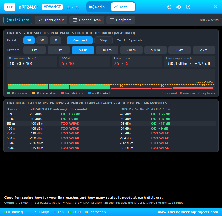
       Link test: 10 packets, Run test - U1's next 10 packets with their level and
         retries; click 100 m during the test and watch the bars turn red.
       Throughput: 250 kbps / 1 Mbps / 2 Mbps, payload, auto-ACK, Run test.
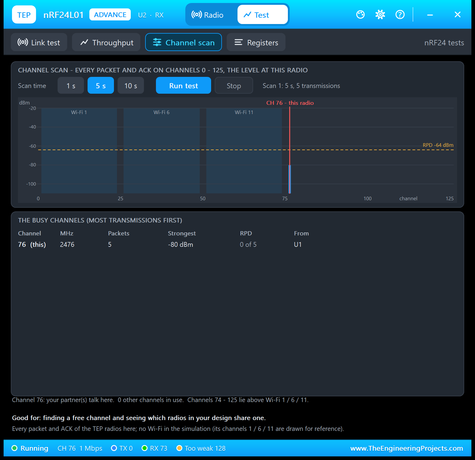
       Channel scan: 5 s, Run test - the busy channels.
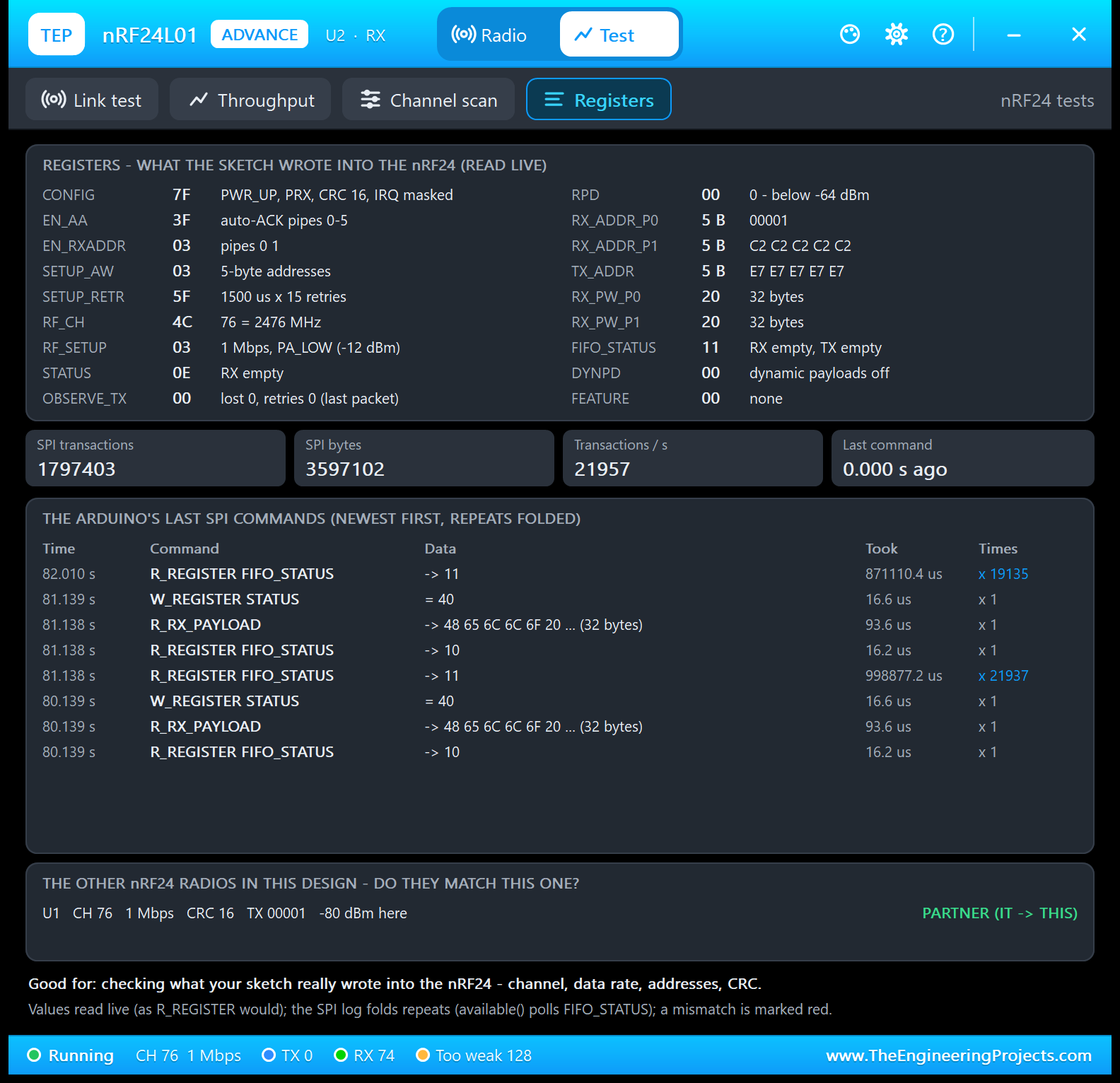
       Registers: what the sketch wrote, its SPI commands, U1 as its partner.
  5. Close U2's window and open it again with OPEN PANEL on the board.
Closed a monitor window? Click OPEN MONITOR on the monitor part.

WIRING (SPI, the same on both UNOs)
  nRF24L01 VCC -> supply (+5 V in the simulation - a real module needs 3.3 V!),
  GND -> GND, SCK -> D13, MISO -> D12, MOSI -> D11, CSN -> D10, CE -> D9, IRQ
  open (active LOW, for interrupt-driven sketches).
  In the sketch: RF24 radio(9, 10);   // CE, CSN
  Serial Monitor RXD <- Arduino D1 (TX), Serial Monitor TXD -> Arduino D0 (RX),
  Serial Monitor GND -> ground. RXD2 is not needed for SPI radios: the monitor's
  second input watches a serial line, and the nRF24L01 has none (it talks SPI).
  Serial.begin(9600) in the sketches.
Pin order in Proteus: VCC GND SCK MISO MOSI CSN CE IRQ (the real module's 2 x 4
header is GND VCC / CE CSN / SCK MOSI / MISO IRQ).
REAL HARDWARE:
 * Supply 1.9 - 3.6 V: feed VCC from 3.3 V, never from 5 V (the signal pins are
   5 V tolerant, so the UNO's SPI pins can be wired directly).
 * Put a 10 uF capacitor (10 - 100 uF) across VCC and GND right at the module -
   without it many modules fail with "no ACK" or reset while transmitting (the
   UNO's 3.3 V pin is weak; an adapter board with its own 3.3 V regulator helps).
 * Keep the PCB antenna clear of metal and away from the UNO; 2.4 GHz Wi-Fi uses
   channels 1 - 73 - channels above 100 are often quieter.

HOW THE RADIOS TALK (the model)
A packet arrives when the receiver is powered, listening (PRIM_RX = 1, CE high,
130 us settled), on the same channel, data rate, address width and CRC length,
with a matching enabled pipe address and payload size, its RX FIFO not full - and
the link budget is OK: level = TX power (RF24_PA_MIN -18 / LOW -12 / HIGH -6 /
MAX 0 dBm) - path loss (free space up to 1 m, then exponent 2.8: 68 dB at 10 m,
96 dB at 100 m at 2.4 GHz), against the sensitivity (-94 dBm at 250 kbps, -85 at
1 Mbps, -82 at 2 Mbps). The link uses the LARGER of the two radios' DISTANCE
settings. The ACK travels back the same way. Auto-ACK, retransmissions (ARD /
ARC), MAX_RT, the 2-bit packet ID (a retransmission whose ACK was lost is ACKed
again but stored once), dynamic payloads, ACK payloads, multicast (no ACK) and
the IRQ pin behave as in the nRF24L01+ Product Specification. RPD = 1 when the
level of a carrier on the channel is above -64 dBm. The demo (PA_LOW, 1 Mbps):
-80 dBm at 10 m (OK, 4.7 dB margin), too weak from 50 m; it reaches about 15 m.

THE TEST TOOLS (nRF24L01 Advance, Test tab) - what they really do
Every tool runs on the live model with your sketch and shows one "Good for:"
line plus one line on how it measures.
  Link test     Records the next 10, 20 or 50 packets THIS radio sends or hears
                (the sketch's real traffic): for each the retries (ARC), ACKed /
                lost (MAX_RT after 15) / no ACK asked, the level at the receiver,
                and whether the receiver stored it, heard it too weak, overloaded
                or dropped it as a duplicate. The DISTANCE buttons are on the tool,
                so you can move the radios while it runs. Below: the link budget at
                your data rate and PA level for a pair of plain modules and a pair
                of PA+LNA modules at every distance. Example (the demo, U2):
                10 packets ACKed at once at -80.3 dBm (+4.7 dB); then 100 m: lost
                after 16 attempts each (-108 dBm). No packet for 15 s stops it.
  Throughput    Two model radios in a private test air (your design never hears
                them), at this radio's DISTANCE and PA level, stream 100 packets
                like RF24's writeFast() (the TX FIFO kept full, CE high): measured
                packets / s, payload bytes / s, the time per packet (130 us
                settling + the packet's bits + the ACK), plus a table of all three
                data rates with auto-ACK on and off. Measured at 10 m, 32 bytes:
                250 kbps 535 / 692 packets/s (17.1 / 22.1 kB/s), 1 Mbps 1511 / 2179
                (48.3 / 69.7 kB/s), 2 Mbps 2132 / 3350 (68.2 / 107.2 kB/s) with /
                without ACK. A real UNO adds its SPI time. Below: your sketch's own
                traffic of the last 5 s.
  Channel scan  Listens on all 126 channels for 1, 5 or 10 s: every packet and
                ACK of the TEP radios in the design, the strongest level at this
                radio per channel and how often it was above -64 dBm (RPD), with
                the Wi-Fi channels 1 / 6 / 11 drawn for reference (there is no
                Wi-Fi in the simulation) and a list of the busy channels and who
                uses them. (The radio's own ACKs are not counted.)
  Registers     The registers read live as R_REGISTER would (CONFIG, EN_AA,
                EN_RXADDR, SETUP_AW, SETUP_RETR, RF_CH, RF_SETUP, STATUS,
                OBSERVE_TX, RPD, the addresses, RX_PW, FIFO_STATUS, DYNPD, FEATURE)
                with their meaning, the SPI counters, the Arduino's last SPI
                commands (time, command, data, duration; identical commands in a
                row folded - RF24's available() polls FIFO_STATUS) and THE OTHER
                RADIOS: does each match this one (channel, data rate, CRC, address
                width, address, payload size, level here)?

THE DEMO SKETCHES ON THE SERIAL MONITOR (NRF24_Transmitter / NRF24_Receiver v1.1)
  SEND <text>             a message to the other node now (up to 31 characters)
  PING                    the other node answers PONG - prints the round trip
  STATUS                  channel, frequency, data rate, PA level, CRC, chip OK,
                          addresses, counters
  CH <0-125>              radio channel (type it on both monitors)
  RATE <250K|1M|2M>       data rate (both)
  PA <MIN|LOW|HIGH|MAX>   transmit power
  AUTO <ON|OFF>           (transmitter) the Hello TEP message every second
  HELP                    the command list
Monitor quick buttons in the demo: PING, STATUS, SEND Hello from node 1 / 2, HELP.
Node 1 sends to address 00001 and listens on 00002 between its packets; node 2
listens on 00001 and sends to 00002.

EXPECTED MONITOR OUTPUT (from the PC test of the real sketches)
U3 (UNO 1, transmitter):
  TEP nRF24L01 Transmitter Demo v1.1
  Radio ready: channel 76, 1 Mbps, address 00001
  Type HELP in the Serial Monitor for the commands
  Sent: Hello TEP #1  -> ACK received
  Sent: Hello TEP #2  -> ACK received
  PING: PONG from node 2 after 1.5 ms
  Received from node 2: Hello from node 2
  Status: channel 76 (2476 MHz), 1 Mbps, PA LOW, CRC 16, radio OK
    sends to 00001, listens on 00002, auto-send ON (every 1 s)
    sent 5, ACK 5, failed 0, retries 0, received 0
  Link (10 s): 10 sent, 10 ACK, 0 failed, 0 retries
  Sent: Hello TEP #12  -> FAILED, no ACK          (100 m)
U4 (UNO 2, receiver):
  TEP nRF24L01 Receiver Demo v1.1
  Listening: channel 76, 1 Mbps, address 00001
  Received #1: Hello TEP #1
  Received #7: PING
    -> PONG sent back
  Sent: Hello from node 2  -> ACK received
  Link (10 s): 10 received, 0 sent

PROPERTIES
The module has no user properties: the sketch sets channel, data rate, power and
addresses over SPI (as on the real chip), and the DISTANCE is chosen on the panel
(10 m at every Run). The panel style is chosen by the device (Simple / Advance).
The Advance window settings (theme, text size, open at Run, size) are on its
Settings page. The demo's Serial Monitors: BAUD 9600, THEME TEPDARK, AUTOOPEN
YES, QUICK1-4 as above (see the Serial Monitor's article for all its properties).

LINKS.INI (OPTIONAL)
The Help page cards of the Advance device open web pages. To point them
somewhere else without a new DLL, put a text file named links.ini next to
TEPNRF24L01.DLL with lines KEY=URL, for example:
  ARTICLE=https://www.theengineeringprojects.com/...
Keys: WEBSITE, FORUM, BUG_REPORT, FEATURE_REQUEST, ARTICLE, USER_GUIDE,
UPDATE_CHECK, DONATE. Only http:// and https:// links are used; lines starting
with # are comments. Cards whose link is not published yet say "Link coming soon".

TROUBLESHOOTING
* "nRF24L01 not responding - check the SPI wiring and power": check SCK D13,
  MISO D12, MOSI D11, CSN D10, CE D9 and VCC / GND, and that TEPNRF24L01.DLL is in
  MODELS (and beside the project).
* Always "FAILED, no ACK": the receiver must listen (its panel says RX -
  LISTENING) on the same channel, data rate and address; both DISTANCE settings
  count (the larger one is used) - at PA_LOW / 1 Mbps the link ends at about 15 m.
  The Registers tool lists what does not match.
* CH / RATE typed on one monitor only: the link breaks until the other node uses
  the same setting.
* Two PA+LNA modules 1 m apart at PA MAX: the receiver overloads (use PA LOW).
* The part is not simulated / no panel: TEPNRF24L01.DLL is missing from MODELS
  and from the project folder. No monitor window: TEPSERIALMON.DLL is missing, or
  click OPEN MONITOR on the monitor part.
* Advance: the pop-up does not appear - click OPEN PANEL on the module board,
  use Proteus's Debug menu, or turn "Open the panel at Run" on its Settings page
  back on.
* Simple: the red X does not close the panel - the design still holds the v1.0
  symbol; replace TEPNRF24L01.LIB, delete TEPNRF24L01.IDX and re-pick the part.
* Your own sketch: Proteus 8.5's UNO runs the hardware SPI of the RF24 library
  fine; only SoftwareSerial cannot receive in Proteus 8.5 (no pin-change
  interrupts) - not needed here.

BUG REPORTS AND FEATURE REQUESTS
Please post them in our forum with a screenshot, the Serial Monitor text, the
simulation log and (Advance) the Copy diagnostics text:
  https://www.theengineeringprojects.com/forum/category/nrf24l01-proteus-library

SUPPORT US
This library is free. If it saves you time, please support our work:
  https://www.theengineeringprojects.com/donate

WEBSITE
  https://www.theengineeringprojects.com/

LICENCES AND THIRD-PARTY NOTES
* The nRF24L01 model (TEPNRF24L01.DLL), the symbols and artwork and the TEP Serial
  Monitor Advance (TEPSERIALMON.LIB / .DLL) are made by The Engineering Projects.
  The model is an inde
…Development1 release
 Development1 release
-
V1.1nRF24L01 Library for Proteus V1.1this page
V1.1 is the only release in the Download Center so far. When a newer version is published, it appears above with its own download page.
Installation11 steps
 Installation11 steps
From the download to a working project, in order. The steps follow what the package contains.
You will need
- Proteus Design SuiteProteus 8 or newer (Labcenter), on Windows
- Arduino IDE1.8 or 2.x, with the board of the tutorial chosen under Tools → Board
- The compiler named in the tutorialto build the source files into firmware
- Any archive toolWindows, macOS and Linux extract ZIP files on their own

Steps
- 1
Extract the archive
Right-click nrf24l01-tep-v1-1-367f6cce25d540b2a9320bcf77ac087b.zip and choose Extract All (or open it with 7-Zip or WinRAR) into a folder you can find again. Keep its folder structure (NRF24L01-TEP-v1.1) as it is.
- 2
Copy the library files into Proteus
Move ArduinoV3TEP.LIB, TEPNRF24L01.LIB and TEPSERIALMON.LIB and ArduinoV3TEP.IDX into the LIBRARY folder of your Proteus installation: C:\Program Files (x86)\Labcenter Electronics\Proteus 8 Professional\LIBRARY for Proteus 8, or the matching Proteus 7 folder. Older versions keep it under ProgramData\Labcenter Electronics. If Proteus is open, close it first.
- 3
Add the simulation model
Copy TEPNRF24L01.DLL and TEPSERIALMON.DLL into the MODELS folder next to LIBRARY, so the component can run, not only be drawn.
- 4
Restart Proteus and place the component
Start Proteus, open a schematic, press P (Pick Devices) and search for the component by the name used in the tutorial. It appears with its pins ready to wire.
- 5
Install the Arduino library
In the Arduino IDE choose Sketch → Include Library → Add .ZIP Library and pick the library, or copy its folder into Documents\Arduino\libraries. Restart the IDE to see its examples.
- 6
Open the sketch in the Arduino IDE
Open NRF24_Receiver.ino, NRF24_Transmitter.ino and AcknowledgementPayloads.ino and 19 more, select your board and port under Tools, then Verify. Sketch → Export Compiled Binary writes the HEX file a simulation needs.
- 7
Build the source code
Open print_details.py in the compiler named in the tutorial (MikroC, Keil, MPLAB, Code Composer or the Arduino IDE) and build it to get the firmware.
- 8
Load the HEX file
In Proteus double-click the microcontroller, set Program File to NRF24_Receiver.hex and NRF24_Transmitter.hex and run the simulation. For real hardware, flash the same file with your programmer.
- 9
Open the example simulation
Open NRF24L01-ArduinoUnoV3.pdsprj in Proteus to see the wiring exactly as in the tutorial. Check the controller's Program File path, then press Play.
- 10
Use the data files
library.json hold the readings or settings the project uses; open them with Excel, a text editor or the script of the tutorial.
- 11
Follow the tutorial
nRF24L01 Library for Proteus V1.1 (2.4 GHz RF + Arduino) explains every connection and setting in order; keep it open beside the files while you build.
FAQs9 questionsContact TEP
 FAQs9 questions
How do I download nRF24L01 Library for Proteus V1.1?
Wait for the 30-second guest countdown on this page, then press the download button; the file comes straight from our storage. Members who are logged in skip the wait. If the browser opens the file instead of saving it, use its Save as option. The download link is made for you when the countdown ends and works for 15 minutes; a saved or shared link stops working, so share this page instead.
What is inside the archive?
nRF24L01 Library for Proteus V1.1 comes as a ZIP archive of 121 files (1.6 MB, 3.7 MB unpacked) holding Proteus library files, simulation model DLLs, a Proteus simulation, an Arduino sketch, an Arduino library, compiled HEX firmware, source code and data files. Open the File Structure tab for the full list of 121 files.
What should I do if the download does not start?
Check the browser's download list first; an ad blocker or a company firewall can also hold it back, so try another browser or network. If the file arrives incomplete, download it again. For an installation problem, read the Install tab or tell us in the comments with your software version and the exact error message.
Is this file free?
Yes. Every file in the TEP Download Center is free for learning, personal and student projects. If you share it, link back to this page or the tutorial so others find the latest version.
How do I check that the file arrived complete?
Compare its SHA-256 with the one on this page, eded5653e76c55345eb39f7080c53861c0701b562831df8f125b7fea7ffc395e. In PowerShell run Get-FileHash "nrf24l01-tep-v1-1-367f6cce25d540b2a9320bcf77ac087b.zip"; on macOS or Linux run shasum -a 256 "nrf24l01-tep-v1-1-367f6cce25d540b2a9320bcf77ac087b.zip". The same value means the file is exactly the one in our storage; a different one means the download broke off, so download it again.
Do I need WinRAR to open the ZIP file?
No. Windows, macOS and Linux open ZIP archives on their own (Extract All, or double-click). WinRAR and 7-Zip work too. Extract the whole archive before using the files.
Where do I put the LIB and IDX files?
Both files go into the LIBRARY folder of your Proteus installation (Proteus 8: C:\Program Files (x86)\Labcenter Electronics\Proteus 8 Professional\LIBRARY; Proteus 7 has the same folder under its own name). Restart Proteus afterwards and search for the component with P.
Which Proteus version does the library need?
The tutorial names the Proteus version the library was made and tested with. Most TEP libraries work in Proteus 7 and Proteus 8; if the component does not appear after a restart, check that both the LIB and the IDX file were copied and that Proteus was fully closed while copying.
How do I get the HEX file into the simulation?
Compile the sketch in the Arduino IDE (Sketch → Export Compiled Binary gives you the HEX next to the sketch), then in Proteus double-click the board, set Program File to that HEX and run.
Members skip the wait. Log in or join TEP.

- 14Total downloads
- 4%Popularity
- ProteusCategory
- 0Comments
- ssyedzainnasirUploaded by
- 21 Sep 2026Uploaded at


 SHA-256
eded5653e76c55345eb39f7080c53861c0701b562831df8f125b7fea7ffc395e


 Need help with this file?
 Tags
Related Proteus
All Proteus tutorials


Comments
0