

Hello friends, hope you all are fine and enjoying. Today i am going a new project tutorial which is 11-level 3-phase Capacitor Clamped Inverter. In my previous post 11 Level 3-phase Cascaded H-Bridge Inverter, we have designed the simulation of 3 phase 11 level inverter but the only difference was the method used in that project was cascaded H Bridge but today we are gonna see How to design an 11 level 3 phase inverter using clamped capacitors.
Now i am going to share a new and advanced bulk of knowledge about inverters with you people. Since we are going to design a 3-phase capacitor clamped inverter so, we need to design some algorithm which should be able to invert DC into AC at some High voltages and after inverting these DC voltages into AC, we will create a phase sequence and most importantly phase polarity between these three phases so they should be able to feed the load and must supply load current. It is a very interesting but a bit complicated project and now-a-days it has got a large no of industrial applications. The study about inverters and their implementation is the back bone of Modern Renewable Energy and it is the future of Power Generation. It is a MATLAB simulation based project so, any kind of hardware is not included in this tutorial. So what actually we are going to do is to design the complete simulation of the project and we will discuss every component and also each sub-component which will be used in Simulink MATLAB. So let's get started with 11 Level 3 Phase Capacitor Clamped Inverter:
11-level 3-Phase Capacitor Clamped Inverter
- Capacitor Clamped inverters are commonly known as Flying Capacitor Technology and they were first purposed by Meynard and Foch.
- Flying Capacitor includes no of series combination of Capacitor Clamped Inverter Switching Cells and these capacitors are used to get high voltages.
- The general concept related to flying capacitor is that it can charge up to one-half of the DC voltages and then within the circuit they can automatically increase or decrease the voltages, according to our requirement.
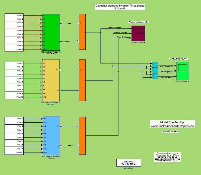
- The block diagram of the complete simulation of capacitor clamped inverter in MATLAB is given in the image below:
- The complete block diagram of the Capacitor 3-phase clamped inverter is shown above. In this image, you can notice that we have 30 input pulses numbered as no.1 to no.30 .
- So we can say that we have 30 DC input pins and these DC voltages will be inverted to get High Voltage AC.
- If you double click on any input pulse then, a new window will open and it will be showing that source from which we are gaining input DC voltages.
- We are gaining DC voltages from DC generators and a no of generators are connected in parallel to get HIGH voltage DC.
- The block to which all the inputs are connected is in fact a Capacitor Clamped Bank.
- In this bank, no. of capacitors are connected in series. Since a charged capacitor behaves as a voltage source and these capacitors are connected in series and their voltages adds up and in this way we get, HIGH voltages.
- To look inside the block then double click on the block and a new window will open and it will be showing all the components which are fabricated in that block.
- The internal structure of the block for capacitor clamped inverter is shown below in image:
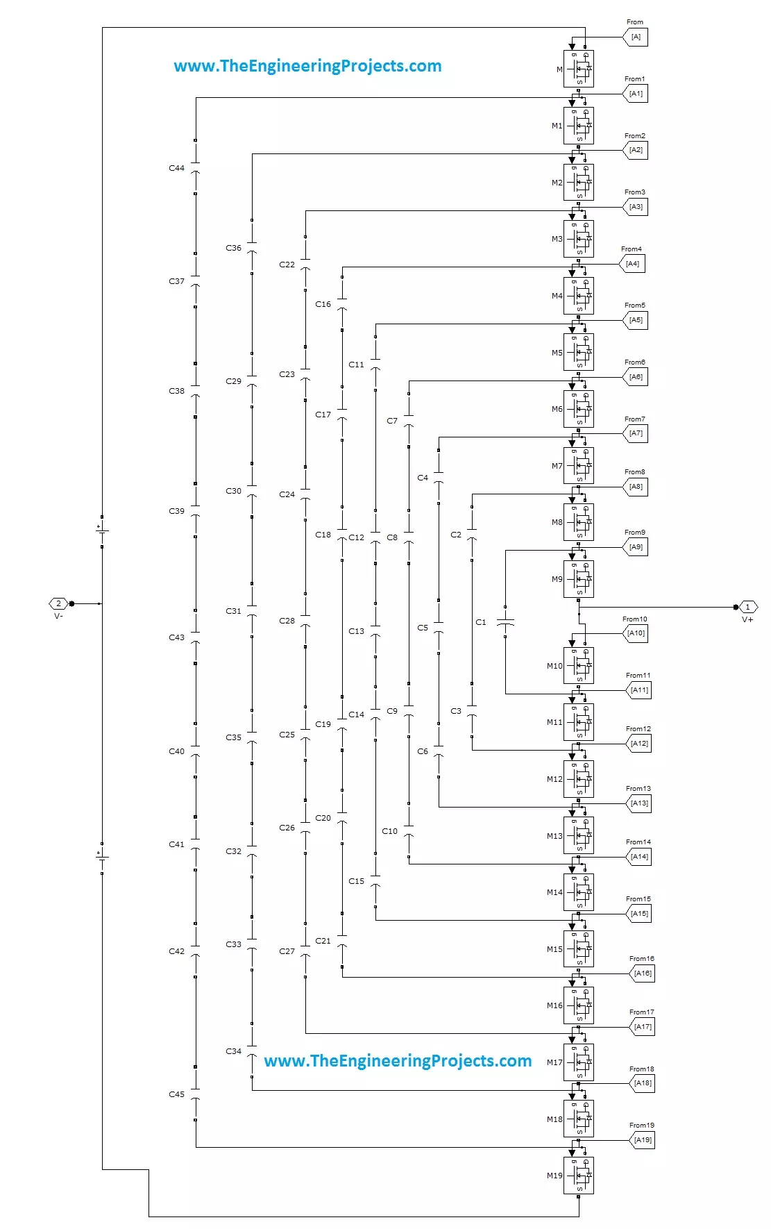
- In the above shown image, you can see that within the block, we have a no. of sub-blocks which are connected with each other.
- To see what is in that small box, double click on that and a new window will open, which will be showing the internal structure of the each small box.
- The internal structure of sub-block is shown in the image given below:

- In the above given figure you can see that, in every block we have a MOSFETS which are connected with antiparallel diodes for capacitor clamped inverter.
- Ideal IGBT or GTO transistors can also be used but as I explained the properties of MOSFET in the beginning, that we give pulse to its base and it becomes operational.
- Once MOSFET has been triggered it keep conducting and in order to stop it, we will have to provide reverse voltage on its base to bring it to rest state.
- Since we are going to generate High Voltages 3-phase AC, so we have applied 3 big blocks and from each block, only one phase will be generated.
- After each big block, we have a summing junction on which voltages arrives and then we have applied two different types of voltage measuring devices.
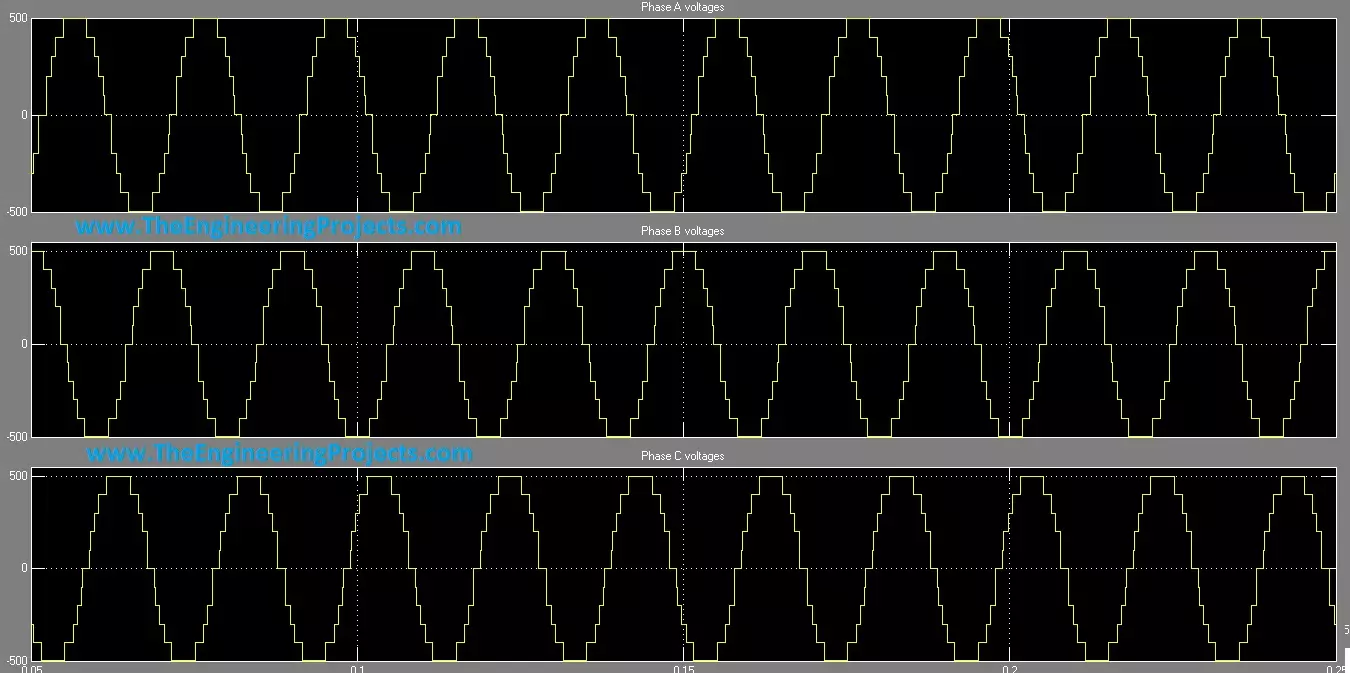
- One device measures the phase voltages of inverted AC voltages. It can also be seen from the above given block diagram that the meter on the above side, measures phase voltages of all the three phases appearing on the summing junction.
- Now if you look closely then, you will observe that only one wire from each summing junction is coming to the meter and we also know that in order to measure phase voltages, we also need a neutral wire.
- We can get neutral wire from common ground of the system and the voltage difference between a phase and a neutral wire will give us Phase voltages.
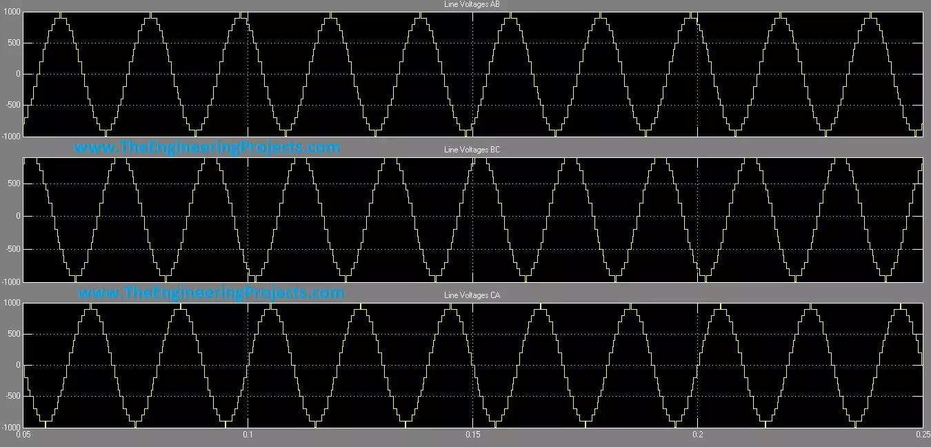
- The below meter measures line voltages. Line voltages means the voltage difference between 2 phases. In our system we have three phases which are A, B and C respectively.
- To measure line voltages, this meter measures potential difference between phases and NO neutral wire is included in it.
- The line voltages will be AB, BC and CA.
- The Phase voltages and Line voltages have much difference between them and each have their own applications.
- For example to run the single phase House-Hold load we need phase voltages (voltage difference between a phase and a neutral wire).
- Whereas in industries, we need Line voltages to run the 3-phase load.
- Now run the simulation of this capacitor clamped inverter, and after completion now click on the scope for Line Voltages and you will get the below results:
- Now for Phase voltages of capacitor clamped inverter, click on the scope for phase voltages and you will get the below results:
APPLICATIONS
All type of Inverters have a large no of applications and now a days they are focus of Research and modern studies. Inverters have also made us able to get power from Renewable energy sources like solar panels, wind mills etc. Some industrial based applications of inverters are given below:- The biggest advantage of inverters are that they give good power quality.
- Due to good power quality motors can reach at High speed at High voltages without producing any harmonics.
- They are used in power supply circuits.
- Now-a-days inverter Air Conditioners are also available in market and due to their High Efficiency and low power rating their demand is much High.
- ECU( electrical control unit) which carries out in-vehicle control also carries inverted circuits and it's demand is also accelerating these days.
