Traffic Light Circuit using 555 Timer in Proteus


- What is the Traffic Lights circuit with 555 Timer?
- What does the 555 timer do in Traffic Lights?
- What is the purpose of the 4017 IC Counter in the circuit?
- How does the circuit of Traffic Lights work with 555 Timer IC?
- How can we perform experiments with the circuit of 555 Timer Traffic Lights in Proteus ISIS?
In addition, we'll see some important points about the topic in DID YOU KNOW sections.
Traffic Lights circuit with 555 Timer
Whenever we rush toward any road that has a heavy flow of vehicles, we always follow some traffic rules. One of the most fundamental traffic rules is to follow the traffic lights. These traffic lights direct the vehicles to start or stop moving at the road according to our turn. These turns are decided by the Traffic Lights. The traffic Lights show the different colored lights and these lights turn on and off in a sequence. We know all these things, but we are revising these to get the logic behind the scene. we define the Traffic Lights technically as:
"The traffic lights are the combination of three LEDs colored as red, amber and green that are connected in a specialized circuit that gives the output from the LEDs in a specific format and this format is used to control the flow of traffic."
These LEDs are enclosed in a metallic body. Traffic Light signals are so useful that 99% of the countries use them. This makes the circuit one of the most fundamental and common circuits to understand.
There are many devices through which the Traffic Lights may be controlled. Out of which, two are common:
- Traffic Lights with the D Flip Flop.
- Traffic Lights with 555 Timer
We have discussed the 1st method in our previous tutorial, Let's have a look at the next one.
555 Timer IC Performance in Traffic Lights
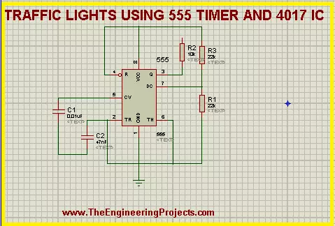
before starting the simulation, let's have a look at its components briefly. The circuit of Traffic Lights uses a very common yet powerful device i.e, 555 Timer IC. The 555 Timer is so useful that it is said that annually, a billion of 555 Timers are produced and it is considered as the most popular IC of the year 2017. We introduce the 555 Timer as:
"The 555 Timer is a common 8 pins Integrated Circuit used in a variety of oscillation generators and Timers to generate a pulse of the signals that control the output sequentially."
In our experiment, we'll apply the Mono-stable Multi-vibrator mode of the 555 timer. The output of 555 Timer in this mode is in the form of a single pulse of current that has a specific length. This pulse is sometimes called the one-shot pulse.
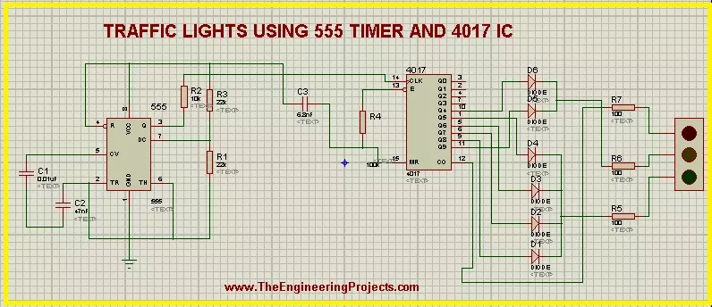
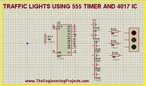
4017 IC in the 555 Timer Traffic Lights
The 4017 is the special IC that is usually coupled with the 555 Timer. It works on the pulse generated by the 555 Timer and the definition for the 4017 IC is given as:
- "The 4017 is 16 pins counter and decoder of 555 Timer IC that generates a decade counter output from its output pins and the outputs advances from one to another with the positive edge of the clock pulse."
Once the clock pulse of 4017 IC in the traffic Lights goes from low to high, the IC started its cycle again and we get a sequential Logic output. The pins 3 to 12 of the 4017 IC Counter are said to be the output pins of the 4017 and we'll connect the traffic lights with them.
Working of Traffic Lights using 555 Timer IC
- The Working of the circuit starts with the power connected to the Vcc terminal of 555 Timer IC.
- the power in the 555 Timer in Mono-stable Multi-vibrator mode produces a uniform pulse of current that is stabilized with the help of capacitors used with the 555 Timer IC.
- The current is then fed into the clock terminal of the 4017 decade counter IC that decodes these pulses of 555 Timer IC and produces the stream of output at its output terminals.
- The terminals of the 4017 IC are connected to the diodes in a specific manner. These diodes conduct the electricity on only one side and so that a specialized sequence of the current is found at the outputs of these diodes.
- There are two sets of the diode connections. Four diodes are connected in a set and two in another. The output of 1st set is fed to Green Light of the Traffic Lights. The Amber and Red lights of the circuit are connected with the second set.
- The output of these two sets is connected with the resistor and then finally this current passes to the traffic Lights signal.
- In the end, we get a specialized, clear and automatic output from the traffic lights.
Simulation of the circuit of 555 Timer Traffic Lights in Proteus ISIS
At the moment, we are going to design the circuit of the experiments. So let's start.Devices required for 555 Timer Traffic Lights
- 555 Timer IC
- 4017 IC
- Capacitors - 3
- Resistors - 7
- Diodes - 6
- Traffic lights
- Fire up your Proteus Software.
- Choose the material from pick Library through "P" button.
- 555 Timer connections
- 4017 IC Counter connections
- Connection of 555 Timer and 4017 IC
555 Timer Connections
- Choose the 555 Timer from the component's area and arrange it on the left side working area.
- Select the resistor then arrange three resistors with pin 3, 6 and 7.
- Take capacitor and set two capacitors with pin 2 and 5 of 555 Timer.
- Go to terminal mode and set a Ground terminal at the Ground pin of the 555 Timer.
- Connect all the components of 555 Timer IC as:
Connections of 4017 IC
- Go to components, choose 4017 IC.
- Select diode and arrange the 7 diodes with the output pins on the right side of 4017 IC.
- Take care with the direction of the diodes.
- Set a resistor between the pins 13 and 16 of 4017 IC.
- Arrange three resistors just after the diodes.
- Now set a Traffic Light signal on the right side of the resistors.
DID YOU KNOW?????????????????????????????
It is said by AAA, the average American spends 58.6 hours every year waiting at the red light of traffic signal.
- The circuit now looks like the image given next:
Connection of ICs
- Now, at the moment, we'll connect the ICs to finally set our circuit.
- Set a capacitor between both these ICs.
- Alter the names of the components by given them numbering so that Proteus may distinguish between different Resistors, Capacitors, diodes and ICs.
- Change the values of each component according to the table given next:
| Component | Values |
| C1 | 0.01uF |
| C2 | 47uF |
| C3 | 6.8nF |
| R1 | 23k ohm |
| R2 | 10k ohm |
| R3 | 22K ohm |
| R4 | 100k ohm |
| R5 | 100 ohm |
| R6 | 100 ohm |
- Observe deeply the image given below and connect all the components with the help of connecting wires.
- Our circuit is now good to go, Let's tap the play button and simulate the circuit.
So, today we saw a fantastic circuit in which we learned that what are the Traffic lights signal using 555 timer, how does the ICs of 555 timer and 4017 IC Counter work with each other to show the output of the Traffic Lights and we designed the circuit of 555 Timer Traffic Lights in Proteus ISIS. If you have any questions, you can contact us through the comment sections.DID YOU KNOW????????????????
The working speed of the Traffic Lights can be varied by changing the values of capacitors connected with pin 5 and 2 of the 555 Timer IC.