


Inline Natural Gas Flow Meter: Installation, Commissioning and Maintenance Guide


Natural gas is the fuel behind boilers, furnaces, ovens, dryers, kilns and gas engines in thousands of plants, and the amount burned is usually one of the largest running costs on site. Measuring it accurately tells you what each process really consumes, shows when a burner starts to waste fuel and gives you reliable numbers for energy reports and cost allocation.
A well-chosen inline natural gas flow meter only delivers its rated accuracy when it is installed, wired and commissioned correctly. Many complaints about meters that "read wrong" are really installation problems: a meter placed straight after an elbow, a configuration made for the wrong gas, or an analog signal scaled differently at the meter and in the control system.
This guide walks through the practical side: what an inline meter is, which data to collect before you buy and install one, how to lay out the pipe run, what to check during commissioning and how to keep the meter accurate over the years. If you are still comparing measuring principles, our overview of gas flow meter types explains thermal, Coriolis, differential pressure, turbine and ultrasonic meters in detail.
What Does "Inline" Mean?
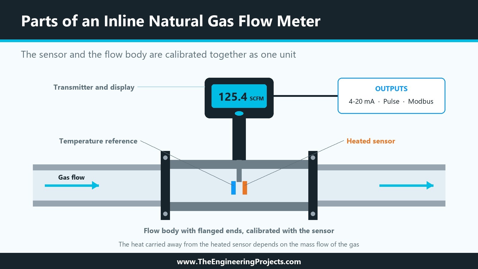
An inline meter has its own flow body, a short section of pipe with flanged or threaded ends, that is installed in the line in place of a piece of pipe. The sensor sits at a fixed position inside a bore of known size, and the manufacturer calibrates the sensor and the flow body together as one unit. That is the main advantage: the relationship between what the sensor sees and the actual flow through the pipe is fixed in the factory rather than estimated on site.
The alternative is an insertion meter, a probe pushed into an existing pipe through a fitting. Insertion probes are attractive for large pipes because the cost hardly changes with pipe size, but their accuracy depends on knowing the real inside diameter of the pipe and on placing the probe at the right depth. For small and medium lines, an inline meter is usually the simpler and more accurate choice.
Many inline meters for natural gas use the thermal mass principle. A heated sensor and a temperature reference sensor sit in the gas stream, and the heat carried away by the flowing gas depends on its mass flow. Because the meter responds to mass flow, it can show the result directly as standard volume, for example in standard cubic feet per minute (SCFM) or normal cubic metres per hour (Nm³/h), without separate pressure and temperature transmitters. Volumetric meters such as turbine, rotary or vortex meters measure the actual volume at line conditions and need pressure and temperature correction to report standard volume.
Data to Collect Before Installation
Good results start before the meter is ordered. Collect the following information and share it with the supplier:
- Gas composition: pipeline natural gas, biogas or a blend. Thermal meters are calibrated for a specific gas mix, so the composition matters.
- Flow range: the minimum, normal and maximum flow. Size the meter for this range rather than simply matching the pipe size; an oversized meter spends most of its life at the bottom of its range.
- Operating conditions: line pressure and gas temperature, including their extremes.
- Pipe details: nominal size, schedule and end connections.
- Signals and power: the outputs your control system expects (4-20 mA, pulse, Modbus RTU over RS-485 or HART) and the available supply voltage.
- Area classification: whether the meter will sit in a hazardous area and which approval it therefore needs.
- Purpose of the reading: energy monitoring and cost allocation inside a plant, or billing between companies. Billing usually requires meters and installations approved under the applicable metrology rules.
Also agree on the base conditions for standard volume. Standard cubic feet are often referenced to 60 °F and 14.696 psia in the US gas industry, while normal cubic metres commonly use 0 °C and 1.01325 bar. A meter configured for one convention and compared with a utility bill that uses another will show a constant, confusing offset.
Pipe Runs and Mounting
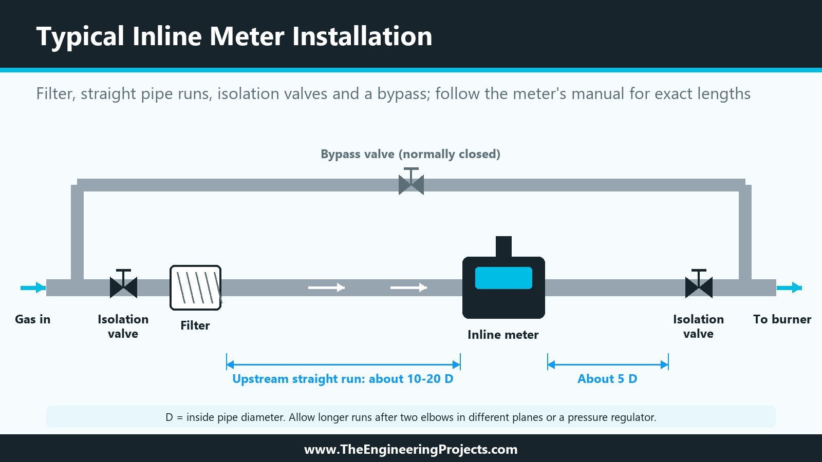
Elbows, valves, reducers, tees and especially pressure regulators disturb the flow profile, adding swirl and an uneven velocity across the pipe. A meter placed in that disturbed flow can read high or low even when it is working perfectly. Many manufacturers ask for about 10 to 20 pipe diameters (D) of straight pipe upstream of the meter and around 5 D downstream, with longer runs after two elbows in different planes or after a regulator. A flow conditioner can shorten the required run. Always follow the installation manual of the specific meter, because the figures differ between designs.
Some further rules make the installation easier to live with:
- Install a filter or strainer upstream, so dust, pipe scale and oil droplets do not reach the sensor.
- Fit isolation valves on both sides and, where your procedures allow it, a bypass with its own valve, so the meter can be removed for cleaning or calibration without shutting off the gas supply.
- Check the flow direction arrow on the body and mount the meter in the orientation the manual specifies.
- Avoid low points where condensate can collect, and support the pipe so the meter does not carry pipe stress.
- Use gaskets of the correct size: a gasket that protrudes into the bore disturbs the flow right at the sensor.
Wiring and Safety
Areas around gas trains and meter runs are often classified as hazardous. Choose a meter with the approval the area requires, for example ATEX or IECEx zones or Class I, Division 1 or 2 in North America, and install it according to the wiring rules of that approval, including cable glands, conduit seals or barriers. Bond and earth the meter and the pipe, use shielded cable for analog and RS-485 signals, and route signal cables away from motor and variable frequency drive power cables.
Work on gas lines must be done by qualified personnel. After installation, the line has to be purged and leak tested according to local codes before the meter is put into service.
Commissioning Checklist
Before you rely on the readings, go through these steps and record the results:
- Confirm the configuration: gas type, flow units, base conditions and the full-scale range.
- Check the 4-20 mA scaling, so that 4 mA and 20 mA mean the same flow in the meter and in the PLC or building management system.
- Check the reading at no flow with the line full of gas, if the meter supports a zero check.
- Compare the reading with a reference, such as the utility meter or the known consumption of a burner at a fixed firing rate.
- Reset or note the totalizer, and save a copy of the final settings.
Maintenance and Calibration
A thermal sensor measures heat transfer, so anything that coats the sensor changes its response. Dust, oil mist and condensate are the usual causes of slow drift. Inspect and clean the sensor at the interval the manufacturer recommends, and replace filter elements before they clog. Many plants verify or recalibrate their meters once a year, or at the interval their quality system requires, and keep the certificates with the meter records.
Watch for warning signs between checks: a reading of zero while a burner is firing, a noisy signal at steady load, or a sudden step change after maintenance work on the pipe. Each of these is a reason to check the meter before trusting its totals.
Common Installation Mistakes
| Mistake | Effect | Fix |
|---|---|---|
| Meter straight after an elbow, valve or regulator | Distorted flow profile, wrong reading | Add straight pipe or a flow conditioner |
| Wrong gas or base conditions in the setup | Constant offset against the utility meter | Set the gas mix and the agreed base conditions |
| Meter sized for the pipe, not the flow | Low flows near the bottom of the range | Size the meter for the real flow range |
| No filter upstream | Sensor fouling and slow drift | Install a filter and inspect it regularly |
| Different 4-20 mA ranges at both ends | Wrong values in the control system | Match the scaling in the meter and the PLC |
Conclusion
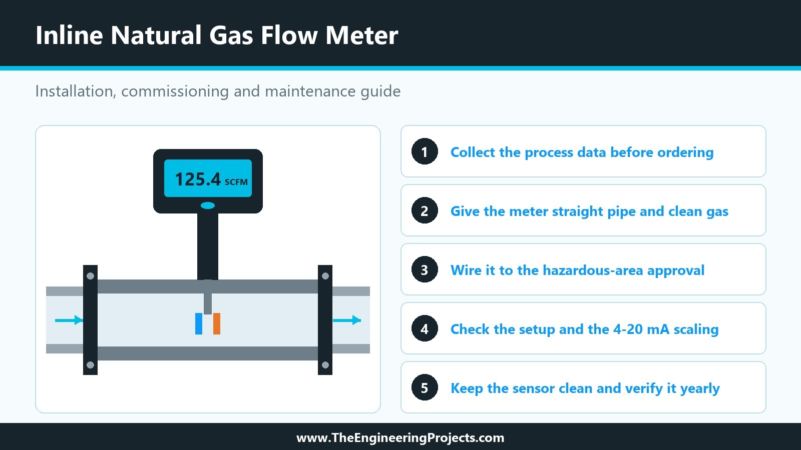
An inline meter gives you a factory-calibrated measurement of the gas your processes burn, but only if the installation lets it work as designed. Collect the process data before ordering, give the meter straight pipe and clean gas, wire it according to the area approval, check the configuration and the signal scaling during commissioning, and keep the sensor clean. With these basics in place, the readings become a dependable tool for cutting fuel costs and spotting problems early.

Comments
0