PWM stands for Pulse-Width Modulation. Once the switching frequency (fsw) has been chosen, the ratio between the switch-on time (TON) and the switch-off time (TOFF) is varied. This is commonly called duty-cycle (D). The duty cycle can be between 0 and 1 and is generally expressed as a percentage (%).
D = TON / (TON + TOFF) = TON x fsw
The variation of the pulse width, made at a high frequency (kHz), is perceived as continuous and can be translated into a variation of the rotation speed of a motor, dimming a LED, driving an encoder, driving power conversion, and etc. The use of PWM is also widely used in the automotive sector in electronic control units (ECU - Electronic Control Unit) to manage the energy to be supplied to some actuators, both fix ...
A Digital to Analog Converter(DAC) performs the task of converting digital words of n bits into voltages whose amplitude will be proportional to the value of the code expressed by the words themselves. Since the input binary words represent a succession of finite codes, the voltage coming out of a DAC cannot be continuous over time but is made up of as many levels as the converted codes are. This means that the devices to which the analog signal produced by a DAC is sent must filter it with a low-pass characteristic (integrating action). The operating criterion of a DAC is simple: in fact, it is sufficient to have a succession of as many voltages as there are convertible codes, obtained for example by means of a weighted resistance network (i.e. t ...
An Analog to Digital Converter (ADC) converts a continuous signal (usually a voltage) into a series of discrete values ??(sequences of bits). The main features are:
Resolution (in analog terms): It is the minimum variation of the analog input voltage that can determine the variation of the LSB, that is of the least significant bit of the output code. Since the quantization step Q corresponds to the LSB, it can be said that the resolution coincides with the quantization step Q (and therefore is measured in Volts). We can say that the quantization step Q corresponds to the LSB because two contiguous quantization bands, each of amplitude Q, are identified by codes that differ only for the least significant bit.
Resolution (in digital terms): It is the number n of bits present at the co ...
The SPI (Serial Peripheral Interface) protocol, or rather the SPI interface, was originally devised by Motorola (now Freescale) to support their microprocessors and microcontrollers. Unlike the I2C standard designed by Philips, the SPI interface has never been standardized; nevertheless, it has become a de-facto standard. National Semiconductor has developed a variant of the SPI under the name Microwire bus. The lack of official rules has led to the addition of many features and options that must be appropriately selected and set in order to allow proper communication between the various interconnected devices. The SPI interface describes a single Master single Slave communication and is of the synchronous and full-duplex type. The clock is transmitted with a dedicated line (not necessari ...
EEPROMs (Electrically Erasable Programmable Read-Only Memories) allow the non-volatile storage of application data or the storage of small amounts of data in the event of a power failure. Using external memories that allow you to add storage capacity for all those applications that require data recording. We can choose many types of memories depending on the type of interface and their capacity.
EEPROMs are generally classified and identified based on the type of serial bus they use. The first two digits of the code identify the serial bus used:
Parallel: 28 (for example 28C512) much used in the past but now too large due to having many dedicated pins for parallel transmission
Serial I2C: 24 (for example 24LC256)
Serial SPI: 25 (for example 25AA080A)
Serial - Microwire: 93 (for ...
Hello friends, I hope you all are doing great. In today's lecture, we will have a look at the I2C Communication with STM32 Microcontroller board. I am going to use the Nucleo board for today's lecture. In the previous lecture, we have discussed STM32 Serial communication both in Interrupt Mode and polling Mode. Today, we will study another way of communication(i.e. I2C) with STM32. So, let's first have a look at what is I2C Communication:
What is I2C Communication?
I²C (Inter-Integrated Circuit) is a two-wire serial communication system used between integrated circuits. Like any serial protocol, one of its advantages is that of using only two lines that transmit or receive a sequence of bits, the limit is the communication speed which has been improved over the years.
The bus was conceive ...
USART is the acronym for Universal Synchronous-Asynchronous Receiver-Transmitter, and is the advancement of the old UART that was unable to handle synchronous communications; in computers, it deals with the management of communication via the RS-232 interface.
Generally, in the communication between devices, there is a transmitter and receiver that can exchange data bidirectionally, thus it happens for example in the communication between the microcontroller and third-party peripherals.
What is Serial Communication?
In serial communications, the transmitting device sends information (bitstream) through a single channel one bit at a time. Serial communications are distinguished from parallel communications where the bitstream is sent over several d ...
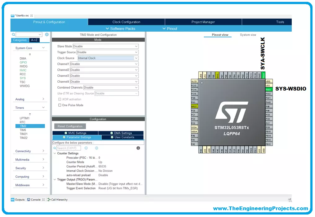
We will use for our examples STM32CubeIDE released by ST and completely free. STM32CubeIDE is a development tool and supports multi operative system (SO), which is part of the STM32Cube software ecosystem. STM32CubeIDE allows using a single platform to configure peripherals, to generate/compile/debug the code for STM32 microcontrollers and microprocessors. The framework used is Eclipse®/CDT, as tool-chain for the development is used GCC toolchain and GDB for the debugging.
To start the project, you must first select the MCU and then initialize and configure the peripherals the user wants to use. At this point, the initialization code is generated. At any time, the user can go back and change initializations and configurations, without affecting t ...
To become familiar with the world of microcontrollers it is necessary to have a development board (also known as a kit), which generally allows you to start working on it easily. Fortunately, the ST provides a wide portfolio of development boards. In this guide, we will describe and use the Nucleo board.
The Nucleo has been introduced a few years ago and its line is divided into three main groups:
Nucleo-32;
Nucleo-64;
Nucleo-144.
Nucleo-32 Development Board
The number of pins available, so the package, gives the name to the board: Nucleo-32 uses an LQFP-32 package; Nucleo-64 and LQFP-64; Nucleo-144 an LQFP-144. The Nucleo-64 was the first line introduced and counts 16 different boards.
The Nucleo boards have interesting advantages compa ...
In this guide, we will explain step by step to start programming on the STMicroelectronics (STM) platform, especially the STM32 family.
The term, "STM32" refers to a family of 32-bit microcontroller integrated circuits based on the ARM® Cortex®M processor. The architecture of these CPUs (Central Processing Unit) is ARM (Advanced Risk Machine) which is a particular family of Reduced Instruction Set Computing (RISC). RISC architecture differs from Complex Instruction Set Computing (CISC) for its simplicity that allows you to create processors capable of executing instruction sets with shorter times. Why use STM32? The advantages are many, and now we will list a part of them:
ST offers a wide portfolio of solutions depending on the developer's nee ...