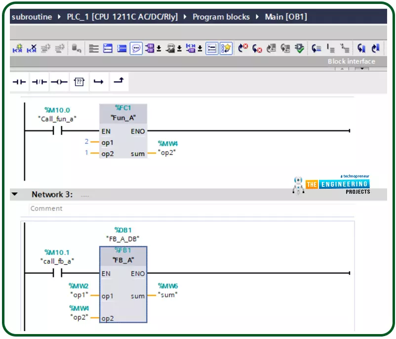
Hello friends, after completing that basic part of ladder logic programming, let us today go through one topic which is not essential to know to complete a PLC ladder program but it is important t have our code readable program and reusable pieces of code. That could happen by using what so-called a subroutine. So what is a subroutine? Well, it is a piece of code that includes a few rungs to perform specific tasks. that piece of code can be reused numerous times through the program when we need to call it for performing that task. That subroutine enables us to structure our code like building blocks so that the program will be readable very easy and also reusable later in other projects. The idea of dividing the program into routines to apply the divide and conquer technique is very crucia ...
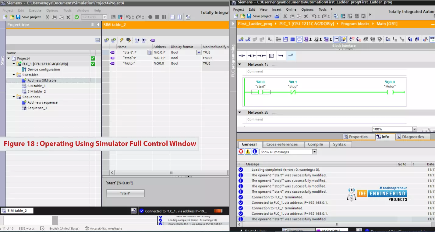
Hello friends, I hope you all are doing great. In today's tutorial, I am going to create the first Ladder Logic Program in PLC Simulator. It's 3rd tutorial in our Ladder Logic Programming Series. In our previous tutorial, we have installed PLC Simulator and now we can say our lab is ready to learn and practice. So let us get to work and get familiar with the ladder logic components.
After this article, you will have a complete understanding of PLC contact and coil including their types and possible causes. Because they are the building block of any rung of a ladder logic program. So let us start with ladder logic rung components.
Ladder Logic Contact/Input
In ladder logic programming, a contact represents the input of the system and it could b ...
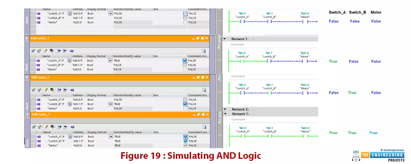
Hello friends, I hope you all are doing great. In today's tutorial, we are going to design logic gates in PLC Simulator. It's our 4th tutorial in Ladder Logic Programming Series. We come today to elaborate the logic gates with comprehensive details for their importance in PLC programming. you can consider logic gates as the building blocks of ladder logic programming. Like every time we start with telling what you guys are going to have after completing this session? For those who like to buy their time and calculate for feasibility, I’d like to say by completing this article, you are going to know everything about what types of logic gates, how they are designed and how they work, how you can translate the logic in your head into the logic gate a ...
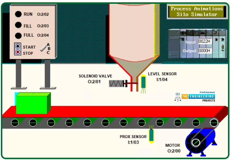
Hey guys! hope you are all very well. Today I come to you with a new process to learn, program, and simulate for practicing ladder logic more and more. The process we are going to implement today is a very common process that could be there in many many industries which is a silo process that aims to automate the process of filling containers or bottles with a liquid. Figure 1 shows the complete scene of the process including the system components, switches, indicators, sensors, and actuators that are integrated to make the system operate. Briefly and before going into deep details, let’s state what the system does and how it operates. Well! The system automatically fills the boxes that are traveling on the conveyor which is driven by a motor. They are filled with a liquid stored in the si ...
Hi friends, how are you doing? Today will integrate all of what we have learned so far in this series to build the first project based on ladder logic programming. Because we all are interested in industry, we pick one industrial project, Bottle Filling and Capping Projects, which is very common today. The problem we are going to solve today is bottle filling and capping. We have learned all basics of ladder logic including contacts and coils operation, logic gates, rising and falling edges, timers, and counters. So, today we will utilize all of these components to implement a complete ladder program of filling and capping problems.
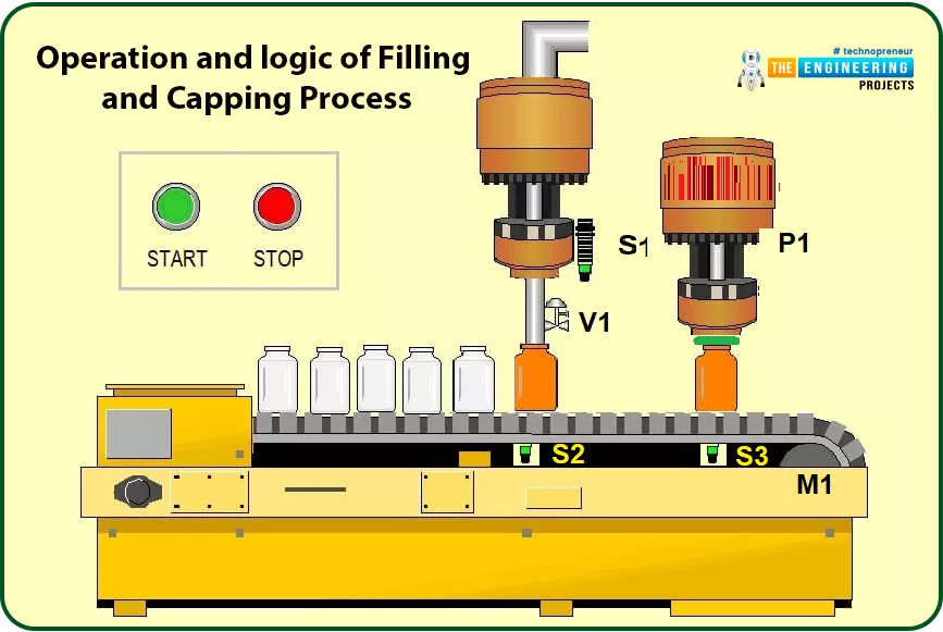
Operation and Logic of Bottle Filling and Capping Process
For simplifying the operation of the process of filling and capping, fig. 1 shows the process flow ...
Hi friends and hope you are all very well. Today, we are going to deal with one of the most important and common problems that would be there in everyday tasks in industry and its solution. The problem is the safety of equipment and operators by preventing the machine from running under specific conditions for realizing the safety of equipment and human as well. Not only does it fulfill safety but also it is for performing the designed sequence of operation. If there is a problem, then it should be the solution for it. the solution is what so-called “Interlock”. So, what is interlock? And why do we need it? And how we can design a good interlock? Well! We may find such concerns exist in two aspects which are safety and operation sequence. In the f ...
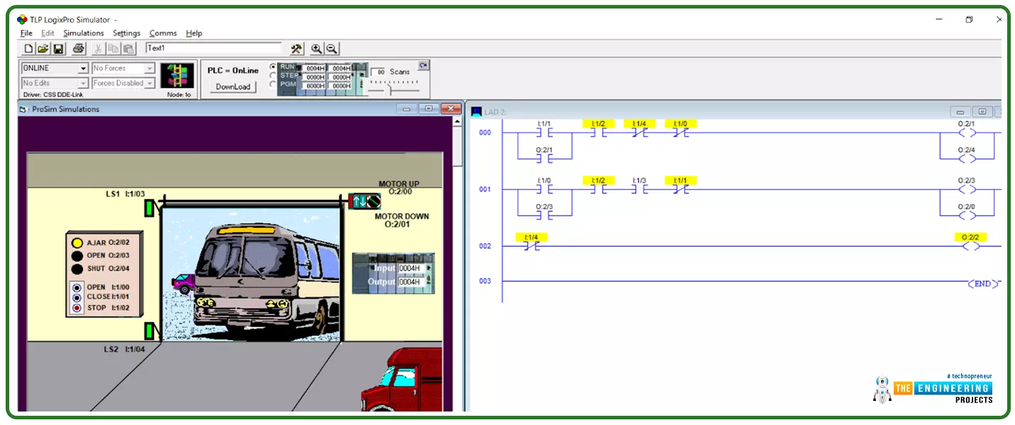
Hi Guys! hope you are doing great today! We come this time with a complete project to work out together starting from the point at which we sit with the client and receive the logical narratives that represent what they want to implement. We are going to start with a simple project this time and continue increasing the scale and complexity of the requirements through the incoming tutorials. The project we are going to implement today is one of the most common tasks that we can find in every place in our real life which is the control of the garage door. That could be found in private property or commercial buildings or public garages. Too many things need to be controlled in garage doors and several scenarios could come to your mind. However, take it as a rule of thumb that we design our p ...
Hello friends, How are you doing? Today, we have a very interesting topic of PLC ladder programming which is how to detect the transition between true and false and from low to high?. I know you are asking why do we need that? Well! Imagine my friends, we want to start a motor when the input signal state changes from high to low or from false to true. Let us give two examples to highlight the edge detection techniques. Good examples of using edge detection-based logic are timers and counters. In counters, they are energized to count up or down when a signal appears and the same for timers. Figure 1 shows the difference between using the edge to control a motor. In the top part, the motor is controlled by an input switch. the output is ON and OFF b ...
Hello friends, I hope you all are fine. Today, we are starting a new tutorials series on Ladder Logic Programming, used in PLC. It's our first tutorial in this series, so we are going to have a look at the detailed introduction to PLC and ladder logic. After welcoming every one of engineers, technicians, students, and hobbyists who have come to read this article willing to learn PLC programming, I would like to introduce one of the most used programming languages of PLC. The language we introduce here is a visualized language that connects and combines graphical symbols in logical flow same as the way we wire electrical circuits and that is the secret behind its simplicity not only in implementation but also in diagnosing problems.
Ladder Logic Pro ...
In the previous post Logical Gates in Ladder Logic for PLC, we had an overview of what is Ladder Logic programming and we have also implemented three basic Logical gates in Ladder Logic form. Today, we are gonna have a look at some complex Logical Gates in Ladder Logic for PLC. So, I hope till now you guys have basic knowledge of Ladder Logic and can implement complex logical gates in it. If you haven't read the previous post then must read because without that knowledge you won't understand this post.
In today's post we are gonna implement few complex logical gates. Its not gonna be much difficult if you have the basic concepts. I am just pointing out few important points here. While implementing any gate in ladder logic, always consider rung as ...