Hello friends! I hope you are all very well! I am so happy to meet you today to continue learning and practicing PLC ladder logic programming. In an earlier part, we already have gone through the very basic logic gates of “AND”. “OR”, and “NOT”. Today we are going to resume the simulation of logic gates. We have started and gone through simulating the basic logic gates which are “AND”, “OR”, and “NOT” as they are the most important basic logic gates by which we can form other logic gates. However, because the logic of large-scale projects is getting more and more complicating, a lot of time we have to use the other functions to do tasks faster. For example, we have shown in the logic gates article that, XOR can be used to compare two inputs and ch ...
Hi friends, today we are going to explore mathematical computations in ladder logic. Like in any programing language you should find logic and mathematic computations, here in PLC programming you often need to process the input data that is collected from reading analog devices like temperature, level, flow et cetera. Then you need to run some calculations on this data to derive some other variables for deciding to run or stop some device or even to determine analog output to output to analog device i.e. valve or actuators. In the following sections, we are going to explore the mathematical functions and their input operators and outputs as well. Then we will show how to utilize such functions in ladder logic with simple examples and as usual enjoy practicing them thanks to the PLC simula ...
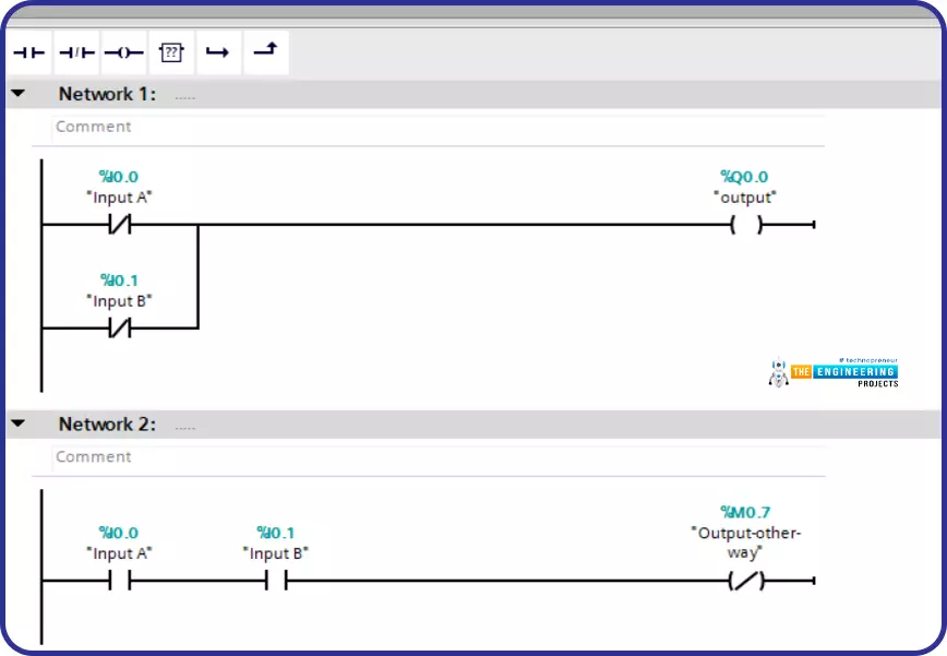
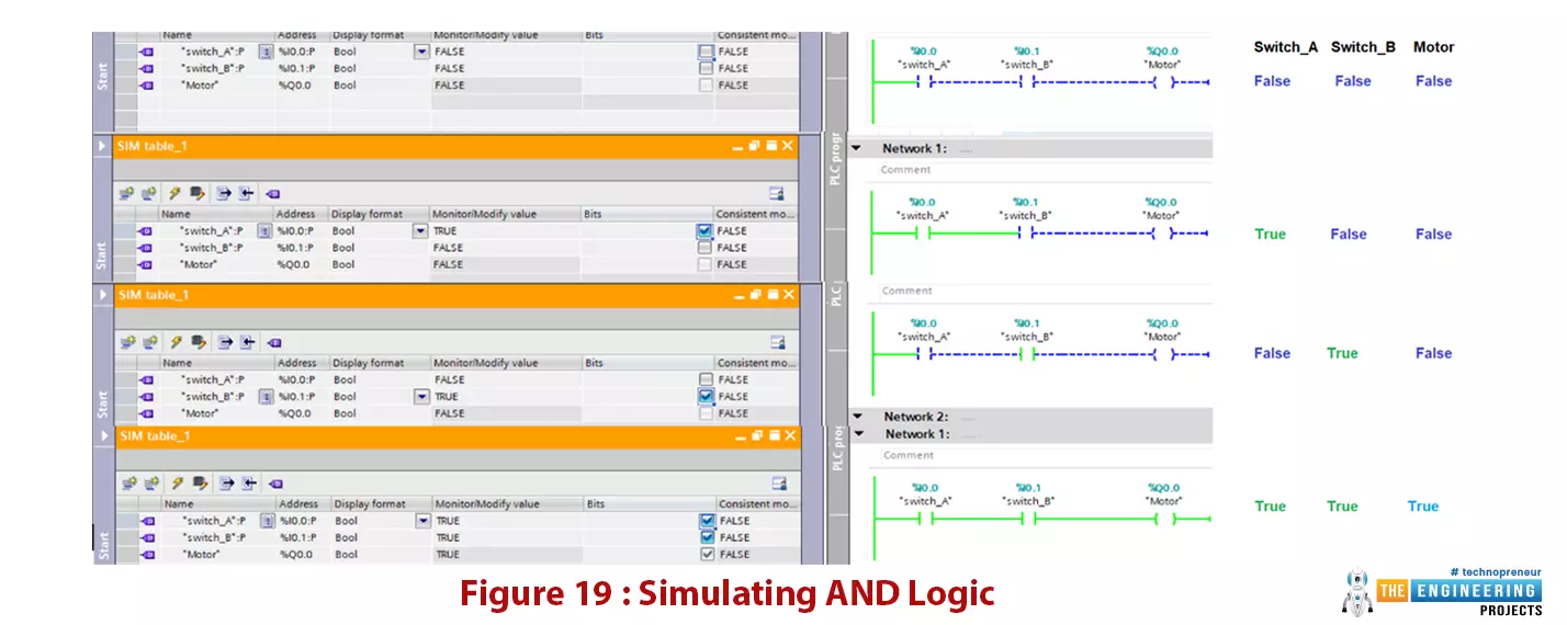
Hello friends, I hope you all are doing great. In today's tutorial, we are going to design logic gates in PLC Simulator. It's our 4th tutorial in Ladder Logic Programming Series. We come today to elaborate the logic gates with comprehensive details for their importance in PLC programming. you can consider logic gates as the building blocks of ladder logic programming. Like every time we start with telling what you guys are going to have after completing this session? For those who like to buy their time and calculate for feasibility, I’d like to say by completing this article, you are going to know everything about what types of logic gates, how they are designed and how they work, how you can translate the logic in your head into the logic gate a ...
Hi friends, today we are going to learn a good technique to run multi outputs in sequence. In another word, when we have some output that is repeatedly run in sequence. In the normal or conventional technique of programming we deal with them individually or one by one which takes more effort in programming and much space of memory. So instead we can use a new technique to trigger these outputs in sequence using one instruction which will save the effort of programming and space of memory. In this article, we are going to introduce how to implement sequencer output instruction. And practice some examples with the simulator as usual. Before starting the article, we need to mention that, some controllers like Allen Bradley have sequencer output instruction and some has not like Siemens. So we ...
Hi friends and hope you are all very well. Today, we are going to deal with one of the most important and common problems that would be there in everyday tasks in industry and its solution. The problem is the safety of equipment and operators by preventing the machine from running under specific conditions for realizing the safety of equipment and human as well. Not only does it fulfill safety but also it is for performing the designed sequence of operation. If there is a problem, then it should be the solution for it. the solution is what so-called “Interlock”. So, what is interlock? And why do we need it? And how we can design a good interlock? Well! We may find such concerns exist in two aspects which are safety and operation sequence. In the f ...
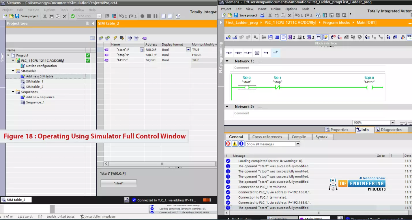
Hello friends, I hope you all are doing great. In today's tutorial, I am going to create the first Ladder Logic Program in PLC Simulator. It's 3rd tutorial in our Ladder Logic Programming Series. In our previous tutorial, we have installed PLC Simulator and now we can say our lab is ready to learn and practice. So let us get to work and get familiar with the ladder logic components.
After this article, you will have a complete understanding of PLC contact and coil including their types and possible causes. Because they are the building block of any rung of a ladder logic program. So let us start with ladder logic rung components.
Ladder Logic Contact/Input
In ladder logic programming, a contact represents the input of the system and it could b ...
Hello friends, I hope you all are fine. Today, we are starting a new tutorials series on Ladder Logic Programming, used in PLC. It's our first tutorial in this series, so we are going to have a look at the detailed introduction to PLC and ladder logic. After welcoming every one of engineers, technicians, students, and hobbyists who have come to read this article willing to learn PLC programming, I would like to introduce one of the most used programming languages of PLC. The language we introduce here is a visualized language that connects and combines graphical symbols in logical flow same as the way we wire electrical circuits and that is the secret behind its simplicity not only in implementation but also in diagnosing problems.
Ladder Logic Pro ...
Introduction
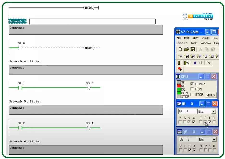
Hello friends, I hope you are doing very well. Today we are going to learn and practice the master control reset (MCR)! So what is that MCR? Well! This is a tool you might use to control a group of devices with one push button for performing fast emergency responses with one click for a group of devices in one zone. In another word, you divide the program into zones and put this zone between a master control to control their operation as one unit by one contact. This technique is useful for applying emergence stops and also protecting some equipment by applying a safety restriction to not operate when that condition is in effect.
The concept of the master control reset (MCR)
Figure 1 shows the master control relay in a ladder logic showing a couple of rungs between the ma ...
Hello friends, How are you doing? Today, we have a very interesting topic of PLC ladder programming which is how to detect the transition between true and false and from low to high?. I know you are asking why do we need that? Well! Imagine my friends, we want to start a motor when the input signal state changes from high to low or from false to true. Let us give two examples to highlight the edge detection techniques. Good examples of using edge detection-based logic are timers and counters. In counters, they are energized to count up or down when a signal appears and the same for timers. Figure 1 shows the difference between using the edge to control a motor. In the top part, the motor is controlled by an input switch. the output is ON and OFF b ...
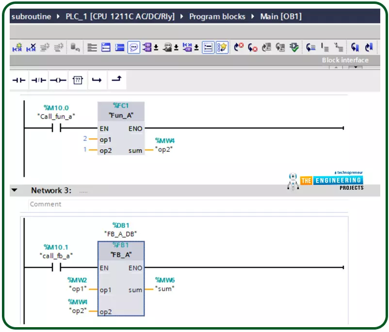
Hello friends, after completing that basic part of ladder logic programming, let us today go through one topic which is not essential to know to complete a PLC ladder program but it is important t have our code readable program and reusable pieces of code. That could happen by using what so-called a subroutine. So what is a subroutine? Well, it is a piece of code that includes a few rungs to perform specific tasks. that piece of code can be reused numerous times through the program when we need to call it for performing that task. That subroutine enables us to structure our code like building blocks so that the program will be readable very easy and also reusable later in other projects. The idea of dividing the program into routines to apply the divide and conquer technique is very crucia ...