


Introduction to TIP35


Introduction to TIP35
- It is a reliable silicon NPN transistor that is projected to use in common persistence amplification and swapping capitulations. It is existing in TO-247 that is no more used by most fabricators.
- This amplifier does not privilege to be 'state of the art' and in statistic the base enterprise times back to the initial 1970s. It is a modest amplifier to construct, usages normally accessible fragments and is constant and consistent.
- The scheme contained is a small adjustment of an amplifier which intended numerous ages back, of which hundreds were constructed.
- This transistor catches wide use in Power Swap structures like inverters, and output stages of audile amplifiers where they are associated in push-pull with a matching power transistor type.
- Whenever it is used in an audio amplifier arrangement, it is practical to initiative the power transistor from a pre-amplifier stage as maximum power transistors have a slight gain of current.
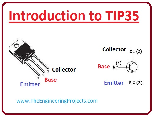
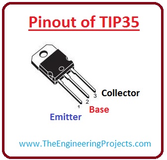
Pinout of TIP35
- These are the pinout of TIP35 which is well-defined underneath.
-
Lest see a diagram of the pinout.Pin# Type Parameters Pin#1 Emitter The emitter is for an outdoor motion of current. Pin#2 Base The base achieves the biasing of the transistor. It impulses the state of the transistor. Pin#3 Collector The collector is for the current inner drive. It is linked to the load.
Features of TIP35
- These are the main features of TIP35.
- It is offered in covering the type of TO-247.
- This fits in NPN transistors.
- The voltage put on at collector and emitter is 40 volts.
- The voltage at collector and base points is 40 volts.
- The voltage at emitter and base is five volts.
- This transistor devours 25-ampere current at the collector.
- The power forbearance at the collector point is 125 watts.
- Its gain is about 15 to 75.
- Its switching frequency is 3 Mhz.
- Its functioning and stowage joining temperature range are -65 to +150°C.
- This transistor is free from Lead (Pb).

Maximum Ratings of TIP35
| Symbols | Ratings | Parameters |
| VCEO | 60V | It is the voltage crosswise collector and emitter. |
| VCB | 60 V | It is the voltage crosswise collector and emitter. |
| VEB | 5.0 V | It is the voltage across emitter and base. |
| IC | 25 V | It is the current at the collector. |
| IB | 5.0 A | It is the value of current at the base point. |
| PD | 125 A | It is the entire Power Indulgence at T = 25 C overhead 25 C. |
| TJ, Tstg | -65 to +150 | Working and Storing Connection Temperature Choice |
| ESB | 90 | It is the unclamped Inductive Load. |
Electrical Characteristics
| Symbols | Ratings | Parameters |
| VCEO | 60V | These are C-E Supportive Voltage (IC = 30 mA, IB = 0) |
| ICEO | 1mA | It is the collector and emitter Cut-off Current. (VCE = 30 V). |
| ICES | 0.7mA | It is the collector and emitter Cut-off Current. |
| IEBO | 1 mA | It is the emitter and base Cut off Current. |
| hFE | 25 15 | It is the DC current gain. (IC = 1.5 A, VCE = 15 V) (IC = 4 A, VCE = 4 V) |
| VCE | 1.8 4.0 | These are emitter and collector saturation voltage. (IC = 15 A, VCE = 1.5 V) (IC = 25 A, VCE = 5 V) |
| VBE | 2V 4V | These are the Collector-Emitter Saturation Voltage. (IC = 15 A, IB = 4 A) (IC = 25 A, IB = 4 A) |
| ft | 3V | It is the current gain-bandwidth product. |
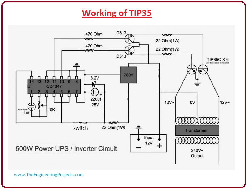
Working of TIP35
- Now we read about its working with a circuit diagram.
- In this circuit, I am going to show you 500W power inverter circuitry which using TIP35.
- In this circuit diagram, there is merely one adjustable resistance which is for changing the frequency of 240 AC output current.It is finest to use a frequency meter to regulate this frequency of 50HZ to 60HZ according to your requisite.Please avoid giving power any instrument by an inverter before changing the frequency according to your instrument. Otherwise, it will damage your device.
- For further understanding, let's see the circuit diagram.

Applications of TIP35
- These are specific applications of TIP35.
- It is cooperative obstinacy transistor it can be used in different industrial schemes.
- It is used as an audio Amplifier.
×
![]()


