using System;
using System.Drawing;
using System.Windows.Forms;

namespace TEPNet
{
    public partial class Form1 : Form
    {
        public Form1()
        {
            InitializeComponent();

        }

        private void button1_Click(object sender, EventArgs e)
        {
            checkedListBox1.Items.Add("TEP 1");
            checkedListBox1.Items.Add("TEP 2");
            checkedListBox1.Items.Add("TEP 3");
            checkedListBox1.Items.Add("TEP 4");
        }
    }
}
We have used the button. When user will click the button, C# Checked ListBox values appears. It depends on your logic that how you wanted to process the codes. I have used the button if you don't want to use the button you can simply copy the code after the InitializeComponent function. It will generate the following output when a button is clicked.
using System;
using System.Drawing;
using System.Windows.Forms;

namespace TEPNet
{
    public partial class Form1 : Form
    {
        public Form1()
        {
            InitializeComponent();

        }

        private void button1_Click(object sender, EventArgs e)
        {
            checkedListBox1.Items.Add("TEP 1", CheckState.Checked);
            checkedListBox1.Items.Add("TEP 2", CheckState.Indeterminate);
            checkedListBox1.Items.Add("TEP 3", CheckState.Unchecked);
            checkedListBox1.Items.Add("TEP 4");
        }
    }
}
We don't use the CheckState for the 4th item because by default it's unchecked. If you will execute the code, you observed that Check will be marked, Indeterminate is Check but can't edit and uncheck is unmarked. If you can't understand then the below image will the exact output of the above code.
using System;
using System.Drawing;
using System.Windows.Forms;

namespace TEPNet
{
    public partial class Form1 : Form
    {
        public Form1()
        {
            InitializeComponent();
            checkedListBox1.BackColor = Color.AliceBlue;
            checkedListBox1.Items.Add("TEP 1");
            checkedListBox1.Items.Add("TEP 2");
            checkedListBox1.Items.Add("TEP 3");
            checkedListBox1.Items.Add("TEP 4");
        }


    }
}
If you are wanted to change the foreground color or color of the font, then you have to use the ForeColor property to set the colors. We will be used the Color property to set the value of color which is assigned to the foreColor. In the following code, we have used BlueViolet color and set it for the foreground or for the font.
using System;
using System.Drawing;
using System.Windows.Forms;

namespace TEPNet
{
    public partial class Form1 : Form
    {
        public Form1()
        {
            InitializeComponent();
            checkedListBox1.ForeColor = Color.BlueViolet;
            checkedListBox1.Items.Add("TEP 1");
            checkedListBox1.Items.Add("TEP 2");
            checkedListBox1.Items.Add("TEP 3");
            checkedListBox1.Items.Add("TEP 4");
        }


    }
}
If you are wanted to change the font size, then you have to used to set the font property. We have to call the font constructor and passed two parameters. The first parameter is Font.FontFamily and the second parameter is the size of the font. In the following code, you can observe that how we changed the font size for Checked ListBox. The first parameter is the prototype and the second parameter is the font style property.
using System;
using System.Drawing;
using System.Windows.Forms;

namespace TEPNet
{
    public partial class Form1 : Form
    {
        public Form1()
        {
            InitializeComponent();
            checkedListBox1.Font = new Font(Font.FontFamily, 12);
            checkedListBox1.Items.Add("TEP 1");
            checkedListBox1.Items.Add("TEP 2");
            checkedListBox1.Items.Add("TEP 3");
            checkedListBox1.Items.Add("TEP 4");
        }


    }
}
If you are wanted to change the text style into italic, then you have to use the FontStyle property. We have to use the font constructor and passed two parameters. The first parameter is the prototype and the second one is the FontStyle.Value which is set to Italic in the following code. We have passed the CheckedListBox1.Font as the prototype parameter.
using System;
using System.Drawing;
using System.Windows.Forms;

namespace TEPNet
{
    public partial class Form1 : Form
    {
        public Form1()
        {
            InitializeComponent();
            checkedListBox1.Font = new Font(checkedListBox1.Font, FontStyle.Italic);
            checkedListBox1.Items.Add("TEP 1");
            checkedListBox1.Items.Add("TEP 2");
            checkedListBox1.Items.Add("TEP 3");
            checkedListBox1.Items.Add("TEP 4");
        }
    }
}
If you are wanted to bold the text, then you have to use the font constructor and passed the Font style as the bold. In the following code, we have changed the text of checkedListBox items to bold.
using System;
using System.Drawing;
using System.Windows.Forms;

namespace TEPNet
{
    public partial class Form1 : Form
    {
        public Form1()
        {
            InitializeComponent();
            checkedListBox1.Font = new Font(checkedListBox1.Font, FontStyle.Bold);
            checkedListBox1.Items.Add("TEP 1");
            checkedListBox1.Items.Add("TEP 2");
            checkedListBox1.Items.Add("TEP 3");
            checkedListBox1.Items.Add("TEP 4");
        }


    }
}
If you are wanted to change the font family style then you have to use the font constructor and passed the font family name and size as the parameter. The first parameter is the name of font family and the second parameter is the font size. In the following code, we have used the "Times New Roman" and the size as 20.
using System;
using System.Drawing;
using System.Windows.Forms;

namespace TEPNet
{
    public partial class Form1 : Form
    {
        public Form1()
        {
            InitializeComponent();
            checkedListBox1.Font = new Font("Times New Roman",20);
            checkedListBox1.Items.Add("TEP 1");
            checkedListBox1.Items.Add("TEP 2");
            checkedListBox1.Items.Add("TEP 3");
            checkedListBox1.Items.Add("TEP 4");
        }


    }
}
If you are wanted to check that what the value you have selected, then you have to use the SelectedItem. In the following code, I have used the button and message box to show the selected item value. If you will execute the code, then you have to select the items first then click the button and it returns the selected item value in the message box.
using System;
using System.Drawing;
using System.Windows.Forms;

namespace TEPNet
{
    public partial class Form1 : Form
    {
        public Form1()
        {
            InitializeComponent();
            checkedListBox1.Items.Add("TEP 1");
            checkedListBox1.Items.Add("TEP 2");
            checkedListBox1.Items.Add("TEP 3");
            checkedListBox1.Items.Add("TEP 4");
        }

        private void button1_Click(object sender, EventArgs e)
        {
            MessageBox.Show(checkedListBox1.SelectedItem.ToString());
        }


    }
}
If you are wanted to verify that, which items are marked or check, then you have to use the foreach loop. In the following code, we have used the foreach loop to get the value from checkedListBox1.CheckedItems into an object-based variable which is itemCheck. Then we have to use message box to show the value of itemCheck in each step of a loop by converting the object type value into a string by calling the ToSting method.
using System;
using System.Drawing;
using System.Windows.Forms;

namespace TEPNet
{
    public partial class Form1 : Form
    {
        public Form1()
        {
            InitializeComponent();
            checkedListBox1.Items.Add("TEP 1");
            checkedListBox1.Items.Add("TEP 2");
            checkedListBox1.Items.Add("TEP 3");
            checkedListBox1.Items.Add("TEP 4");
        }

        private void button1_Click(object sender, EventArgs e)
        {
         foreach (object itemChecked in checkedListBox1.CheckedItems)
            {
                MessageBox.Show(itemChecked.ToString());
            }
        }
    }
}
If you are wanted to change the border style of Checked ListBox, then you have to use the BorderStyle property and set the style according to your need. There are three styles which you can apply, all those styles are mention in the following code. You can check them one by one, if you will execute all of these styles at once then only the last one is getting executed and other above will get ignored by the compiler.
checkedListBox1.BorderStyle = BorderStyle.Fixed3D;
checkedListBox1.BorderStyle = BorderStyle.FixedSingle;
checkedListBox1.BorderStyle = BorderStyle.None;
using System;
using System.Drawing;
using System.Windows.Forms;

namespace TEPNet
{
    public partial class Form1 : Form
    {
        public Form1()
        {
            InitializeComponent();
            checkedListBox1.Items.Add("TEP 1");
            checkedListBox1.Items.Add("TEP 2");
            checkedListBox1.Items.Add("TEP 3");
            checkedListBox1.Items.Add("TEP 4");
        }


        private void checkedListBox1_Click(object sender, EventArgs e)
 {
 MessageBox.Show("You have Clicked !!");
 }
    }
}
An output of the above code is given in the following image. You can perform any functionality as you required. For the demonstration purpose just used the message box to reflect any action.
using System;
using System.Drawing;
using System.Windows.Forms;

namespace TEPNet
{
    public partial class Form1 : Form
    {
        public Form1()
        {
            InitializeComponent();
            checkedListBox1.Items.Add("TEP 1");
            checkedListBox1.Items.Add("TEP 2");
            checkedListBox1.Items.Add("TEP 3");
            checkedListBox1.Items.Add("TEP 4");
        }

        private void checkedListBox1_MouseHover(object sender, EventArgs e)
        {
            MessageBox.Show("Mouse is Hover !!");
        }
    }
}
The above function is builtin and if you want to set the user define function then you can set by your own in the event property. You can perform any kind of functionality, we have used the message box, if you wanted to change anything then you can change such as the color, font family, and size of the text. In the following image, you can view the output of the above code.
using System;
using System.Drawing;
using System.Windows.Forms;

namespace TEPNet
{
    public partial class Form1 : Form
    {
        public Form1()
        {
            InitializeComponent();
        }
        private void button1_Click(object sender, EventArgs e)
        {
            checkedListBox1.Items.Add("TEP 1");
            checkedListBox1.Items.Add("TEP 2");
            checkedListBox1.Items.Add("TEP 3");
            checkedListBox1.Items.Add("TEP 4");
        }
        private void checkedListBox1_MouseLeave(object sender, EventArgs e)
        {
            MessageBox.Show("Mouse is Leave !!");
        }
    }
}
MouseLeave is the default function which you can use after the name of CheckedListBox object name. You can set any user define function also as the alternative of the default function. When you will click the button it will be inserted the values in the CheckedListBox and when you hover the mouse cursor and leave the boundaries it will be executed the MouseLeave method. If you will not click the button, in this case, MousLeave method worked also. The following image is the screenshot of output.
using System;
using System.Drawing;
using System.Windows.Forms;

namespace TEPNet
{
    public partial class Form1 : Form
    {
        public Form1()
        {
            InitializeComponent();
            checkedListBox1.Items.Add("TEP 1");
            checkedListBox1.Items.Add("TEP 2");
            checkedListBox1.Items.Add("TEP 3");
            checkedListBox1.Items.Add("TEP 4");

        }

        private void button1_Click(object sender, EventArgs e)
        {
            checkedListBox1.BackColor = Color.AliceBlue;
        }

        private void checkedListBox1_BackColorChanged(object sender, EventArgs e)
        {
            MessageBox.Show("BackColor Is Changed !");
        }
    }
}
In the above code, we have inserted the values in CheckedListBox during the form initialization phase. Then we have declared the Alice Blue as the backColor of the CheckedListBox within button click event. When user will click on the button, a background color of checkedListBox is get changed and the backColorChanged event gets executed. In the following image, you can preview the output of the above code.
using System;
using System.Drawing;
using System.Windows.Forms;

namespace TEPNet
{
    public partial class Form1 : Form
    {
        public Form1()
        {
            InitializeComponent();
            checkedListBox1.Items.Add("TEP 1");
            checkedListBox1.Items.Add("TEP 2");
            checkedListBox1.Items.Add("TEP 3");
            checkedListBox1.Items.Add("TEP 4");

        }

        private void button1_Click(object sender, EventArgs e)
        {
            checkedListBox1.ForeColor = Color.Red;
        }

        private void checkedListBox1_ForeColorChanged(object sender, EventArgs e)
        {
            MessageBox.Show("ForeColor Is Changed !");
        }
    }
}
In the above code, we have inserted the demo values in the initialization phase of the form. Then we have used the button click event to change the foreColor of the CheckedListBox. Then we have used message box as the functionality which is performed when ForeColor is changed. In the following image, you can observe the output of the above code.
using System;
using System.Drawing;
using System.Windows.Forms;

namespace TEPNet
{
    public partial class Form1 : Form
    {
        public Form1()
        {
            InitializeComponent();
            checkedListBox1.Items.Add("TEP 1");
            checkedListBox1.Items.Add("TEP 2");
            checkedListBox1.Items.Add("TEP 3");
            checkedListBox1.Items.Add("TEP 4");

        }

        private void button1_Click(object sender, EventArgs e)
        {
            checkedListBox1.Font = new Font(Font.FontFamily, 12);
        }

        private void checkedListBox1_FontChanged(object sender, EventArgs e)
        {
            MessageBox.Show("Font Is Changed !");
        }
    }
}
If you want to execute above code in your compiler, then you have to drag the button and CheckedListBox. Then activate the button click and FontChanged Event. Then copy paste the above code into a compiler and you will be able to execute the program. Below is the output image of above code.
using System;
using System.Drawing;
using System.Windows.Forms;
namespace TEP
{
public partial class Form1 : Form
{
public Form1()
{
InitializeComponent();
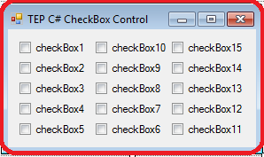
checkBox1.Text = "TEP CheckBox1";
checkBox2.Text = "TEP CheckBox2";
checkBox3.Text = "TEP CheckBox3";
checkBox4.Text = "TEP CheckBox4";
checkBox5.Text = "TEP CheckBox5";
}
}
}
In the above code, you have observed that we have used text property right after initializecomponent() method. Because we are setting checkbox text dynamically and it will only happen when we will declare this code in the initialization phase of a desktop application. In the following image, you can observe the output of above code.
using System;
using System.Drawing;
using System.Windows.Forms;

namespace TEP
{
    public partial class Form1 : Form
    {
        public Form1()
        {
            InitializeComponent();
            checkBox1.Checked = true;
            checkBox2.Checked = true;
            checkBox3.Checked = true;
        }
    }
}
In the above code, we only marked check first three checkboxes. By this, you can mark check and uncheck the checkboxes by default. In the following image, you can observe the output of above code.
using System;
using System.Drawing;
using System.Windows.Forms;

namespace TEP
{
    public partial class Form1 : Form
    {
        public Form1()
        {
            InitializeComponent();
            checkBox1.BackColor = Color.AliceBlue;
            checkBox2.BackColor = Color.Beige;
            checkBox3.BackColor = Color.BlueViolet;

            checkBox4.BackColor = Color.BurlyWood;
            checkBox5.BackColor = Color.DarkBlue;
            checkBox6.BackColor = Color.DarkOrange;

            checkBox7.BackColor = Color.DeepSkyBlue;
            checkBox8.BackColor = Color.Gainsboro;
            checkBox9.BackColor = Color.LawnGreen;
            checkBox10.BackColor = Color.LightSeaGreen;
        }
    }
}
There are ten checkboxes in the above code, each checkbox has a unique color. Color combination is the major part of designing phase. The client basically focused on the front end of the desktop app that's why coloring matters a lot. In the following image, you can be observed that what right color mean to the eye and whats the wrong color means to an eye, its the output of above code.
using System;
using System.Drawing;
using System.Windows.Forms;

namespace TEP
{
    public partial class Form1 : Form
    {
        public Form1()
        {
            InitializeComponent();
            checkBox1.ForeColor = Color.AliceBlue;
            checkBox2.ForeColor = Color.Beige;
            checkBox3.ForeColor = Color.BlueViolet;

            checkBox4.ForeColor = Color.BurlyWood;
            checkBox5.ForeColor = Color.DarkBlue;
            checkBox6.ForeColor = Color.DarkOrange;

            checkBox7.ForeColor = Color.DeepSkyBlue;
            checkBox8.ForeColor = Color.Gainsboro;
            checkBox9.ForeColor = Color.LawnGreen;
            checkBox10.ForeColor = Color.LightSeaGreen;
        }
    }
}
In the above code, some colors are very light in shade and some are dark. We can't judge the color by their names. Because there are many colors to be used. If you want to select any color then you can to try all the color first. In the following image, you can observe the output of the above code. Some colors are the light that's why you can't clearly saw the output.
using System;
using System.Drawing;
using System.Windows.Forms;

namespace TEP
{
    public partial class Form1 : Form
    {
        public Form1()
        {
            InitializeComponent();
            checkBox1.Font = new Font(Font.FontFamily, 5);
            checkBox2.Font = new Font(Font.FontFamily, 6);
            checkBox3.Font = new Font(Font.FontFamily, 7);

            checkBox4.Font = new Font(Font.FontFamily, 8);
            checkBox5.Font = new Font(Font.FontFamily, 9);
            checkBox6.Font = new Font(Font.FontFamily, 10);

            checkBox7.Font = new Font(Font.FontFamily, 11);
            checkBox8.Font = new Font(Font.FontFamily, 12);
            checkBox9.Font = new Font(Font.FontFamily, 13);
            checkBox10.Font = new Font(Font.FontFamily, 14);
        }
    }
}
We have used Font.FontFamily as the prototype and integer value as the size of the font. You can also change the font family by using the font constructor. In the following image, you can observe the output of above code. You will also observe that as much integer value is small the size gets decreased and as much the value is incremented the size get increased.
using System;
using System.Drawing;
using System.Windows.Forms;

namespace TEP
{
    public partial class Form1 : Form
    {
        public Form1()
        {
            InitializeComponent();

            checkBox1.Font = new Font("Times New Roman", 11);
            checkBox2.Font = new Font("Century", 11);
            checkBox3.Font = new Font("Arial", 11);
            checkBox4.Font = new Font("Comic Sans MS", 11);
            checkBox5.Font = new Font("Copperplate Gothic Light", 11);
            checkBox6.Font = new Font("Georgia", 11);
            checkBox7.Font = new Font("Impact", 11);
            checkBox8.Font = new Font("Lucida Console", 11);
        }
    }
}
All the above font family names are the default fonts which are available in the windows. If you want to use the special kind of font then you have to install that first before use. You have also mentioned the size along with the font family name. In the following image, you can be observed the output of the above code, and what font effects on the desktop application.
using System;
using System.Drawing;
using System.Windows.Forms;

namespace TEP
{
    public partial class Form1 : Form
    {
        public Form1()
        {
            InitializeComponent();


        }

        private void button1_Click(object sender, EventArgs e)
        {
            if (checkBox1.Checked == true)
            {
                MessageBox.Show(checkBox1.Text);
            }
            if (checkBox2.Checked == true)
            {
                MessageBox.Show(checkBox2.Text);
            }
            if (checkBox3.Checked == true)
            {
                MessageBox.Show(checkBox3.Text);
            }
            if (checkBox4.Checked == true)
            {
                MessageBox.Show(checkBox4.Text);
            }
            if (checkBox5.Checked == true)
            {
                MessageBox.Show(checkBox5.Text);
            }
            if (checkBox6.Checked == true)
            {
                MessageBox.Show(checkBox6.Text);
            }
            if (checkBox7.Checked == true)
            {
                MessageBox.Show(checkBox7.Text);
            }
            if (checkBox8.Checked == true)
            {
                MessageBox.Show(checkBox8.Text);
            }
            if (checkBox9.Checked == true)
            {
                MessageBox.Show(checkBox9.Text);
            }
            if (checkBox10.Checked == true)
            {
                MessageBox.Show(checkBox10.Text);
            }
        }
    }
}
You can observe the output of the above code in the following image. In which we have to click the button after the selection of checkbox3 and it returns the message box with its name.
using System;
using System.Drawing;
using System.Windows.Forms;

namespace TEP
{
    public partial class Form1 : Form
    {
        public Form1()
        {
            InitializeComponent();
            checkBox1.Image = Image.FromFile("C:\\Users\\Jade\\Pictures\\brownImage.jpg");
        }
    }
}
using System;
using System.Drawing;
using System.Windows.Forms;

namespace TEP
{
    public partial class Form1 : Form
    {
        public Form1()
        {
            InitializeComponent();
        }

        private void button1_Click(object sender, EventArgs e)
        {
            checkBox1.BackColor = Color.AliceBlue;
        }

        private void checkBox1_BackColorChanged(object sender, EventArgs e)
        {
            MessageBox.Show("BackColorChanged Executed!");
        }
    }
}
We have used AliceBlue color for the background. You can use other colors too, there are varieties of colors are available. In the following image, you can observe the output of above code. We have executed just message box when the color changed, you can perform any kind of functionality.
using System;
using System.Drawing;
using System.Windows.Forms;

namespace TEP
{
    public partial class Form1 : Form
    {
        public Form1()
        {
            InitializeComponent();

        }

        private void checkBox1_CheckedChanged(object sender, EventArgs e)
        {
            MessageBox.Show("CheckedChanged Executed!");
        }
    }
}
You have to create a CheckedChange event for each of the C# CheckBox. We have just created for the first checkBox. In the following image, you can observe that we only mark checked the first checkbox and it returns the message popup.
using System;
using System.Drawing;
using System.Windows.Forms;

namespace TEP
{
    public partial class Form1 : Form
    {
        public Form1()
        {
            InitializeComponent();
        }

        private void checkBox1_Click(object sender, EventArgs e)
        {
            MessageBox.Show("Click Executed!");
        }
    }
}
In the above code, we just declare click event for checkbox1 only, if you will copy paste it multiple times and rename as checkbox2 and checkbox3 then it would not work. Because you have also assigned the event to the event property which is on the right bottom of visual studio. In the following image, you can be observed the output after execution of the code.
using System;
using System.Drawing;
using System.Windows.Forms;

namespace TEP
{
    public partial class Form1 : Form
    {
        public Form1()
        {
            InitializeComponent();


        }

        private void button1_Click(object sender, EventArgs e)
        {
            checkBox1.ForeColor = Color.AliceBlue;

        }

        private void checkBox1_ForeColorChanged(object sender, EventArgs e)
        {
            MessageBox.Show("ForeColorChanged Executed!");
        }
    }
}
When user will click the button, ForeColor of first C# CheckBox is get changed from Black to AliceBlue. After color get changed ForeColorChanged event get executed the return the message popup. In the following image, you can be observed the output that C# CheckBox1 foreColor gets changed.
using System;
using System.Drawing;
using System.Windows.Forms;

namespace TEP
{
    public partial class Form1 : Form
    {
        public Form1()
        {
            InitializeComponent();


        }

        private void checkBox1_MouseHover(object sender, EventArgs e)
        {
            checkBox1.ForeColor = Color.BlueViolet;
            MessageBox.Show("ForeColorChanged Executed!");
        }
    }
}
This is a quite good example to demonstrate the MouseHover event. When user will hover the mouse cursor on the CheckBox1 then ForeColor is get changed into Blue Violet. In the following image, you can get the main idea how it looks after the execution.
using System;
using System.Drawing;
using System.Windows.Forms;

namespace strnull
{
    public partial class Form1 : Form
    {
        public Form1()
        {
            InitializeComponent();


        }

        private void checkBox1_MouseHover(object sender, EventArgs e)
        {
            checkBox1.ForeColor = Color.BlueViolet;

        }

        private void checkBox1_MouseLeave(object sender, EventArgs e)
        {
            checkBox1.ForeColor = Color.Black;

        }
    }
}
If you want to execute the above code, then you have to drag one checkbox on your windows form. Then add mouse leave and mouse hover event. Copy the above code and inserted into your compiler and executed. When you will hover the mouse on the checkbox1 its font color gets changed and when leaving the checkbox then fore color get to default.
using System;
using System.Drawing;
using System.Windows.Forms;

namespace TEP
{
    public partial class Form1 : Form
    {
        public Form1()
        {
            InitializeComponent();
        }

        private void button1_Click(object sender, EventArgs e)
        {
            checkBox1.Text = "Changed !";

        }

        private void checkBox1_TextChanged(object sender, EventArgs e)
        {
            MessageBox.Show("Text Changed !!");
        }
    }
}
For each checkbox, you have to declare the separate TextChanged event handler. In the above code, we declared it just for the checkbox1. So when the default text of checkbox1 is get changed, TextChanged event get raised. In the following image, you can be observed the output.
using System;
using System.Drawing;
using System.Windows.Forms;

namespace TEP
{
    public partial class Form1 : Form
    {
        public Form1()
        {
            InitializeComponent();
            radioButton5.Text = "TEP Code RB5";
            radioButton6.Text = "TEP Code RB6";
            radioButton7.Text = "TEP Code RB7";
            radioButton8.Text = "TEP Code RB8";
        }
    }
}
It depends on your ease, you can use the both method to set the name of radio buttons. For your better understanding, we have attached the screenshot of output along with the code.
using System;
using System.Drawing;
using System.Windows.Forms;

namespace TEP
{
    public partial class Form1 : Form
    {
        public Form1()
        {
            InitializeComponent();
            radioButton1.Checked = true;
        }
    }
}
If you will add more radio buttons checked true then the only last radio button will be checked. Because you can only be checked one radio button at the same time. In the following image, you can preview that only radio button1 is checked.
using System;
using System.Drawing;
using System.Windows.Forms;

namespace strnull
{
    public partial class Form1 : Form
    {
        public Form1()
        {
            InitializeComponent();
            radioButton1.BackColor = Color.AliceBlue;
            radioButton2.BackColor = Color.AntiqueWhite;
            radioButton3.BackColor = Color.Aqua;
            radioButton4.BackColor = Color.Aquamarine;
            radioButton5.BackColor = Color.Azure;
            radioButton6.BackColor = Color.Beige;
            radioButton7.BackColor = Color.Bisque;
            radioButton8.BackColor = Color.BlueViolet;
        }
    }
}
You must have to use the Color object to set any color. For the better understanding, we have taken the screenshot of output along with the code which is overriding the color properties.
using System;
using System.Drawing;
using System.Windows.Forms;

namespace TEP
{
    public partial class Form1 : Form
    {
        public Form1()
        {
            InitializeComponent();
            radioButton1.ForeColor = Color.YellowGreen;
            radioButton2.ForeColor = Color.Tomato;
            radioButton3.ForeColor = Color.Violet;
            radioButton4.ForeColor = Color.Turquoise;
            radioButton5.ForeColor = Color.SteelBlue;
            radioButton6.ForeColor = Color.Sienna;
            radioButton7.ForeColor = Color.SeaGreen;
            radioButton8.ForeColor = Color.BlueViolet;
        }
    }
}
We used the Color object to set the color. In the following image, you can observe that how the color changes the appearance and interface. By using the color schemes you can make eye attractive windows form and make easier for the user to identified usable features of your app.
using System;
using System.Drawing;
using System.Windows.Forms;

namespace TEP
{
    public partial class Form1 : Form
    {
        public Form1()
        {
            InitializeComponent();
            radioButton1.Font = new Font(Font.FontFamily,10);
            radioButton2.Font = new Font(Font.FontFamily, 11);
            radioButton3.Font = new Font(Font.FontFamily, 12);
            radioButton4.Font = new Font(Font.FontFamily, 13);
            radioButton5.Font = new Font(Font.FontFamily, 12);
            radioButton6.Font = new Font(Font.FontFamily, 11);
            radioButton7.Font = new Font(Font.FontFamily, 10);
            radioButton8.Font = new Font(Font.FontFamily, 9);
        }
    }
}
In the above code, we have used a different size for each RadioButton. The first four RadioButton size is increased and other four RadioButton size get a decrease. In the following image, you can observe the size of radio buttons.
using System;
using System.Drawing;
using System.Windows.Forms;

namespace TEP
{
    public partial class Form1 : Form
    {
        public Form1()
        {
            InitializeComponent();
            radioButton1.Font = new Font("Times New Roman", 11);
            radioButton2.Font = new Font("Century", 11);
            radioButton3.Font = new Font("Arial", 11);
            radioButton4.Font = new Font("Comic Sans MS", 11);
            radioButton5.Font = new Font("Copperplate Gothic Light", 11);
            radioButton6.Font = new Font("Georgia", 11);
            radioButton7.Font = new Font("Impact", 11);
            radioButton8.Font = new Font("Lucida Console", 11);

        }
    }
}
All the above-used fonts are the default font which is available in Windows. If you don't know which font you have to used then used Google Font. It will help you to select the best font for your desktop application. In the following image, you can observe how font changes the appearance of your desktop application.
using System;
using System.Drawing;
using System.Windows.Forms;

namespace TEP
{
    public partial class Form1 : Form
    {
        public Form1()
        {
            InitializeComponent();
        }
        private void button1_Click(object sender, EventArgs e)
        {
            if (radioButton1.Checked == true)
            {
                MessageBox.Show(radioButton1.Text);
            }
            else
            if (radioButton2.Checked == true)
            {
                MessageBox.Show(radioButton2.Text);
            }
            else
            if (radioButton3.Checked == true)
            {
                MessageBox.Show(radioButton3.Text);
            }
            else
            if (radioButton4.Checked == true)
            {
                MessageBox.Show(radioButton4.Text);
            }
            else
            if (radioButton5.Checked == true)
            {
                MessageBox.Show(radioButton5.Text);
            }
            else
            if (radioButton6.Checked == true)
            {
                MessageBox.Show(radioButton6.Text);
            }
            else
            if (radioButton7.Checked == true)
            {
                MessageBox.Show(radioButton7.Text);
            }
            else
            if (radioButton8.Checked == true)
            {
                MessageBox.Show(radioButton8.Text);
            }
        }
    }
}
If you want to try the above code in your own compiler, then you have to add button click event first then you can execute the above code. It will allow you to select an option, and when you press the button it will generate the popup message and return the value of selected radio button. In the following image, you can observe the output of the above code.
using System;
using System.Drawing;
using System.Windows.Forms;

namespace TEP
{
    public partial class Form1 : Form
    {
        public Form1()
        {
            InitializeComponent();
            radioButton1.Image = Image.FromFile("C:\\Users\\Jade\\Pictures\\brownImage.jpg");
        }
    }
}
| First Method | Second Method |
|---|---|
using System;
using System.Drawing;
using System.Windows.Forms;

namespace strnull
{
    public partial class Form1 : Form
    {
        public Form1()
        {
            InitializeComponent();

        }

        private void button1_Click(object sender, EventArgs e)
        {
            radioButton1.BackColor = Color.AliceBlue;
        }

        private void radioButton1_BackColorChanged(object sender, EventArgs e)
        {
            MessageBox.Show("BackColor is changed to " + radioButton1.BackColor.ToString());
        }

    }
}
In the above code, when the background color of the radio button is changed. Message prompt with the name of color which is set as the background. In the following image, you can observe the output of the above code.
using System;
using System.Drawing;
using System.Windows.Forms;

namespace TEP
{
    public partial class Form1 : Form
    {
        public Form1()
        {
            InitializeComponent();

        }

        private void radioButton1_CheckedChanged(object sender, EventArgs e)
        {
            MessageBox.Show("Option changed.");
        }

    }
}
In the above code, we have used two radio button. Whenever you will change the radio buttons value or option CheckedChanged event gets executed. In the below image you can observe the output
using System;
using System.Drawing;
using System.Windows.Forms;

namespace TEP
{
    public partial class Form1 : Form
    {
        public Form1()
        {
            InitializeComponent();


        }

        private void radioButton1_Click(object sender, EventArgs e)
        {
            MessageBox.Show("You Clicked!");
        }

    }
}
In the above code, we have used two radio buttons and just added the click event to the first radio button. If you will click the radio button1 then you will observe the popup message but if you clicked in the radio button2 then nothing will happen except that radio button2 get selected. It's because we have added the Click event just for the radio button1. In the following image, you can observe the output of above code.
using System;
using System.Drawing;
using System.Windows.Forms;

namespace TEP
{
    public partial class Form1 : Form
    {
        public Form1()
        {
            InitializeComponent();


        }

        private void button1_Click(object sender, EventArgs e)
        {
            radioButton1.ForeColor = Color.BlueViolet;

        }


        private void radioButton1_ForeColorChanged(object sender, EventArgs e)
        {
            MessageBox.Show("ForeColor Is changed to " + radioButton1.ForeColor.ToString());
        }

    }
}
In the above code, we have set the ForeColor ti BlueViolet when user will click the button. Then ForeColorChanged Event executed and prompt the message which color is selected as the ForeColor. In the following image, you can observe the output of the above code.
using System;
using System.Drawing;
using System.Windows.Forms;

namespace TEP
{
    public partial class Form1 : Form
    {
        public Form1()
        {
            InitializeComponent();


        }

        private void radioButton1_MouseHover(object sender, EventArgs e)
        {
            MessageBox.Show("Mouse Hover to " + radioButton1.Text.ToString());
        }

    }
}
In the above code, we have set the prompt message when user will hover the first radio button. You can declare any kind of functionality which you want to perform. In the following Image, you can be observed the output.
using System;
using System.Drawing;
using System.Windows.Forms;

namespace strnull
{
    public partial class Form1 : Form
    {
        public Form1()
        {
            InitializeComponent();
        }

        private void radioButton1_MouseHover(object sender, EventArgs e)
        {
            MessageBox.Show("Mouse Hover to " + radioButton1.Text.ToString());
        }

        private void radioButton1_MouseLeave(object sender, EventArgs e)
        {
            MessageBox.Show("Mouse Left " + radioButton1.Text.ToString());
        }

    }
}
In the above code, you cab observed the MouseHover and MouseLeave both events. When user will hover the mouse a prompt message show that user is hover mouse cursor on radiobutton1 and when a user left the radiobutton1 boundaries its show prompt message again. In the below image you can observe the output of above code.
using System;
using System.Drawing;
using System.Windows.Forms;

namespace TEP
{
    public partial class Form1 : Form
    {
        public Form1()
        {
            InitializeComponent();

        }

        private void button1_Click(object sender, EventArgs e)
        {
            radioButton1.Text = "New Text";
        }

        private void radioButton1_TextChanged(object sender, EventArgs e)
        {
            MessageBox.Show("Radio Button Text changed to " + radioButton1.Text.ToString());
        }

    }
}
You can observe in the above code, there are two events. The button click event changed the text of radio button and TextChanged event get executed when text gets changed. In the following image, you can be observed the output. You also observed that when button event is executed radio button text doesn't change but the value is set to new text. After the execute of textChanged Event, it's get changed. It's because all the events have same priority or execution, so first events get executed then their effects applied.
Hello everyone, I hope you all are doing great. In today's tutorial, I am going to show you the advantages of Outsourcing Software Development. If you are a software engineer and also an Entrepreneur, then you must have heard about Outsourcing. You must have a look at this outstanding tutorial because they have quite clearly answered this question Why Outsourcing Software Development?
Technologies have evolved in an amazing way to leverage people and make their lives easy. The role of Artificial Intelligence in Software Development has revolutionized this industry. Nowadays, companies that survive in the market are the ones with a better understanding of their goals and work in a strategic way. You cannot adopt old ways to run your businesses and still claim a top position in the market.
To make your business run successfully, you need to allocate each and every process of your company to an expert. Otherwise, it would be very difficult for you to maintain a high rank in the market and compete with your competitors. Yes, you got me right, you have to outsource some of your core processes in order to grow your business skyrocket.
Outsourcing is the assigning of the different core processes of your company to the external offshore service provider. The basic idea of allocating your critical components to an external company is to make your business run at a fast pace and develop within no time.
Nowadays most companies don’t hire in-house professionals in order to complete their temporary projects. They rely on an external service provider who comes with a lot of expertise and helps you save a lot of money.
Outsourcing now become a part and parcel of the business, especially in the countries like the UK and the US where it requires a massive cost to hire IT, professionals. So, they choose to outsource their software development process to skilled professionals who are able to complete your projects at less cost and within the time period assigned.
Let’s look into the advantages your business can get by outsourcing software development services to highly skilled experts.
When it comes to business, you always look into the cost-effectiveness. You strive to complete your project in the most economical way which requires minimum investment and delivers maximum output.
Outsourcing your software development service helps you save money in the long run. It also saves the cost of Medicare and the leverage you would give after hiring an in-house IT professional. You also get rid of the hassle of allocating separate departments to IT professionals which requires regular maintenance, taxes, leases, and bills.
Time is money as long you are spending it wisely. Businesses that have already ditched the old way of depending on themselves for every task are the ones that grow more quickly than their competitors. You cannot expect a different result by adopting the same old way of running your business. If you outsource your software development process to an external service provider, then you definitely will have more time to spend on the critical processes of your business like marketing, product, design, content, and maintenance.
Another point worth mentioning is that the external service provider works 24 hours a day without costing you additional charges. Once you allocate your project to the external service provider, you don’t need to worry about the time it would take to complete that project. Rest assured, they will deliver your project on time and their first priority is customer satisfaction. They always ensure their customer is getting the best possible service.
If you outsource your software project to IT professionals, you have a huge chance of meeting great talent who will help you solve your major business problems and give you tips that can make your business grow. Because you cannot see the critical factors of a software project the way one IT professional sees them.
Software development is a field that demands to see things from a different perspective and only highly skilled professionals can see this. They have the ability to incorporate all of their talents into the client’s voice, providing quick and economical solutions.
Every company doesn’t necessarily come with innovative technologies that are a must to drive a software development process. Outsourcing your project gives you an easy approach to an innovative technology that an external service provider uses. Obviously, you don’t want to spend thousands of dollars on the equipment that you use for a temporary software project. After the completion of the project, there is no use in housing costly equipment that gives you no benefit.
Additionally, an outsourcing company also gives your customers training about understanding codes and programming. If you hire in-house professionals, you need to spend extra cost on their training which, I think, from a business point of is not a good idea.
Outsourcing your project also frees you from risk management. An outsourcing company comes with true procedures for developing an application that it has already tried by itself. So, outsourcing gets rid of taking the risk of adopting hit and trial method to run the application. It saves both your time and the cost you would waste by trying different methods to put your software in a running condition.
Choosing the right outsourcing company for your project is tricky though. There are many outsourcing companies that claim to be the best service providers. In order to choose the right team of professionals, you need to take the necessary steps and you need to work with proper planning.
You can start by evaluating the project proposal given by the service provider. In this way, you have a chance to check the expertise of the service provider in the given field. You need to pay special heed in selecting the right professionals. You can also have a deep look at the track record and work history of the service provider. Every service provider can be evaluated by the feedback given by their customers. Of course, if you’re in the early stages of business, you cannot risk a brand-new service provider. It may put all of your business at risk.
At the end, we must say, you need to be clear about your project before handing it down to the service provider. Communication and critical listening play a vital role in the completion of the project. Give clear instructions to the service provider about your project and set the deadline. It will help the service provider to complete the project on time and in turn will help your software industry grow. So, that was all about the advantages of Outsourcing Software Development. Will see you guys in my next tutorial. Till then take care and have fun !!! :)
using System;
using System.Drawing;
using System.Windows.Forms;
namespace TEPTUT
{
public partial class Form1 : Form
{
public Form1()
{
InitializeComponent();
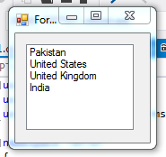
listBox1.Items.Add("Pakistan");
listBox1.Items.Add("United States");
listBox1.Items.Add("United Kingdom");
listBox1.Items.Add("India");
}
}
}
using System;
using System.Drawing;
using System.Windows.Forms;

namespace TEPTUT
{
    public partial class Form1 : Form
    {
        public Form1()
        {
            InitializeComponent();
            String var1 = "Lahore";
            String var2 = "Multan";
            String var3 = "Islamabad";
            String var4 = "Karachi";
            listBox1.Items.Add(var1);
            listBox1.Items.Add(var2);
            listBox1.Items.Add(var3);
            listBox1.Items.Add(var4);

        }

   }
}
using System;
using System.Drawing;
using System.Windows.Forms;

namespace TEPTUT
{
    public partial class Form1 : Form
    {
        public Form1()
        {
            InitializeComponent();

            String[] city = new String[] { "Lahore", "Multan", "Islamabad", "Karachi"};

            for (int x = 0; x < city.Length; x++)
            {
                listBox1.Items.Add(city[x]);
            }

        }

   }
}
using System;
using System.Drawing;
using System.Windows.Forms;

namespace TEPTUT
{
    public partial class Form1 : Form
    {
        public Form1()
        {
            InitializeComponent();


        }

        private void button1_Click(object sender, EventArgs e)
        {
            listBox1.Items.Add(textBox1.Text);
        }

   }
}
using System;
using System.Drawing;
using System.Windows.Forms;

namespace TEPTUT
{
    public partial class Form1 : Form
    {
        public Form1()
        {
            InitializeComponent();

            listBox1.Items.Add("A");
            listBox1.Items.Add("B");
            listBox1.Items.Add("C");
            listBox1.Items.Add("D");

        }

        private void button1_Click(object sender, EventArgs e)
        {

            MessageBox.Show(listBox1.SelectedItem.ToString());
        }

   }
}
using System;
using System.Drawing;
using System.Windows.Forms;
namespace WindowsFormsApplication1
{
    public partial class Form1 : Form
    {
        public Form1()
        {
            InitializeComponent();
        }
        private void Form1_Load(object sender, EventArgs e)
        {
            listBox1.Items.Add("Sunday");
            listBox1.Items.Add("Monday");
            listBox1.Items.Add("Tuesday");
            listBox1.Items.Add("Wednesday");
            listBox1.Items.Add("Thursday");
            listBox1.Items.Add("Friday");
            listBox1.Items.Add("Saturday");
            listBox1.SelectionMode = SelectionMode.MultiSimple;
        }
        private void button1_Click(object sender, EventArgs e)
        {
            foreach (Object obj in listBox1.SelectedItems )
            {
                MessageBox.Show(obj.ToString ());
            }
        }
    }
}
using System;
using System.Drawing;
using System.Windows.Forms;

namespace TEPTUT
{
    public partial class Form1 : Form
    {
        public Form1()
        {
            InitializeComponent();
            listBox1.Items.Add("A");
            listBox1.Items.Add("B");
            listBox1.Items.Add("C");
            listBox1.Items.Add("D");


        }

        private void button1_Click(object sender, EventArgs e)
        {
            listBox1.Items.Clear();
        }

   }
}
using System;
using System.Drawing;
using System.Windows.Forms;

namespace TEPTUT
{
    public partial class Form1 : Form
    {
        public Form1()
        {
            InitializeComponent();
            listBox1.Items.Add("A");
            listBox1.Items.Add("B");
            listBox1.Items.Add("C");
            listBox1.Items.Add("D");
        }

        private void button1_Click(object sender, EventArgs e)
        {
            listBox1.Items.RemoveAt(0);
        }

   }
}
using System;
using System.Drawing;
using System.Windows.Forms;

namespace TEPTUT
{
    public partial class Form1 : Form
    {
        public Form1()
        {
            InitializeComponent();
            listBox1.Items.Add("A");
            listBox1.Items.Add("B");
            listBox1.Items.Add("C");
            listBox1.Items.Add("D");


        }

        private void button1_Click(object sender, EventArgs e)
        {
            listBox1.Items.Remove("A");
        }

   }
}
using System;
using System.Drawing;
using System.Windows.Forms;

namespace TEPTUT
{
    public partial class Form1 : Form
    {
        public Form1()
        {
            InitializeComponent();
            listBox1.Items.Add("A");
            listBox1.Items.Add("B");
            listBox1.Items.Add("C");
            listBox1.Items.Add("D");
        }

        private void button1_Click(object sender, EventArgs e)
        {
    listBox1.Font = new Font(Font.FontFamily, 12);
        }

   }
}
using System;
using System.Drawing;
using System.Windows.Forms;

namespace TEPTUT
{
    public partial class Form1 : Form
    {
        public Form1()
        {
            InitializeComponent();
            listBox1.Items.Add("A");
            listBox1.Items.Add("B");
            listBox1.Items.Add("C");
            listBox1.Items.Add("D");
            listBox1.BackColor = Color.LightCyan;
        }

   }
}
using System;
using System.Drawing;
using System.Windows.Forms;

namespace TEPTUT
{
    public partial class Form1 : Form
    {
        public Form1()
        {
            InitializeComponent();
            listBox1.Items.Add("The");
            listBox1.Items.Add("Engineering");
            listBox1.Items.Add("Projects");
            listBox1.Font = new Font(Font.FontFamily, 15);
            listBox1.BackColor = Color.Black;
            listBox1.ForeColor = Color.White;
        }


   }
}
There are several more events which you can try to make list box more interactive. These events are used to give innovative concepts.
using System;
using System.Drawing;
using System.Windows.Forms;

namespace TEPTUT
{
    public partial class Form1 : Form
    {
        public Form1()
        {
            InitializeComponent();

        }

        private void listBox1_Click(object sender, EventArgs e)
        {
            MessageBox.Show("Warn ! Click is disable..");
        }


   }
}
This event occurs when user will click twice on the Listbox. Supposed you are wanted to perform any action when user will double click on the ListBox, then we will use this event. In the following code, we are changing the back color of ListBox when user will click twice.
using System;
using System.Drawing;
using System.Windows.Forms;

namespace TEPTUT
{
    public partial class Form1 : Form
    {
        public Form1()
        {
            InitializeComponent();

        }
        private void listBox1_DoubleClick(object sender, EventArgs e)
        {
            listBox1.BackColor = Color.Black;
        }
   }
}
To demonstrate double click event, we changed the color. You can code any functionality according to your needs.
This event occurs when user will hover mouse cursor on the Listbox. In the following code, we have changed the foreColor on mouse hover. When the mouse cursor will hover the color of font will be changed.
using System;
using System.Drawing;
using System.Windows.Forms;

namespace TEPTUT
{
    public partial class Form1 : Form
    {
        public Form1()
        {
            InitializeComponent();
            listBox1.Items.Add("The Engineering Projects");
        }

        private void listBox1_MouseHover(object sender, EventArgs e)
        {
            listBox1.ForeColor = Color.Bisque;
        }
   }
}
This event occurs when user will remove the cursor from the Listbox. In the above code, we have changed the forecolor when a user hovers the mouse cursor. In the below code, we will change the forecolor again to black when a user removes mouse cursor.
using System;
using System.Drawing;
using System.Windows.Forms;

namespace TEPTUT
{
    public partial class Form1 : Form
    {
        public Form1()
        {
            InitializeComponent();
            listBox1.Items.Add("The Engineering Projects");
        }

        private void listBox1_MouseHover(object sender, EventArgs e)
        {
            listBox1.ForeColor = Color.Bisque;
        }

        private void listBox1_MouseLeave(object sender, EventArgs e)
        {
            listBox1.ForeColor = Color.Black;
        }
   }
}
This event occurs when user will change the background color of the Listbox. In the following code, we are going to change the color of background when user will hover the mouse on ListBox. When color will change, BackColorChanged event will occur. In which we will show popup message.
using System;
using System.Drawing;
using System.Windows.Forms;

namespace TEPTUT
{
    public partial class Form1 : Form
    {
        public Form1()
        {
            InitializeComponent();
            listBox1.Items.Add("The Engineering Projects");
        }

        private void listBox1_MouseHover(object sender, EventArgs e)
        {
            listBox1.BackColor = Color.Bisque;
        }

        private void listBox1_BackColorChanged(object sender, EventArgs e)
        {
            MessageBox.Show("BackGround Color is changed !!");
        }

   }
}
This event occurs when user will change the foreground color of the Listbox. In the following code, we will be used mouse hover event to changed the foreColor and ForeColorChanged Event also. The forecolorchanged event will raise the message popup when a color of the foreground is getting changed.
using System;
using System.Drawing;
using System.Windows.Forms;

namespace TEPTUT
{
    public partial class Form1 : Form
    {
        public Form1()
        {
            InitializeComponent();
            listBox1.Items.Add("The Engineering Projects");
        }

        private void listBox1_MouseHover(object sender, EventArgs e)
        {
            listBox1.ForeColor = Color.Bisque;
        }

        private void listBox1_ForeColorChanged(object sender, EventArgs e)
        {
            MessageBox.Show("ForeGround Color is changed !!");
        }

   }
}
This event occurs when user will select any item in the Listbox. In the below code I have taken two list box. When user will select any value from the first list box then according to that value listbox2 will show it's valued.
using System;
using System.Drawing;
using System.Windows.Forms;

namespace TEPTUT
{
    public partial class Form1 : Form
    {
        public Form1()
        {
            InitializeComponent();
            listBox1.Items.Add("The Engineering Projects");
            listBox1.Items.Add("C# Tutorials");
        }


        private void listBox1_SelectedIndexChanged(object sender, EventArgs e)
        {
            if (listBox1.SelectedIndex == 0)
            {
                listBox2.Items.Clear();
                listBox2.Items.Add("Arduino Projects");
                listBox2.Items.Add("Proteus Projects");
                listBox2.Items.Add("Matlab Projects");
            }
            else
                if (listBox1.SelectedIndex == 1)
                {
                    listBox2.Items.Clear();
                    listBox2.Items.Add("C# Label");
                    listBox2.Items.Add("C# TextBox");
                    listBox2.Items.Add("C# ComboBox");
                }
        }

   }
}
If you wanted to test the above code, then place two list boxes and copied the above code.
We have tried to give basics to major concepts of C# ListBox. All the above codes are working fine and added after testing. If you will cover all the above codes then you will become able to play with ListBoxes. ListBoxes play very important roles in Point Of Sale applications. Thanks for reading our tutorial, moreover you can watch ListBox video.
Button are reusable components such as the exit and quit buttons which will perform the same functionality in each form and able to reuse again and again. The button will give end-user quite a clear navigation of software. The shape of the button is unique and have its own appearance properties by which its user can easily judge where is the button located. In short, the button is the controller which is used to create interactivity between user and application. Did you know that button is directly inherited from its base class? which is ButtonBase. You can click the button with the mouse and even with keyboard keys, it depends on the situation. So, let's have a look at How to sue C# Button Control:
There are two ways using which you can add the C# button into your program. First one is the programming way to create a button.It's quite difficult one. The second way is to drag the button directly from the toolbar and place it on your application. Which is much easier than the programming one. When you drag the button you will get the default name of the button as button1 which you can change from the right panel under the properties tab.
button1.Text = "TEP Button Example Text";
button1.Image = Image.FromFile("C:\\Users\\Jade\\Pictures\\brownImage.jpg");
button1.BackColor = Color.Aqua;
button1.ForeColor = Color.White;
button1.BackColor = Color.Black;
button1.ForeColor = Color.White;
button1.BackColor = Color.Black;
button1.Font = new Font(button1.Font.FontFamily, 33);
int newSize = 33;
button1.ForeColor = Color.White;
button1.BackColor = Color.Black;
button1.Font = new Font(button1.Font.FontFamily, newSize);
Now we will create the code of above-listed events and handle them with their methods. You can create separate methods and appoint them in replacement of built-in methods. But that's some difficult, so we will simply use the built-in methods.
This event will occur when end user will click on the button once. If you want to perform any functionality when user will click on the button then we will use the _Click event to handle this functionality. After the name of a button, you have to write the _Click, suppose you go with default name which is button1. Then you have to create the method with name button1_Click. In the following code, I have used the button when user will click, it will generate the message box.
using System;
using System.Drawing;
using System.Windows.Forms;

namespace TEPTUT
{
    public partial class Form1 : Form
    {
        public Form1()
        {
            InitializeComponent();
        }
        private void Form1_Load(object sender, EventArgs e)
        {

        }

        private void button1_Click(object sender, EventArgs e)
        {
            MessageBox.Show("C# Button Click Event Executed");
        }


   }
}
This event occurs when the text of the button is changed. This is the built-in method with the name _TextChanged. In the following code, there is a button1_TextChanged event which will generate the message popup when the text of the button is changed. Button1_Click event is used to change the text when user will click. Logic is when user will click the button, the text of button will be changed and button1_TextChanged is performed.
using System;
using System.Drawing;
using System.Windows.Forms;

namespace TEPTUT
{
    public partial class Form1 : Form
    {
        public Form1()
        {
            InitializeComponent();
        }
        private void Form1_Load(object sender, EventArgs e)
        {

        }

        private void button1_Click(object sender, EventArgs e)
        {
            button1.Text = "New Text";
        }


        private void button1_TextChanged(object sender, EventArgs e)
        {
            MessageBox.Show("C# Button TextChanged Event");
        }


   }
}
This event occurs when user will hover the mouse cursor on the button. This is a built-in event with the name _MouseHover after the default name of the button or your desired button named. Here in this code, we have used the default name of a button which is button1. When user will hover the mouse cursor over the button it will generate the message popup.
using System;
using System.Drawing;
using System.Windows.Forms;

namespace TEPTUT
{
    public partial class Form1 : Form
    {
        public Form1()
        {
            InitializeComponent();
        }
        private void Form1_Load(object sender, EventArgs e)
        {

        }


        private void button1_MouseHover(object sender, EventArgs e)
        {
            MessageBox.Show("C# Button MouseHover Event");
        }


   }
}
This event is occurring when user will leave the button or move the cursor from the button boundaries. In the following code, we have created the _MouseLeave event with the default name of the button. When user will remove the mouse cursor out of button it will get executed and generate the message popup.
using System;
using System.Drawing;
using System.Windows.Forms;

namespace TEPTUT
{
    public partial class Form1 : Form
    {
        public Form1()
        {
            InitializeComponent();
        }
        private void Form1_Load(object sender, EventArgs e)
        {

        }

        private void button1_MouseLeave(object sender, EventArgs e)
        {
            MessageBox.Show("C# Button MouseLeave Event");
        }


   }
}
Now you are able to add functionalities in C# button. We have tried to explain you the major concepts so that you can get the idea to work with C# button. By using the above events you can make your software more accurate and interactive. We have described the basic two major functionalities. Now you are able to change text, color, style, and handle the events. If are facing any kind of problem regarding the codes, let us know through the comment section.