Hello readers! Welcome to the easiest explanation of the current divider circuit. I hope you are doing well. In electrical and electronic circuits, the current distribution among different components and branches is the fundamental concept and it must be crystal clear in mind to understand the circuit working. One key concept that helps to understand this flow is the current divider rule, which is purely related to the parallel circuits. It is the method of determining electrical current flow into multiple paths of the parallel connection circuit. Today, we’ll shed light on the basic introduction of the current divider and the discussion will start from scratch. You’ll see the basic concepts of the circuits, working, derivation, and applications of the current divider in the circuit. Moreo ...
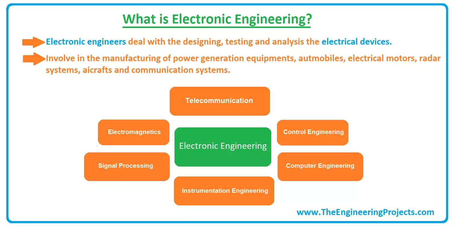
Hello Friends! I hope you are doing well. Today, we are going to discuss a very comprehensive branch of engineering named "Electronic Engineering". We will cover the following content: Branches' of Electronic Engineering, electronic engineering vs electrical engineering, electronic engineering jobs, electronic engineering salary, electronic engineering courses, electronic engineering degree, final year project ideas of electronic engineering and top electronic engineers & their contribution. Trust me; this is going to be very informative. So let's get started! Electronics engineering is actually a sub-field of electrical engineering, but a broad field itself and further divided into various sub-fields such as analog electronics, consumer electronics, digital electronics embedded electronic ...
Hello friends, I hope you all are doing great. In today’s tutorial, we will have a look at What is Bistable Multivibrator and how it can be used in different circuits. In this type of multivibrator, the circuitry can operate in any state according to a signal provided at its input while it does not happen in a monostable multivibrator. This arrangement is also defined as a flip flop because flip flop also operates at more than one condition. It also has the ability to store a single bit of information so it is mostly used in logic circuits and in computer data storage part. This vibrator like other vibrators is used for the production of square waves with providing some delay. These circuits are constructed with numerous kinds of semiconductor components. The most used semiconductor device ...
Hello fellows, I hope you all are doing great. In today’s tutorial, we will have a look at What is Monostable Multivibrator. It is a simple electronic circuit, used to produce a pulse at its output also known as one shot. It generates output pulses according to corresponding circuitry requirements. Its main feature is that after the generation of the output pulse, it regains its stable state and does not produce any further output pulse till not triggers again. This circuitry can be considered as a biased form of multivibrator (such circuitry that is used for implementation of 2-state modules like timers) that is (on) operating in the starting condition till the triggered point and then becomes unstable on its own. In today's post, we will have a look at its circuitry, construction, workin ...
Hello friends, I hope you all are doing great. In today’s tutorial, we will discuss What is Star Delta Transformation . We will also have a look at its inverse i.e. Delta to Star Transformation . In electrical systems, we have to deal with resistances a lot, arranged in different patterns i.e. parallel, series, mesh etc. Simple single-phase resistive circuits, where resistances are present in parallel or series combination, can be solved by using series or parallel formulas of resistances, there are also few other techniques i.e. Kirchoff's Laws, nodal analysis etc. to solve such circuits. But in the case of complex 3-phase resistive circuits, we can't use these basic formulas & thus need better techniques. Star to delta transformation method is one of them. The star to delta transformatio ...
Hello friends! This page brings together our electronics projects using Arduino, PIC microcontrollers, 8051 devices and the 555 timer. You can use it as a learning path: begin with a simple input or output, understand the circuit, then combine those building blocks into a more complete application. Many linked tutorials include Proteus simulations, source code or other supporting files. Read each project for its exact requirements and download details. I encourage you to rebuild the circuit yourself before studying the supplied solution, because identifying a wrong connection or timing assumption teaches skills that copying a finished schematic cannot provide. We will keep the original project links grouped by platform, explain what each group teaches and add a practical method for choosin ...