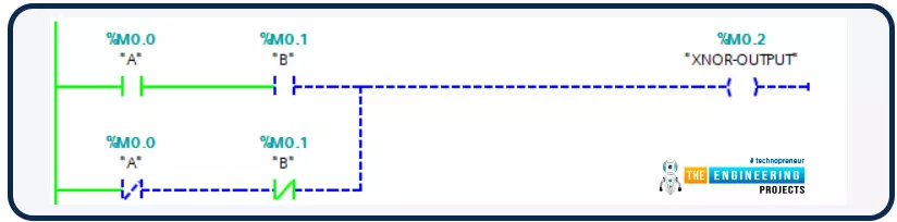
Hello friends, all of us know that PLCs are nothing but the smartest migration from relay logic control to programmable logic control. Also, you know clearly that, logic is the heart of any programming language, and the same is applied to ladder logic programming. Bitwise operators represent the logical operations including the basic logical operations like AND, OR, and NOT and the derived logical operations like NAND, NOR, and XOR. in most cases, for each bitwise operator, there are inputs based on which the output can be decided. Some of these bitwise operators have two inputs and some have only one input. In this article, we are going to present how we can use these bitwise logical operators and their instructions with examples and practice using the PLC simulator.
Logic Gates ba ...
Hi friends, today we are going to explore mathematical computations in ladder logic. Like in any programing language you should find logic and mathematic computations, here in PLC programming you often need to process the input data that is collected from reading analog devices like temperature, level, flow et cetera. Then you need to run some calculations on this data to derive some other variables for deciding to run or stop some device or even to determine analog output to output to analog device i.e. valve or actuators. In the following sections, we are going to explore the mathematical functions and their input operators and outputs as well. Then we will show how to utilize such functions in ladder logic with simple examples and as usual enjoy practicing them thanks to the PLC simula ...
Hello friends, welcome back to our tutorials on PLC ladder logic programming. Today we will talk about batch process control and take one project from our factory to understand, implement, and simulate. So without any further delay, let’s jump into the tutorial by asking what is batch process is if it is different from other online processes. Well! The batch process is defined as a process that starts by operating continuously till the end of the cycle without any interaction with the users. For you guys, it’s cool to know that most of the processes you might meet in the industry of batch-type processing. Do you like me to give an example? Well! The Silo cement process is a batch process, and food and beverages manufacturing are also good examples of batch processes. So what do we have tod ...
Hi friends, I hope you are very well; today in this tutorial, we will practice conditional jumping for performing some code at the occurrence of some conditions. Like any other programming language, jumping is one of the most common approaches to transfer the execution from its sequential mode to run different processes or instructions marked by a label and bypassing the lines of codes in between the last executed transaction before the jump instruction and the labeled instruction whom the program is going to move to. The good thing about this technique is shortening the scan cycle of the program due to not running the whole program. However, using jumping techniques in coding is very dangerous. It would help if you were careful of missing some op ...
Hi friends! I hope you are doing well! Today we are going to learn and practice a new topic which is a very crucial technique in plc programming. the topic is called “latching”. We mean by Latching to keep the output running starting from the instance of giving a kick-off command until we hit a command to stop running of the motor. Imagine my friends, operator wants to start a motor by hitting a start push button and want the motor to keep running and leave and go for doing another task or job. And then it keeps running until the operator wants to stop it. The problem here is that, once the operator releases his hand away from the push button, the motor automatically stopped and that is not like what the operator wants to do with the motor. To clear the problem that we are going to solve, ...
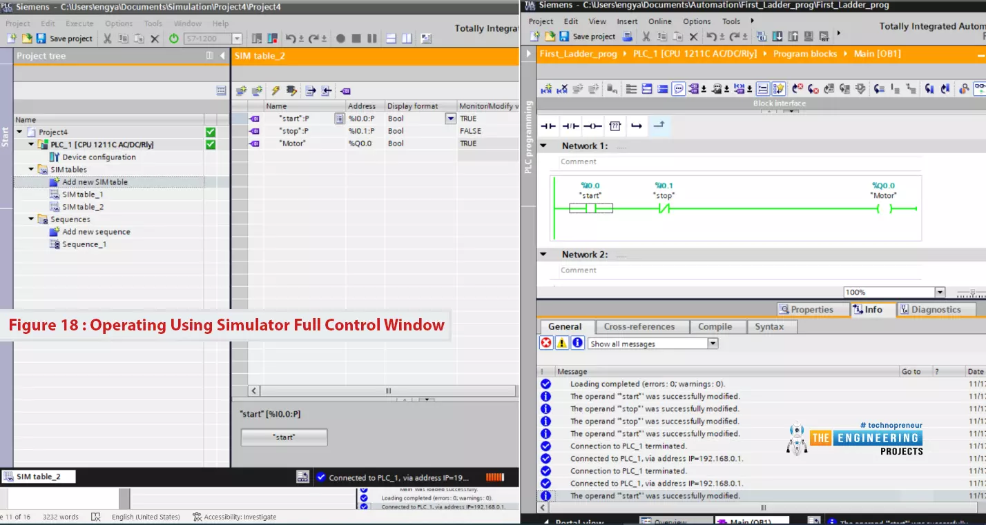
Hello friends, I hope you all are doing great. In today's tutorial, I am going to create the first Ladder Logic Program in PLC Simulator. It's 3rd tutorial in our Ladder Logic Programming Series. In our previous tutorial, we have installed PLC Simulator and now we can say our lab is ready to learn and practice. So let us get to work and get familiar with the ladder logic components.
After this article, you will have a complete understanding of PLC contact and coil including their types and possible causes. Because they are the building block of any rung of a ladder logic program. So let us start with ladder logic rung components.
Ladder Logic Contact/Input
In ladder logic programming, a contact represents the input of the system and it could b ...
Hello, my friends, again we are back and enjoying one of the new tutorials in our ladder logic programming series. The tutorial we are here to present comes with a new project: dual compressors management using PLC. In that very project, you are going to learn how to divide the process between two actuators aiming to prolong the lifetime of the equipment and fulfill the processing requirements. as we used to do every tutorial, will go through the project. Understand the requirements, and design for the solution. And then code the ladder logic program of the solution and for sure enjoying simulating the code to validate the functionality of the proposed code. So without any more delay, let’s get started on our project.
What’s dual compressors project
The picture of the project shown in fi ...
Hi, my friends, and welcome back to enjoying together learning and practicing PLC ladder logic programming with a new project from the actual industry. Today my friends, we will continue the bottle line project to complete the capping and filling of the bottling line. As usual, we will describe the requirements as the clients ask us to do. Then we list all the inputs and outputs we will use to make our design work. Afterward, we write the ladder logic program into two sub-tasks. We make one to perform the filling and the second for the capping process. So, without further delay, buddies, let’s jump into the work.
Filling and capping project
Let me introduce the project as two processes we have been requested to implement here. We are filling bottle process in which we need to control the ...
Hello friends, hope you all are having fun with your lives. Today, I am going to share links related to PLC projects. I have shared few PLC projects on my blog so here on the post I am gonna compile a list and will post all the PLC projects posted till now. I will keep on updating this list so stay tuned.
All the PLC projects posted here are completely designed by our team so if you wanna copy them then you are most welcome but do mentioned the link of respective project as a favor. Its not a very big list rite now but I am gonna update more projects real soon and will update the list. So, let's get started with PLC projects:
PLC Projects
Here's the complete list of PLC projects posted till now on our blog:
Introduction to PLC.
Introduction ...
Hello friends, we are going to learn and practice together one project from the industry. It is the bottle line production in which many processes are happening, including but not limited to filling, capping, and conveying from the start point where the bottles get in the line to the end point where the bottle gets out from the line. In the process, many concerns and restrictions must be addressed, like the bottle size, length, broken status, pretty full or empty, etc. So we have a lot to learn, program, and test right here in this project. Let’s jump into work and enjoy completing such an exciting project without further delay.
Bottle Line Assembly: Introduction
Figure 1 images the project we are going to do. Yes, it’s a massive project, with too many things we see to control. However, ...