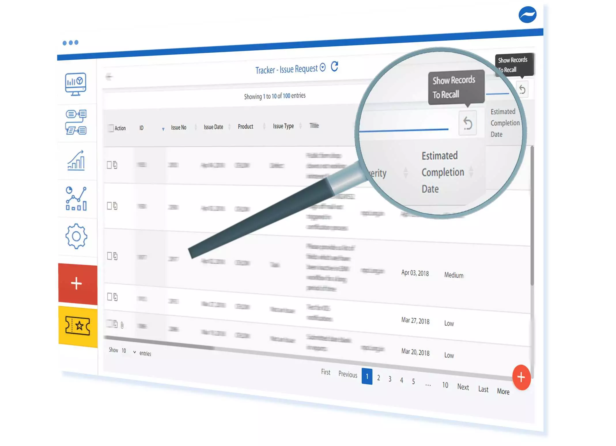
Optimizing the well cycle portfolio is done by assessing the investments secured by the company’s management and opting for software systems assigned to the operational needs. Allocation of funds for equipment, vendor contracts rigs and accounts constitute the bulk of expenses for each project. The use of capital planning oil and gas software, requires evaluation and quality assessment before money is diverted towards it. This could be a daunting task in a market where prices fluctuate daily. Are you aware of the needs before relying on an expensive complex software?
We shall try to relieve your pain points, take a test and undergo proper trials before considering the next purchase. Then select a vendor who can put together the system for long-ter ...
Hello friends, i hope you people are fine and enjoying. Proceeding to my previous tutorial, in which i explained Brushless DC motor in detail. Now in this tutorial i am going to explain in detail the second type of DC motor which is Brushed DC motor. In this tutorial, we will see what is in fact a Brushed DC motor, how it works and what are the advantages and practical application of this type of motor on some other type of motors.
Brushed DC motors are also known as commutated DC motors. Reason is that these motors contain commutator and carbon brushes for rotor excitation. I will explain all these terminologies in detail, later in tutorial. These are the most important type of motors designed to run directly on DC power supply. These were the ve ...
Hello friends, I hope you all are having fun. In today's tutorial, we will have a look at Series Clippers & their types in detail, we will also implement the simulations of Series Clippers in Proteus software. In the next article, we will discuss the next two types of Clippers i.e. Shunt Clippers & Dual Clippers. Today, We are going to learn:
What is a Clipper?
What are the types of Clippers?
Series Clippers Simulations in Proteus.
So, let's get started:
What is a Clipper???
Clipper (also known as Limiter) is an electronic circuit, which clips or limits the amplitude(positive, negative or both) of an AC source wave.
Diodes are normally used for designing Clippers and such circuits are normally referred as Diode Clipping Circuits (Diode Limiting Circuits).
...
Hello everyone! I hope you all will be absolutely fine and having fun. In the tutorial Interfacing Temperature & Humidity Sensor with Arduino I will tell you that how can you interface temperature and humidity sensor named as DHT11 with Arduino and how can you observe the temperature and humidity level using this sensor. This sensor has usually three pins but some of its types has four pins but only the three pins are of importance for us e.g. VCC, GND and the third pin for reading the data from the sensor.
In the tutorial Interfacing Temperature & Humidity Sensor with Arduino, I will make a simple Arduino program which will estimate the level of temperature and humidity continuously and will display the value of both temperature and hum ...
Hi Friends! Hope you’re well today. I welcome you on board. In this post today, I’ll walk you through the key benefits of data visualization.
Data visualization is something that used to be a competitive advantage, but now it is becoming a necessity to survive.
I have outlined some of the key benefits of data visualization and I will explain each point very briefly. If you take one thing away from this post it should be that data visualization is important and you should be implanting data visualization techniques into your business or organization.
Reducing Errors
Keeping track of your data will let you tell a story about your customers and your business. One negative part of the story is that data visualization will let you identify the prob ...
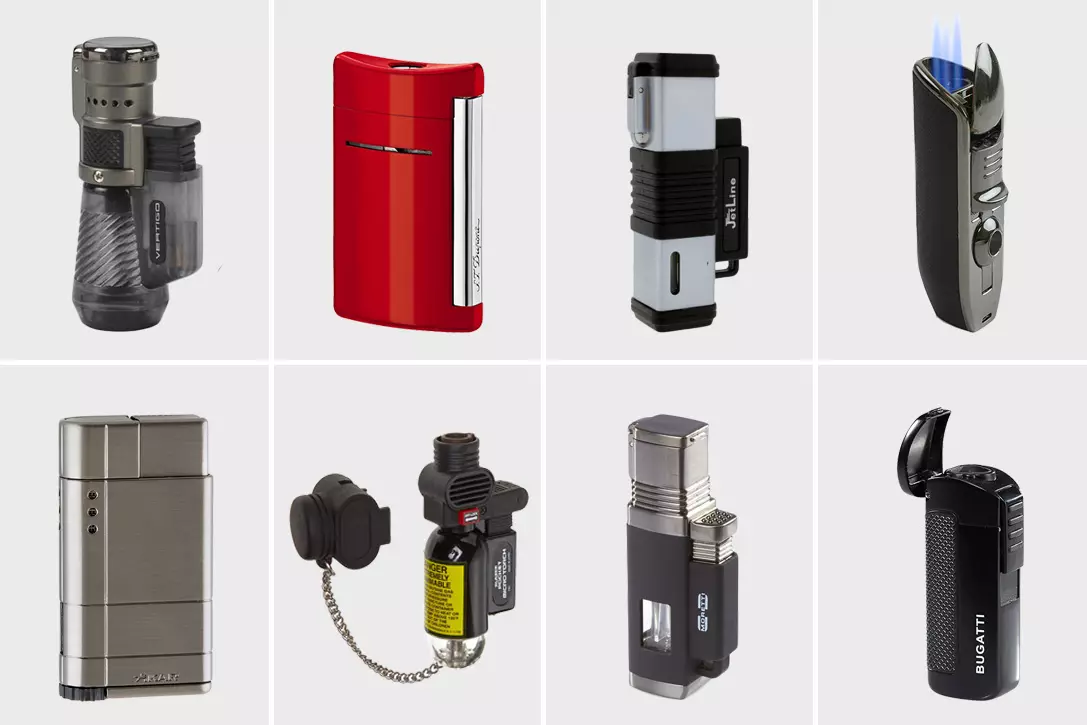
Lighters are popular for the cigar smokers but not only have the smokers used the lighters but also for the people who are interested in camping, picnicking and any other activities in the outside the windy environments. Usually, cigar smokers prefer butane torch lighters during the smoke.
A torch lighter is a portable thing that is used for instant flame or fire. It is used for many activities like outside cooking, lightening in the dark area, fishing, and many many activities. Butane torch lighter in an instrument that is worked by utilizing butane creates hot flames.
If you can’t buy a good torch lighter, it can make you in trouble in a serious condition. Suppose you are when you need instant fire and you have a lighter and unfortunately your ...
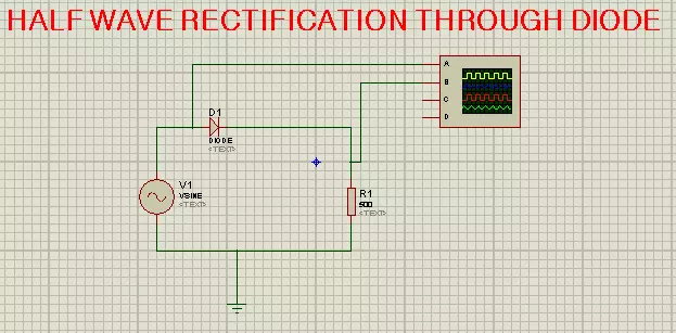
Hello friends, I hope you all are doing great. In today's tutorial, I will show you how to perform Simplest Half Wave Rectification in Proteus. In this tutorial, we will design a simple Proteus simulation, where we will use a diode for half-wave rectification.
Before designing the Proteus simulation, we will first have a theoretical overview of Half Wave Rectification as it's always the best approach to read theory before practical (Proteus Simulation). So, let's get started:
What is Rectification ???
Rectification is an electrical process, used to convert Alternating(AC) Voltage into Direct(DC) Voltage using a circuit called rectifier.
The Rectification process is always carried out using diodes, as we know diodes allow the current to flow in one direction only, thus t ...
Hello everyone! I hope you all will be absolutely fine and having fun. Today, I would like to provide a complete discussion on DC Motor Control using myRIO. I will first provide you a bit information about DC motor then we will move forward towards DC motor control using myRIO. DC motor is an electronic instrument which is used to convert electrical energy into mechanical energy. It plays a vital role in industrial applications. It has also great importance for the engineers to to study about its working principle. DC motor has basically two input terminals. At one terminal we have to provide voltage supply and the other terminal will be attached to the ground (0V). And if we change the polarity, the direction of the motor will also be changed co ...
Hi Guys! Hope you're well today. Glad to have you here. In this post today I'll detail why EV pickup trucks will spearhead the switch to electric motors.
In 2019, approximately 63 percent of Americans looking to buy a car were interested in buying an EV, according to Consumer Reports. The stage is set for major EV manufacturers to contend over the market. Of all body styles, pickup trucks seem to be of particular interest to them. General Motors, Tesla, and Ford are doubling down their efforts in EV pickup design. This is all so that models like the Hummer EV and the Cyber truck can release within the next few years.
Trucks are favored for their towing power, traversal abilities, and relatively low need for maintenance. Those are perfect attribu ...
Hello everyone! I hope you all will be absolutely fine and having fun. Today, I am going to share my knowledge about Calculating Values of Trigonometric Functions in MATLAB. Trigonometric function have a great importance in latest mathematics. There are six types of trigonometric functions out of which first three are used more frequently in comparison to the other three. Trigonometric functions are important in the study of triangles.
Trigonometric functions show the relationship between the angles of the triangle and the lengths of its sides. The positive and negative signs with the trigonometric functions indicate the portion of the quadrants. Well known theorem of mathematics i.e. Pythagoras Theorem is used in case of the right angle triang ...