Hello friends! In this tutorial, we will learn how to share a Simulink design without distributing its editable implementation. You may have developed a controller, a signal-processing algorithm or a plant model that another person needs to simulate. The challenge is to give that person a usable component while keeping your original design private. The original version of this tutorial used a generated S-function. We will keep that method, explain what it actually protects and then look at the protected-model workflow available in current Simulink releases. These approaches produce different deliverables, so the right choice depends on what the recipient needs to do. If you are distributing MATLAB functions rather than Simulink models, see our tutorial on converting MATLAB M-files to P-fil ...
Hello friends, I hope you are doing well. Today we will convert a MATLAB M-file into a P-file so another MATLAB user can run our function without receiving its readable implementation. We will start with one small calculation, create its P-code version, and then organize a distribution folder that includes everything needed to use it. The basic command is short, but a reliable delivery requires a few additional decisions. Where will MATLAB write the output? Which copy of the function will run? Does the recipient have a compatible MATLAB release and the required toolboxes? We will answer these questions as we work through the example. Figure: An example of readable M-file source; use the tutorial's pcode commands for conversion. What Are M-Files and P-Files? An M-file is a readable MATLAB p ...
Hello friends, I hope you are doing well. In this tutorial, we will compare alternating current and direct current, calculate power in both systems and explain why modern electrical networks use each form. AC and DC describe the direction and time variation of voltage and current. Power is the rate at which electrical energy is transferred. The phrase “AC power” therefore means power carried by alternating voltage and current, while “DC power” means power carried by quantities with fixed polarity. Figure: A conceptual image introduces the comparison of alternating and direct current. AC and DC at a Glance Feature DC AC Polarity Remains fixed Reverses periodically Typical waveform Constant or varying unidirectionally Sinusoidal or another bipolar waveform Frequency Zero for ideal steady DC ...
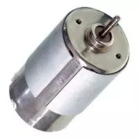
Hello everyone, I hope you are doing well. In this tutorial, we will compare DC and AC motors from their operating principles to their speed control, maintenance and applications. Both convert electrical energy into mechanical energy through electromagnetic force, but those broad labels contain several different motor families. The first important correction is that an AC motor is not simply a DC motor with continuous slip rings. Most industrial AC motors create a rotating stator field and use either induction or synchronous interaction to produce rotor torque. We will therefore compare common brushed DC motors, brushless DC motors, induction motors and synchronous AC motors. Figure: A small DC motor introduces the comparison of DC and AC motor operation. DC and AC Motor Comparison Feature ...
Hello friends, I hope you are doing well. Welcome to our Difference Between engineering series. In this series, we compare two related technologies side by side so you can understand where they are similar, where they differ and when each one should be selected. A useful comparison goes beyond short definitions. We will begin with the physical principle, compare construction and operating behavior, add equations or ratings where they clarify the subject, and finish with practical selection guidance. This format is useful for students preparing for examinations and interviews, but it is equally useful when an engineer must choose between two real design options. Figure: Banner for the engineering comparison series and its tutorial index. Difference Between Tutorial Index No. Comparison Main ...
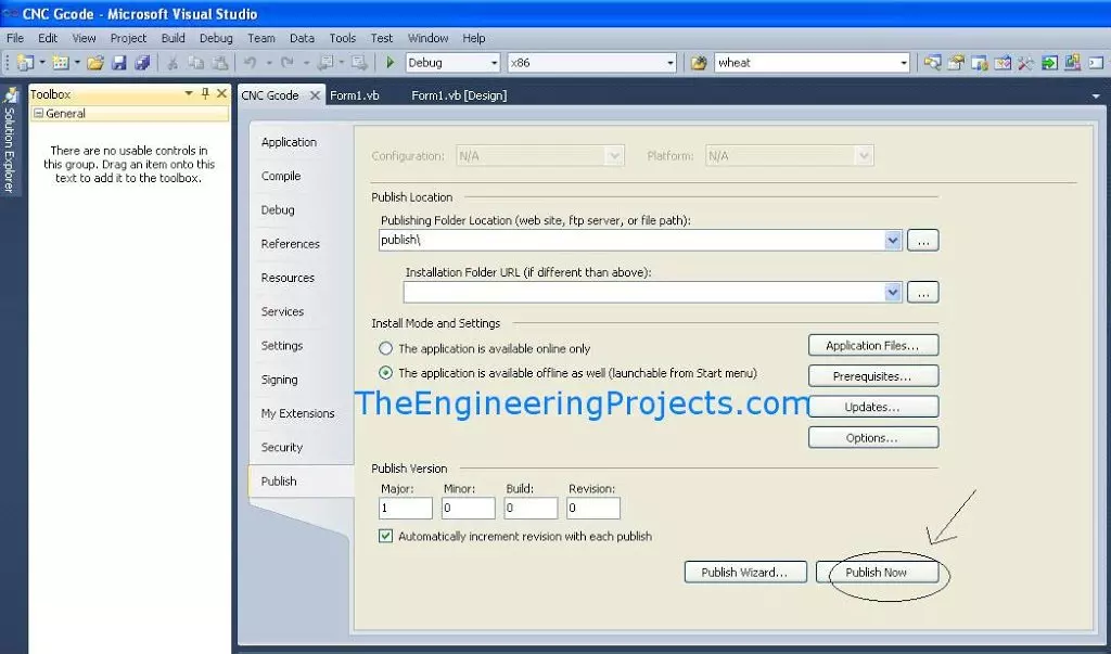
Hello friends, I hope you are doing well. In this tutorial, we will publish a Visual Basic or C# Windows Forms application from Visual Studio 2010 by using ClickOnce. This is useful when you have completed a desktop program, such as the serial terminal from our Serial Port in VB 2010 tutorial , and want to install it on another Windows computer. Visual Studio 2010 is a legacy environment whose Microsoft support ended in July 2020. We are keeping it here because the original project and screenshots use that version. For a new application, use a supported Visual Studio and .NET release and follow the current deployment workflow. Figure: The Publish tab contains the original project's ClickOnce deployment settings. Build Output, ClickOnce and MSI Are Different The phrases EXE file and setup f ...
Hello friends, I hope you are doing well. In this tutorial, we will design the timing logic for a modified sine-wave inverter and study the original CD4047B and CD4017B approach. We will also develop an equivalent microcontroller timing example so you can see exactly how the positive, zero and negative intervals are produced. This article follows our tutorials on the basics of inverter topologies , the major inverter components and the pure sine-wave inverter . A modified waveform is simpler than filtered SPWM, but its harmonic content limits the loads that should use it. Figure: The comparison shows sinusoidal and stepped waveforms over a labeled 20 ms cycle. What Is a Modified Sine Wave? A modified sine wave is a stepped bipolar waveform. During each cycle, the inverter applies a positiv ...
Hello friends, I hope you are doing well. In the previous tutorials, we studied the basics of inverter topologies and the major components of an inverter . We will now connect those ideas and study how an AVR controller can create a sine reference for a pulse-width-modulated inverter. This tutorial explains the signal chain, frequency calculations, H-bridge states, LC filter and transformer. The AVR code is an educational SPWM reference generator for an ATmega16 running at 8 MHz. It is useful for simulation and low-energy waveform testing, but it must not be connected directly to power MOSFET gates. A physical inverter needs proper high-side and low-side gate drivers, hardware dead time, current limiting, voltage feedback, thermal protection and a safe PCB layout. The original project pack ...
No. Inverter tutorial series 1 Basics of Inverters with Topology 2 Major Components of Inverters 3 Pure Sine Wave Inverter Design with Code 4 Modified Sine Wave Inverter Design with Code Hello friends, I hope you are doing well. In the previous tutorial, we studied the basic inverter topologies . We will now examine the components that turn a topology into a working power converter. An inverter is a system rather than a single H-bridge. The controller creates switching commands, gate drivers translate those commands into high-current gate pulses, power semiconductors process energy, capacitors and magnetics store and filter it, sensors close the feedback loop, and protection circuits stop unsafe operation. The thermal design, PCB layout and enclosure are also functional parts of the conver ...
No. Inverter tutorial series 1 Basics of Inverters with Topology 2 Major Components of Inverters 3 Pure Sine Wave Inverter Design with Code 4 Modified Sine Wave Inverter Design with Code Hello friends, I hope you are doing well. This is the first tutorial in our inverter series. We will begin with the purpose of an inverter, study the common output waveforms and then compare the power-stage topologies used to produce AC from a DC source. An inverter looks simple in a block diagram, but a useful design must control voltage, frequency, waveform quality, current, temperature and fault energy at the same time. A circuit that produces an alternating voltage on an oscilloscope is not automatically a safe or well-regulated AC power source. Our goal here is to understand the engineering decisions ...