… for the UART of your board Serial Monitor Expert : the serial monitor with extra debugging tools LCD Library for Proteus V3.0 : 16x2, 20x4 and I2C LCDs to show your readings In the next few days, I will keep on sharing Proteus Libraries of different analog …
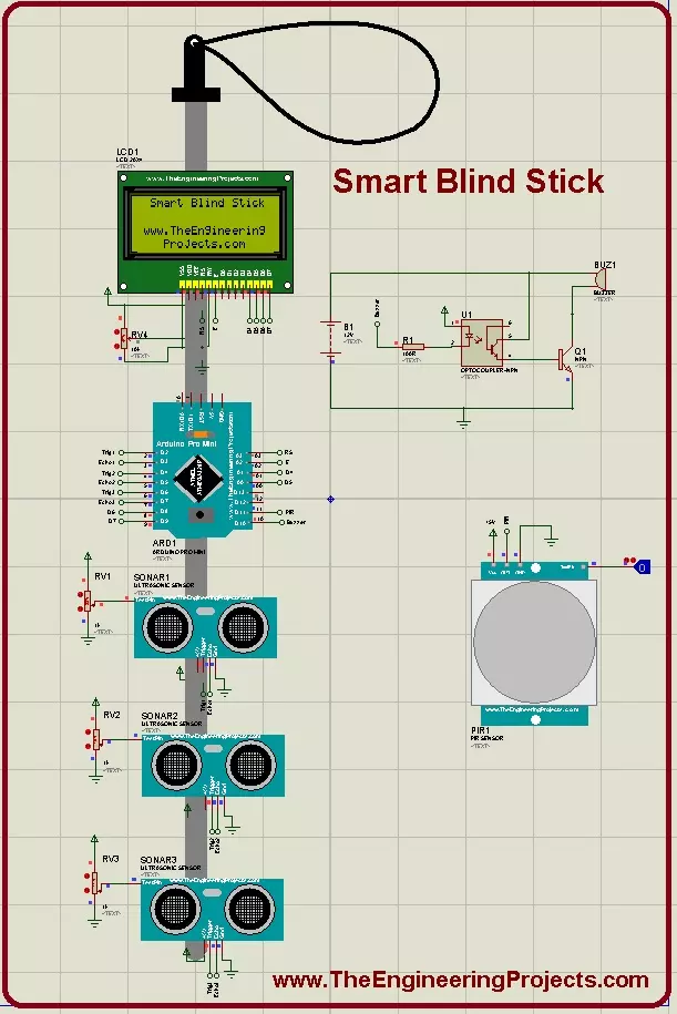
… should download Arduino Library for Proteus . ) Buzzer. ( You should read Simulation of Buzzer in Proteus . ) LCD 20 x 4. ( You should download LCD Library for Proteus . ) Three Ultrasonic Sensors are placed in Front, Left and Right Directions. Ultrasonic …
… an LCD to a Raspberry Pi board. The PCB count for user connections can be zero. Pins 18 (GND), 23 (RS/RW), and 18 (EN) are hardwired to the LCD. The Raspberry Pi's GPIOs (24, 16, 20, 21) are linked to the LCD's data ports (D4, D5, D6, D7). The LCD backlight …
… for the UART of your board Serial Monitor Expert : the serial monitor with extra debugging tools LCD Library for Proteus V3.0 : 16x2, 20x4 and I2C LCDs to show your readings PC 817 has an internal LED and a photo transistor. The photo transistor's base becomes …
… a Proteus Simulation in which I will interface Arduino GLCD together. GLCD is also called Graphical LCD so today we are gonna do some designing on the LCD. The GLCD I am going to use is ks0108 and its model in Proteus is LGM12641BS1R and I have shared the …
… for the UART of your board Serial Monitor Expert : the serial monitor with extra debugging tools LCD Library for Proteus V3.0 : 16x2, 20x4 and I2C LCDs to show your readings First: Microcontrollers operate at 5V while motors operate at different voltages (5V, …
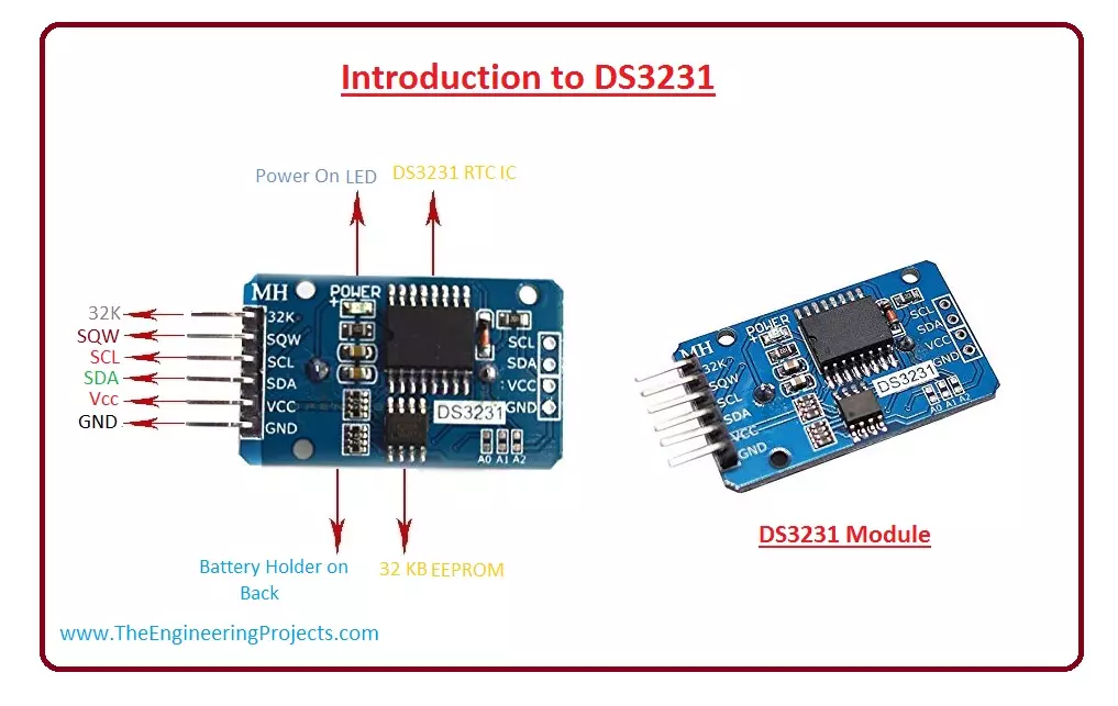
… pin of RTC Module with +5v and GND of Arduino. For output, I have interfaced LCD with this circuit. Connect E and RS pins of LCD to 7 and 6 of Arduino, also connect D4-D7 of LCD to 5-2 of Arduino pins. For further information, let's see its circuit diagram. …