Hello Mentees!, I hope you have a productive day. Welcome to The Engineering Projects. In the previous lecture, we discussed the XOR Logic Gate and designed its circuit using basic logic gates i.e. AND, OR and NOT. Today, I am going to explain another Logic Gate named XNOR Gate in detail.We are going to discuss these concepts in today's lecture:
What are Exclusive NOR Gates
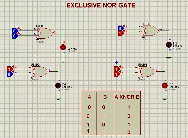
Experimental Proof in Proteus ISIS.
How Truth Table of Exclusive NOR Gate is designed.
How is its Timing Diagram?
Circuit of Exclusive NOR Gate in Proteus Simulation
Applications of Exclusive NOR Gates
XNOR Gate
The exclusive NOR Gate(also called XNOR Gate) simply inverts the output of the XOR Gate(we discussed in the last lecture).So, if we simply place a NOT Gate in front of the XOR Gate, we wi ...
Hi Mentees! I hope you all are having a Productive Day. In our previous lecture, we discussed the DLD Basic Logic Gates and simulated them in Proteus. Today, we are going to use these standard logic gates and will design another logic gate named NOR Gate and will also simulate it in Proteus.
In this tutorial, we'll learn the following concepts:
What is a NOR Gate?Why NOR is called Universal Gate?
How to derive other Gates through NOR Gate?
Advantages of NOR Gate.
Let's begin the exploration:
What is a NOR Gate?"NOR gate is designed by inverting the output of an OR Gate, so it gives a HIGH output, only when all the inputs are LOW."In simple words, a NOR Gate has an OR Gate followed by the NOT Gate, as shown in the below figure:
...
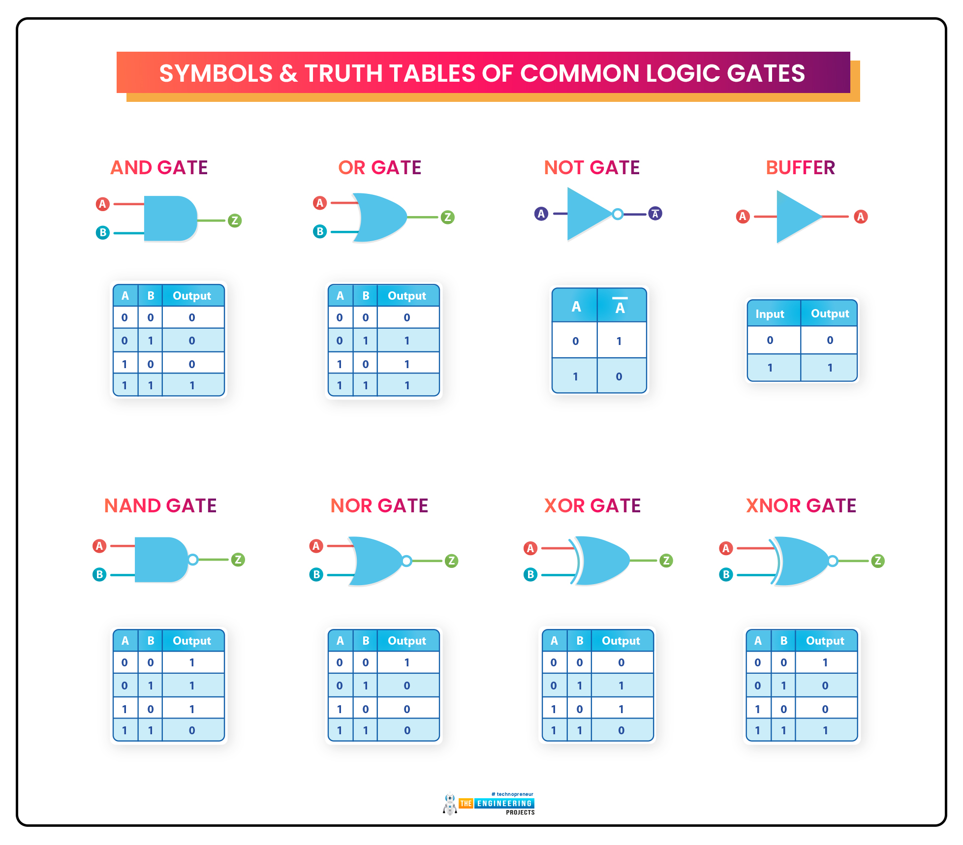
Hello Mentees! I hope you all are doing well. In today's article, we'll learn about the very basic pillar of Digital Logic Circuits i.e. Logic Gates. As we know, the digital world depends on Boolean digits either 0 or 1. So, there's always a need to perform different operations on these boolean numbers i.e. addition, subtraction, multiplication, shifting etc. In order to perform these operations on the binary signals, we use Digital Logic Gates in DLD circuits.So, let's have a look at What is a Logic Gate:What is a Logic Gate?
Logic Gates are designed to perform a specified operation(i.e. addition, bit shift etc.) on the input signals and generate the output signal.
For example, a simple NOT gate takes a single binary input and returns its inverse in the output, i.e.If Input is 0, the Ou ...