Hello friends, I hope you all are doing great. Today, I am going to share the xG24 Dev Kit Library for Proteus, so you can run a Bluetooth LE sensor simulation of Silicon Labs' EFR32xG24 Dev Kit. This small board carries the EFR32MG24, a wireless chip with Bluetooth LE, Thread, Zigbee and Matter and its own AI/ML accelerator, together with a set of sensors, an RGB LED and two buttons. With this library it runs your Arduino sketch in Proteus 8.5, reads its sensors from a Sensors window, talks Bluetooth LE to a phone, and its RGB LED and its buttons work with a click.
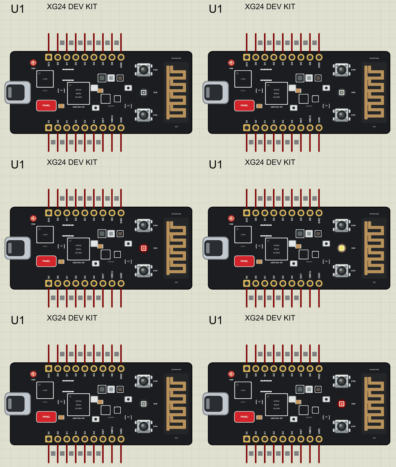
xG24 Dev Kit Library for Proteus
Latest version: V1.0 (November 2026, this tutorial)
Other new Arduino boards: UNO R4 WiFi · Nano ESP32 · UNO WiFi Rev2 · Nano 33 IoT · UNO Q · UNO R4 Minima · Nano Every · MKR WiFi 1010 · Nano RP2040 Connect · STM32 Black Pill · Nucleo-F401RE · STM32 Blue Pill · Teensy 4.1 · Arduino Due · Arduino Leonardo · Arduino Micro · BBC micro:bit V2 · GIGA R1 WiFi · MKR WAN 1310 · Nano 33 BLE Sense · XIAO nRF52840 Sense · RAK4631 WisBlock · Nano Matter · nRF52840 DK · nRF5340 DK · nRF9151 DK · nRF7002 DK · Nordic Thingy:53
RF modules: nRF24L01 · nRF24L01 PA LNA · CC1101 · RFM69HCW · HC-12 · 433MHz RF · XBee
Temperature and weather sensors: DHT11 / DHT22 · DS18B20 · BME280 · BMP280 · SHT31 · AHT20 · BME680 · MLX90614 · MAX6675
Helping Tools
- Laptop WiFi Monitor: a laptop on the Wi-Fi of your design: a browser, a TCP / UDP terminal and ping
- Mobile WiFi Monitor: a smartphone that opens the pages of your board and sends it commands
- Serial Monitor Advance: a serial terminal window for the UART of your board
For the demo we built a cold-chain parcel monitor: a smart label that rides inside a box of medicine. It knows when the box is closed and opened, raises an alarm when the load gets warmer than 8 C, when the box is tipped over or dropped, shows the state on its RGB LED and reports everything to a phone over Bluetooth LE.
NOTICE: Proteus has no EFR32MG24 model and no model of the kit's sensors, so our team has put a lot of effort into building this board ourselves: the pins, the RGB LED, the buttons, the sensors and Bluetooth LE are all our own model, and your sketch compiles with our free TEP Boards for Proteus add-on. Your feedback is the fuel that keeps us going, so please tell us what you think in the comments below. And if our free libraries help you, you can buy us a coffee. So, let's get started with the xG24 Dev Kit Library for Proteus:
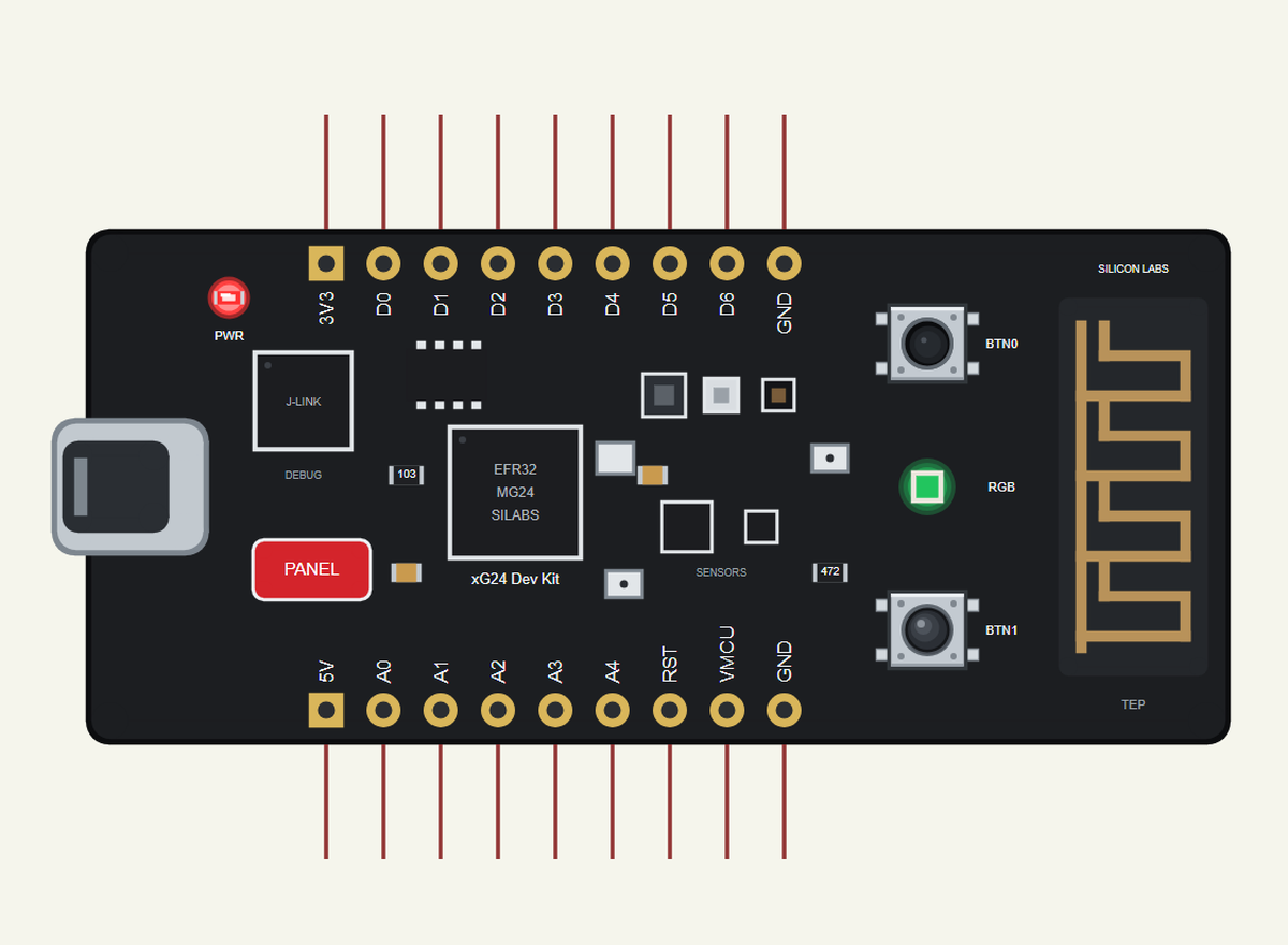
What is the xG24 Dev Kit?
The EFR32xG24 Dev Kit (xG24-DK2601B) is Silicon Labs' low-cost board for the EFR32MG24 wireless SoC. It is small and complete: an on-board J-Link debugger with a USB port and a virtual COM port, a set of sensors, an RGB LED, two push buttons, a printed 2.4 GHz antenna, breakout pads for your own parts, and a holder for a CR2032 coin cell, so the board can also run without a cable. The EFR32MG24 is an Arm Cortex-M33 with 1536 kB of flash and 256 kB of RAM, a 2.4 GHz radio for Bluetooth LE and 802.15.4 (Thread, Zigbee, Matter), and a Matrix Vector Processor that speeds up the maths of small neural networks.
| Part | The real xG24 Dev Kit | In the library |
|---|---|---|
| SoC | EFR32MG24: Arm Cortex-M33, Bluetooth LE, Thread, Zigbee, Matter | your Arduino sketch, ArduinoBLE |
| Temperature, humidity | Si7021 | Arduino_HS300x calls, from the Sensors window |
| Pressure | BMP384 | Arduino_LPS22HB calls |
| Ambient light | VEML6035 | Arduino_APDS9960 calls |
| Motion | ICM-20689 6-axis IMU | Arduino_BMI270_BMM150 calls: acceleration, rotation |
| Hall effect, microphones | Si7210, two ICS-43434 | drawn |
| On the board | RGB LED, BTN0, BTN1, J-Link with USB | all of them, animated; the USB opens the monitor |
| Memory | 1536 kB flash, 256 kB RAM | about 256 KB of flash, 8 KB of RAM |
Why the xG24 for Edge AI?
A sensor node that sends raw data over the radio all day empties its battery quickly. If the node can decide on the spot, for example "this vibration means the bearing is wearing out" or "this sound is glass breaking", it only has to send one short message. That decision is usually a small neural network, and most of its work is multiplying matrices. The xG24's accelerator does exactly that, faster and with much less energy than the main core, which is why the kit is supported by TinyML tools such as Edge Impulse and is a favourite in machine learning courses and research on battery-powered sensing.
Bluetooth LE, Thread, Zigbee and Matter
The EFR32MG24 has a multiprotocol radio. Bluetooth LE connects it to phones. Thread and Zigbee build mesh networks of many small devices in a home or a building, and Matter runs on top of Thread so that one light switch works with every smart-home system. A single chip that speaks all of them lets a product team choose the network late in the project, or even support two at once. In this library the board speaks Bluetooth LE to our phone; for a Matter project in Proteus, look at our Arduino Nano Matter Library for Proteus, which is built on the same family of Silicon Labs chips.
Where Is It Used?
Research teams use the xG24 Dev Kit for predictive maintenance (vibration on motors and pumps), keyword spotting and sound detection, indoor air and comfort studies, asset tracking and smart labels like our demo, and for comparing the energy of Bluetooth LE, Thread and Zigbee on the same hardware. The coin-cell holder makes it easy to leave a board running in a real place for days, and the breakout pads take extra sensors or a small display when the on-board ones are not enough.
A simulation cannot measure microamps or train a model, but it lets you build and test the whole logic of such a device first: the sensor readings, the thresholds, the alarms, the LED, the buttons and the Bluetooth service. When the logic works in the Proteus simulation, moving the sketch to the real kit is much quicker.
How Bluetooth LE Notifications Work
A Bluetooth LE device offers services, and each service holds characteristics, small values with a UUID that a phone can read. Our parcel monitor has one service with five characteristics: the temperature, the humidity, the tilt, the number of alarms and the status. A phone subscribes once, and the board sends a notification every time a value changes. Our Mobile WiFi Monitor is that phone in Proteus.
Features of the xG24 Dev Kit Library for Proteus
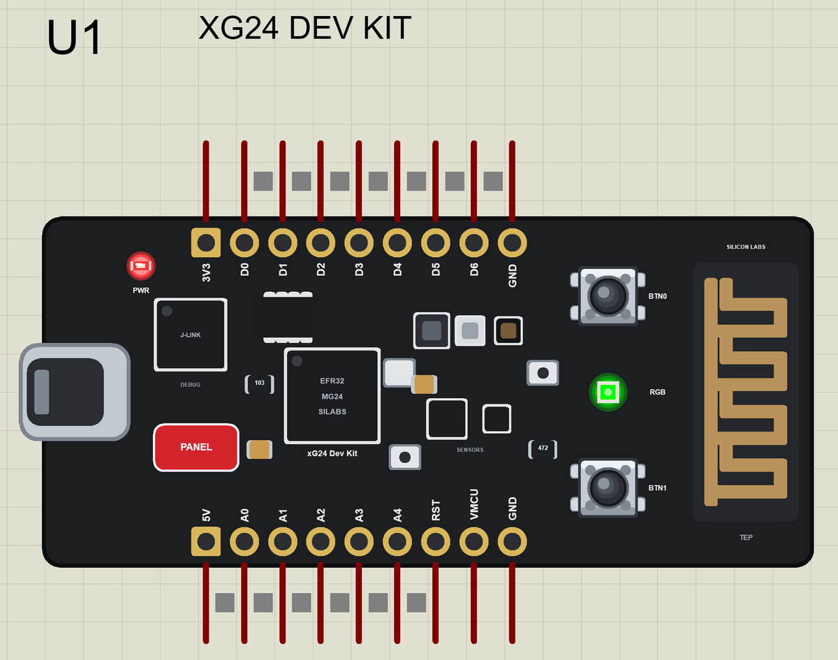
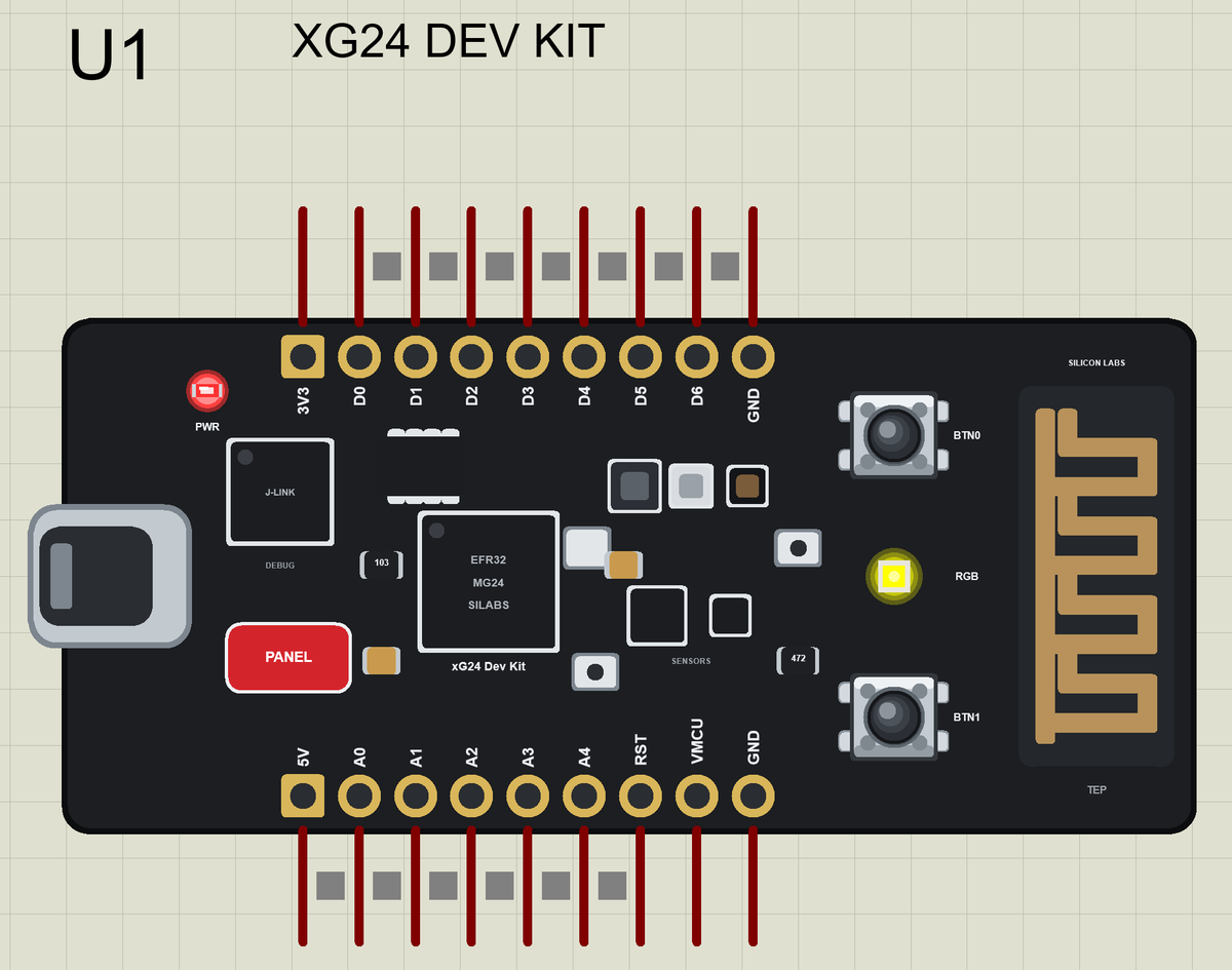
- The board as it looks: the black PCB with the USB-C port, the J-Link debugger, the EFR32MG24, the sensors, the RGB LED, BTN0 and BTN1, the printed antenna, the breakout pads and the PANEL pad, drawn compact, with our small TEP signature.
- Your sketch: a .hex for "Silicon Labs xG24 Dev Kit (TEP Proteus)" with the Silicon Labs Arduino core's pin names: D0 to D6, A0 to A4, LEDR, LEDG, LEDB, BTN0 and BTN1.
- The sensors: temperature, humidity, pressure, light and motion through the board package's sensor libraries, set from the Sensors window.
- Bluetooth LE: ArduinoBLE, with our phone as the central: scan, connect, read, write and notifications.
- A real RGB LED and buttons: the LED lights when LOW, as on the real kit, and glows in the mixed colour; the buttons are clicked on the board.
- A complete package: about 3.3 MB with the part, the add-on, the phone and the demo, without the source code of the models.
The xG24 Dev Kit in Proteus Simulation
Search XG24 in Pick Devices; the device is in TEPXG24DK.LIB (Microprocessor ICs, Bluetooth Boards), with the prefix U. Click the USB-C port for the serial monitor and the PANEL pad for the Sensors window. The sensor calls are the same as on our Arduino Nano 33 BLE Sense Library for Proteus, so a sketch for one moves to the other easily.
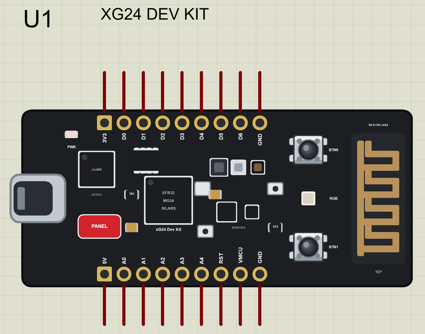
The Pins
| Pins | What the library does with them |
|---|---|
| D0 to D6 | GPIO, PWM with analogWrite, attachInterrupt; D0 MOSI, D1 MISO, D2 SCK, D3 SS |
| D4, D5 | Serial1 TX and RX, or GPIO |
| D6, A4 | SDA and SCL: Wire, the I2C bus |
| A0 to A3 | analogRead 0 to 1023 for 0 to 3.3 V, or GPIO |
| LEDR, LEDG, LEDB | the RGB LED (12, 13, 14), lit when LOW |
| BTN0, BTN1 | the buttons (15, 16), LOW when pressed |
| 3V3, 5V, GND, RST | the supply and the reset |
The Sensors Window
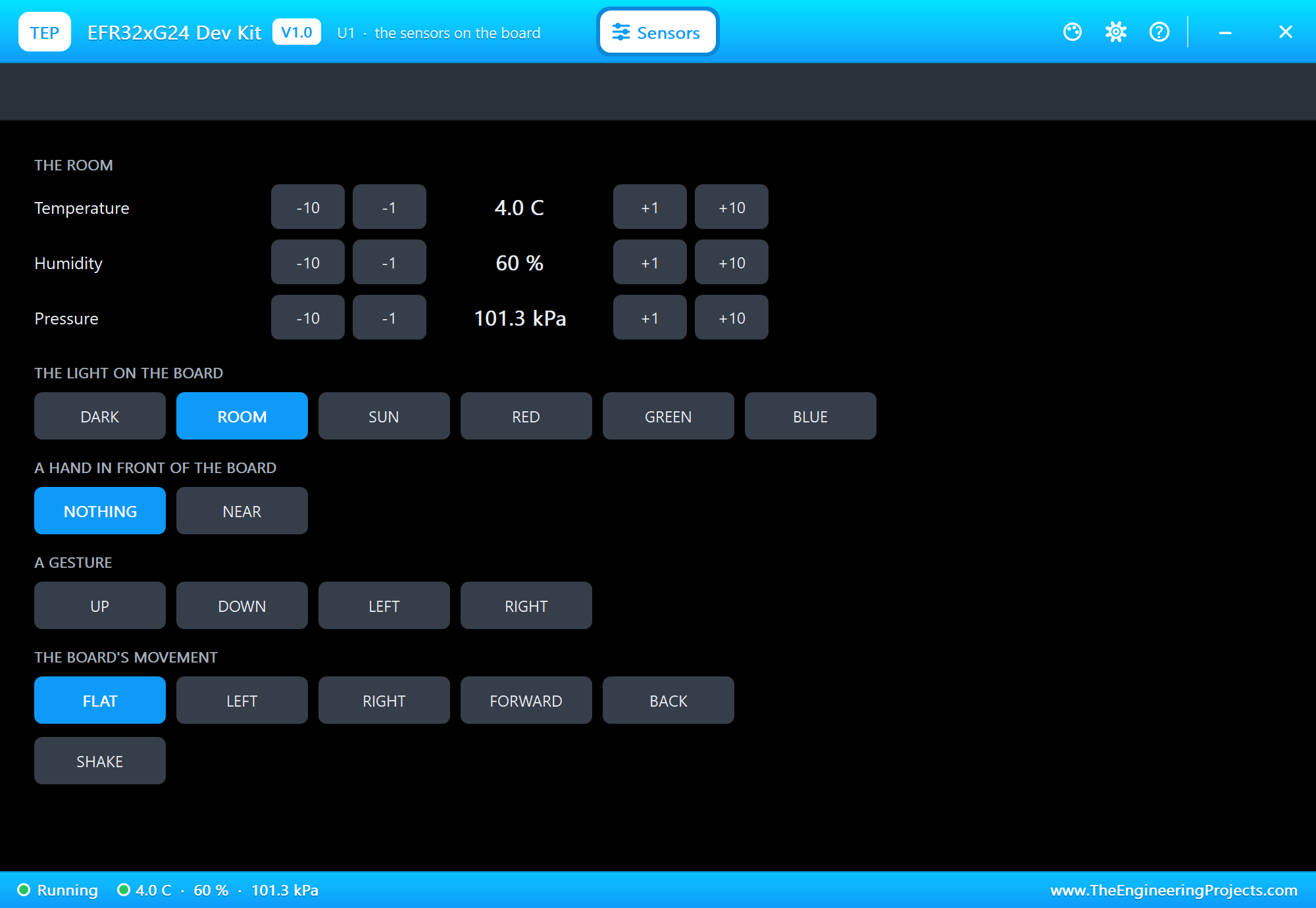
The PANEL pad opens the Sensors window, where you set the world around the board while the simulation runs: the temperature, the humidity and the pressure with -10, -1, +1 and +10 buttons, the light (DARK, ROOM, SUN or a colour), a tilt and a SHAKE. The sketch reads the new values on its next call.
Download xG24 Dev Kit Library for Proteus
Click the button below to download xG24-Dev-Kit-Library-for-Proteus-v1.0.zip (about 3.3 MB, without the source code of the models):
xG24 Dev Kit Library for Proteus V1.0- README.txt: installation, the demo, the pins, the properties, troubleshooting and the limits.
- Proteus Library Files:
TEPXG24DK.LIBand the phone and laptop:TEPMOBILE.LIBandTEPLAPTOP.LIB. - Proteus Model Files:
TEPNET.DLL. - Arduino Code: the demo sketch and the TEP Boards for Proteus add-on 1.65.0, with ArduinoBLE and the four sensor libraries.
- Proteus Simulation: the demo project, its HEX file and a copy of the DLL.
No Proteus yet? Read How to Download and Install Proteus 7 and 8. New to libraries? Follow How to Install a New Library in Proteus.
How to Install xG24 Dev Kit Library for Proteus
- Close Proteus and extract the whole zip file, for example to your Desktop.
- Copy the files from Proteus Library Files into the LIBRARY folder of Proteus.
- Copy
TEPNET.DLLfrom Proteus Model Files into the MODELS folder, replacing an older one. - Delete
TEPXG24DK.IDXfrom the LIBRARY folder if it is there. - For your own sketches, copy Arduino Code\TEP Boards for Proteus\hardware into your Arduino sketchbook (Documents\Arduino) and restart the Arduino IDE; the board is Silicon Labs xG24 Dev Kit (TEP Proteus). ArduinoBLE and the sensor libraries are in the add-on: nothing else to install.
- Start Proteus, press P and search for XG24.
Demo: a Cold-Chain Parcel Monitor in Simulation
Vaccines, insulin and many foods must stay between 2 and 8 C from the factory to the patient. A broken cold chain is invisible from the outside of a box, so shippers put small loggers inside. Ours does more than log: it watches the temperature, the tilt and the shocks, knows when the box is opened, and tells the person who opens it with one look at the LED or one tap on a phone.
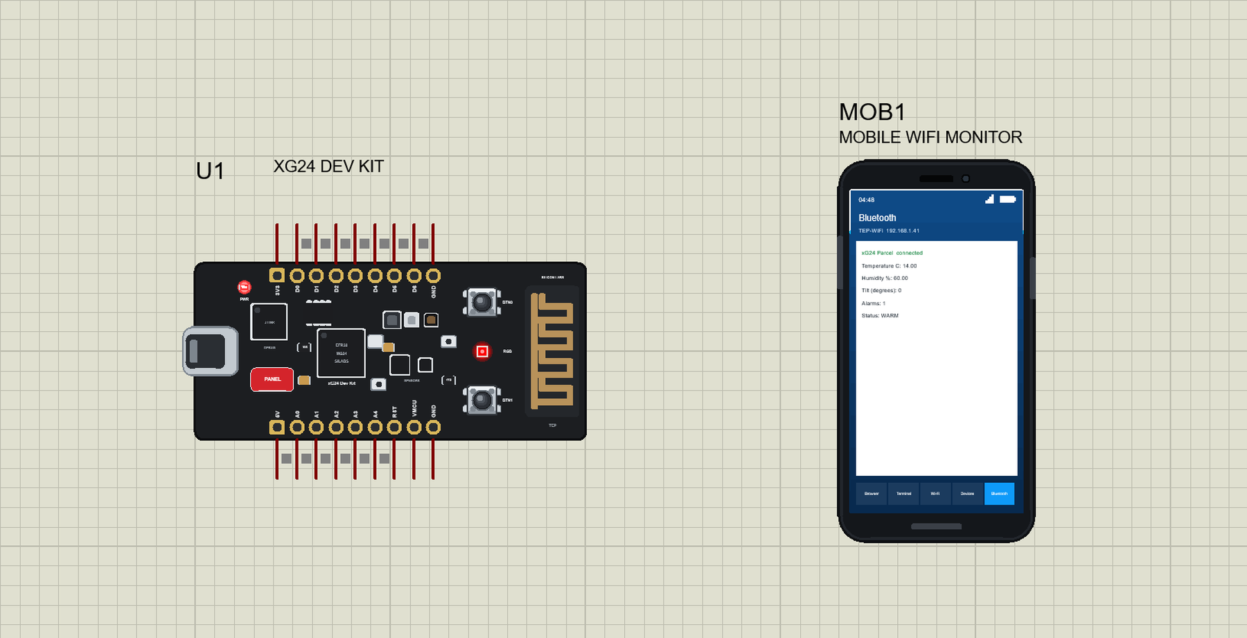
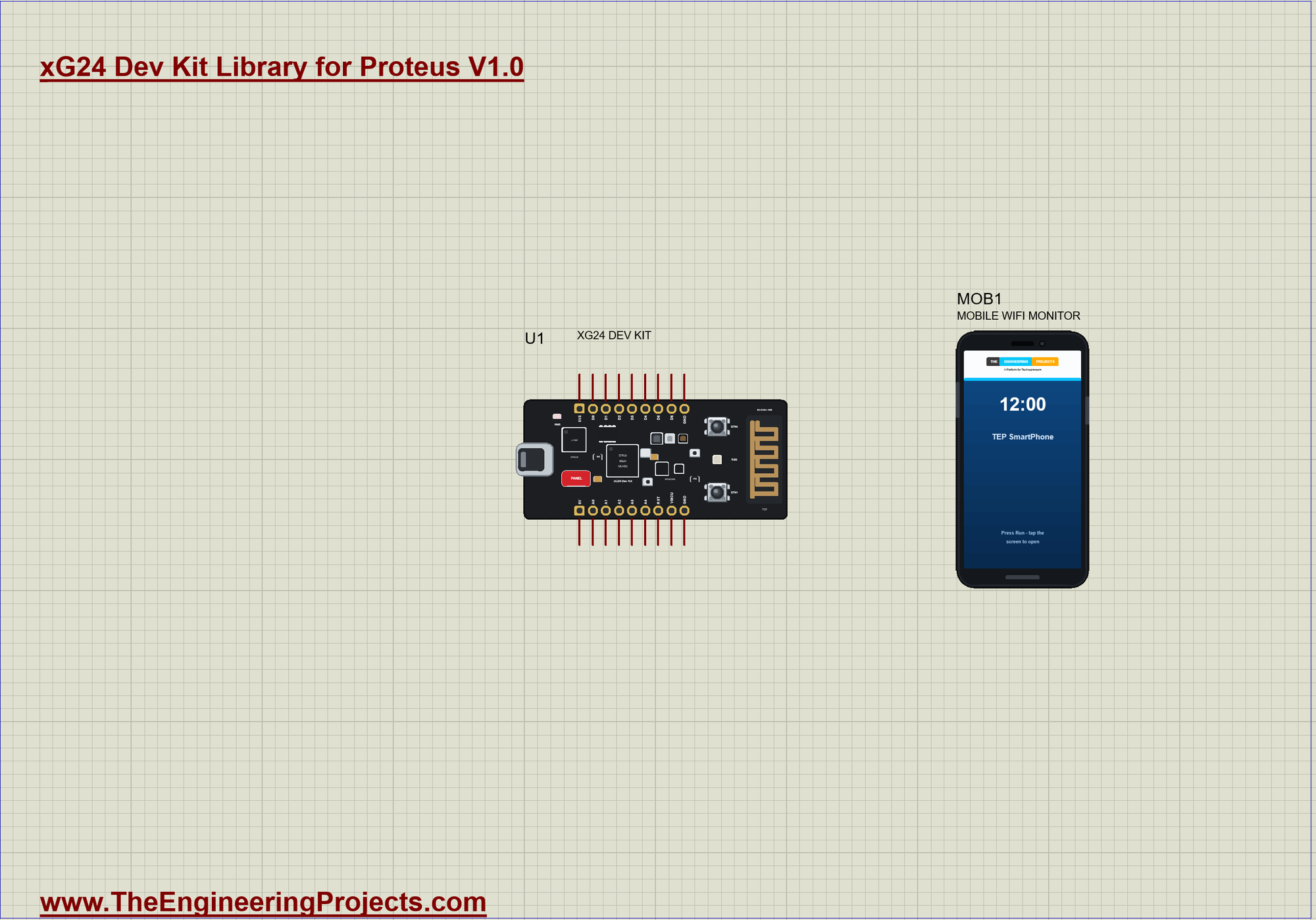
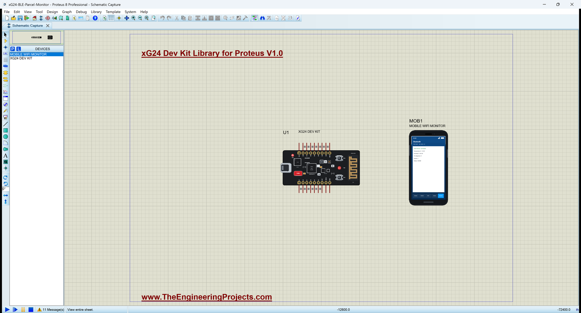
Open xG24-BLE-Parcel-Monitor.pdsprj. U1 runs xG24_Parcel_Monitor.hex, and MOB1 is the phone, whose Bluetooth app connects to the board. There are no wires on this sheet. The serial monitor is the same window as our TEP Serial Monitor Advance for Proteus.
The Box Closes
Inside a closed box it is dark, so the monitor waits until the light drops below 20 and then arms itself. From that moment, light means the box has been opened:
  if (!armed) {
    if (light < DARK_LIGHT) {
      armed = true;
      minC = maxC = tempC;
      setStatus("OK");
      Serial.println(F(">> Box closed - monitoring armed"));
      showLed();
    }
    return;
  }
Three Alarms, Raised Once
Each condition raises its alarm only when it starts, not on every reading, so a warm box gives one WARM alarm and not one every half second:
  const bool nowWarm = tempC > WARM_C, nowTipped = tilt > TIP_DEG, nowOpened = light > OPEN_LIGHT;
  if (nowWarm && !warm) alarm("WARM", String(tempC, 1) + " C");
  if (nowTipped && !tipped) alarm("TIPPED", String(tilt) + " deg");
  if (nowOpened && !opened) alarm("BOX OPENED", "light " + String(light));
Counting Shocks
At rest the accelerometer reads 1 g. A drop or a hard knock adds a short burst of acceleration, so the sketch raises SHOCK above 1.8 g and then waits one second, so that one knock is one alarm:
void watchShock() {
  if (!armed || !IMU.accelerationAvailable()) return;
  float x, y, z;
  IMU.readAcceleration(x, y, z);
  const float g = sqrt(x * x + y * y + z * z);
  if (g > SHOCK_G && millis() >= calmUntil) {               // one shock, then a second of calm before the next one counts
    calmUntil = millis() + CALM_MS;
    shocks++;
    alarm("SHOCK", String(g, 2) + " g");
  }
}
The RGB LED
The kit's LED lights when the pin is LOW. Four colours tell the whole story: blue while the box is open before the trip, green when all is good, red for a new alarm, and yellow when the alarm has been acknowledged with BTN0 but the problem is still there:
void showLed() {
  if (!armed) rgb(false, false, true);                      // blue: waiting for the box to close
  else if (unacked) rgb(true, false, false);                // red: a new alarm
  else if (bad()) rgb(true, true, false);                   // yellow: acknowledged, still not good
  else rgb(false, true, false);                             // green: all good
}
The Bluetooth Service
The service holds the five values, each with BLERead | BLENotify; the temperature and the humidity use the standard UUIDs 0x2A6E and 0x2A6F, so any Bluetooth app understands them:
BLEService parcelService("19B10050-E8F2-537E-4F6C-D104768A1214");
BLEFloatCharacteristic tempChar("2A6E", BLERead | BLENotify);
BLEFloatCharacteristic humChar("2A6F", BLERead | BLENotify);
BLEIntCharacteristic tiltChar("19B10051-E8F2-537E-4F6C-D104768A1214", BLERead | BLENotify);
BLEIntCharacteristic alarmsChar("19B10052-E8F2-537E-4F6C-D104768A1214", BLERead | BLENotify);
BLEStringCharacteristic statusChar("19B10053-E8F2-537E-4F6C-D104768A1214", BLERead | BLENotify, 12);
Run the Simulation
Press Run. The board starts advertising as "xG24 Parcel" and waits for the box to close, with the RGB LED blue:
xG24 Dev Kit Cold-Chain Parcel Monitor - The Engineering Projects
Advertising as "xG24 Parcel", address 34:25:B4:26:A0:00:01
BTN0 = acknowledge an alarm, BTN1 = trip report
Waiting for the box to close (the light below 20)
Box: 4.0 C  60 %  1013.0 hPa  light 270  tilt 0 deg  WAITING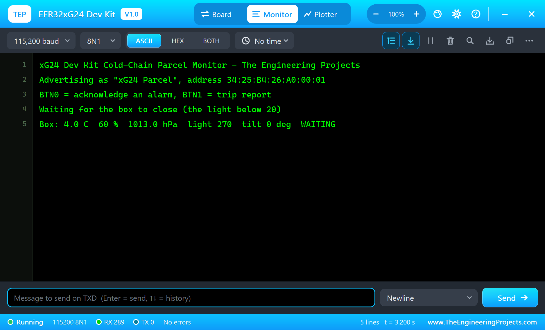
Connect the Phone and Close the Box
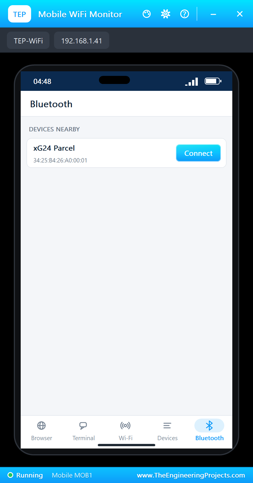
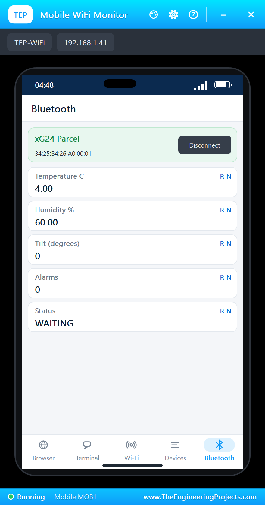
Click the phone, open its Bluetooth app and press SCAN, then Connect to "xG24 Parcel". Now click DARK in the Sensors window: the box is closed, the monitor arms itself and the LED turns green:
The Cold Chain Breaks
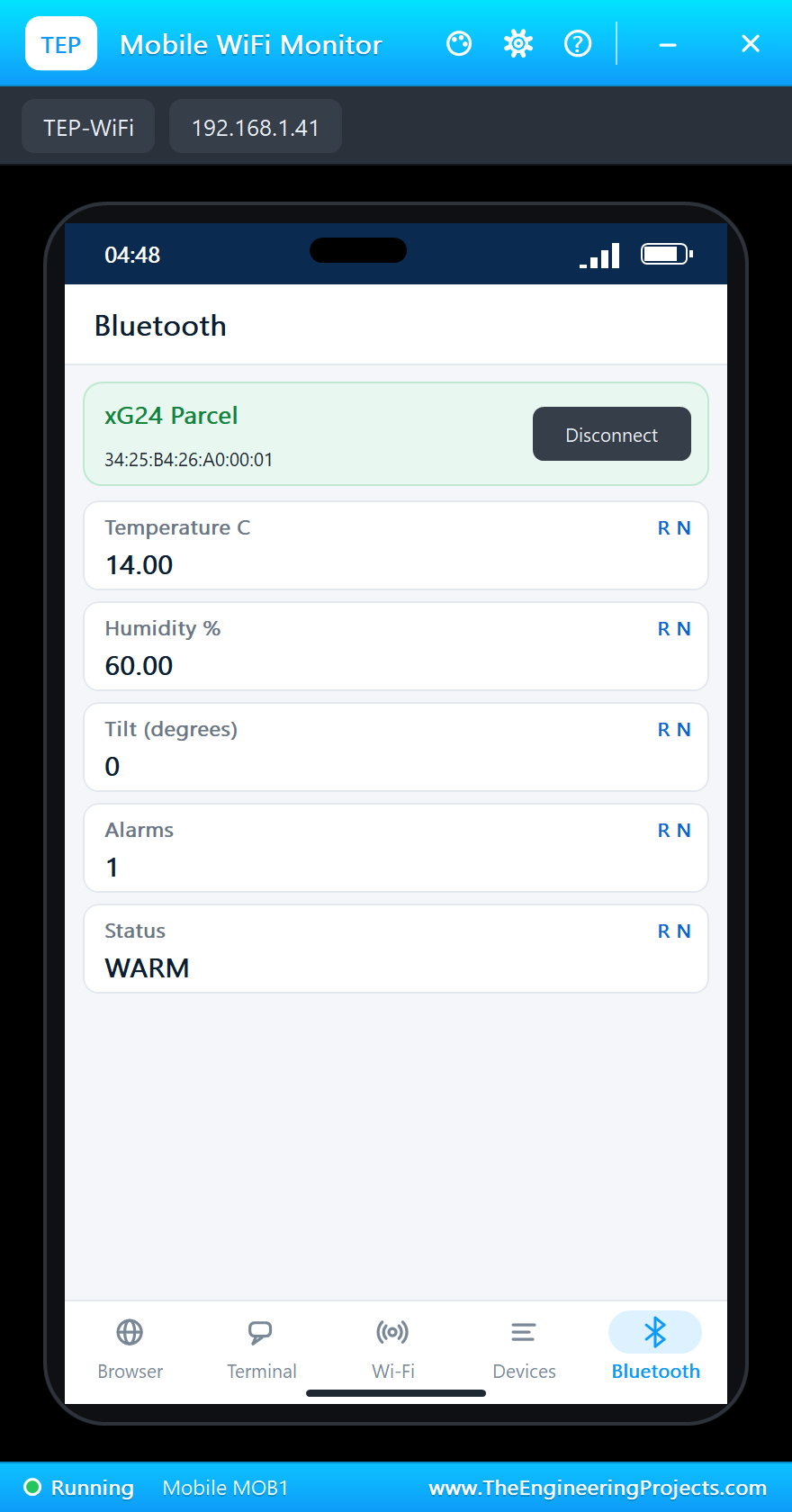
Click +10 next to the temperature. The load jumps from 4 C to 14 C, well above 8 C: WARM, the LED turns red and the phone shows the alarm. Press BTN0 to acknowledge it: the LED turns yellow, because the box is still too warm. Click -10 and it is back to normal and green:
>> Box closed - monitoring armed
Box: 4.0 C  60 %  1013.0 hPa  light 6  tilt 0 deg  OK
>> ALARM: WARM (14.0 C)
Box: 14.0 C  60 %  1013.0 hPa  light 6  tilt 0 deg  WARM
>> BTN0: alarm acknowledged (still not good)
>> Back to normal
Box: 4.0 C  60 %  1013.0 hPa  light 6  tilt 0 deg  OK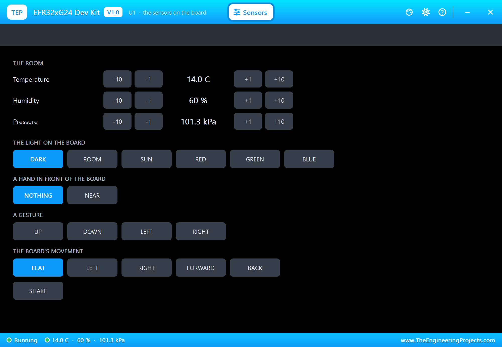
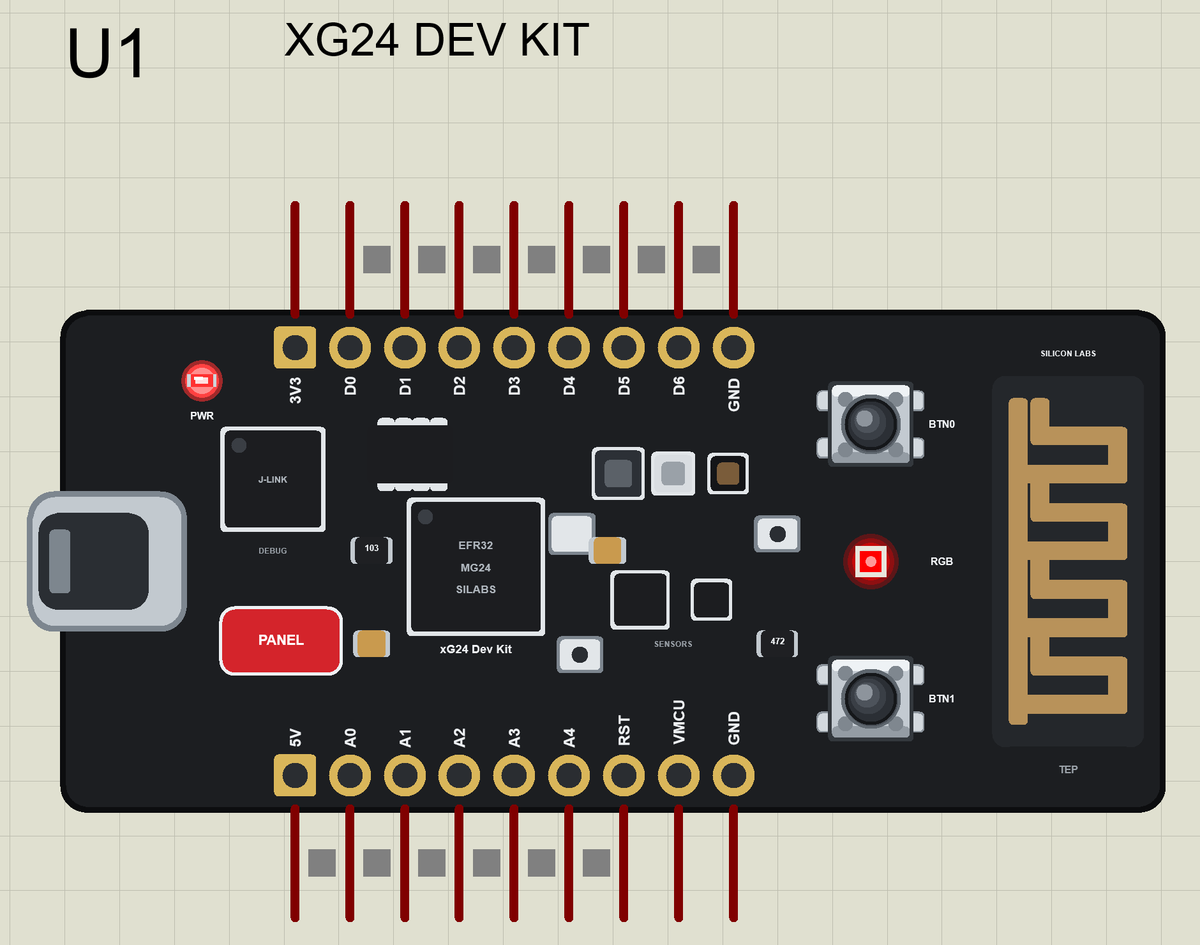
Here is the complete circuit while the simulation runs:
Rough Handling
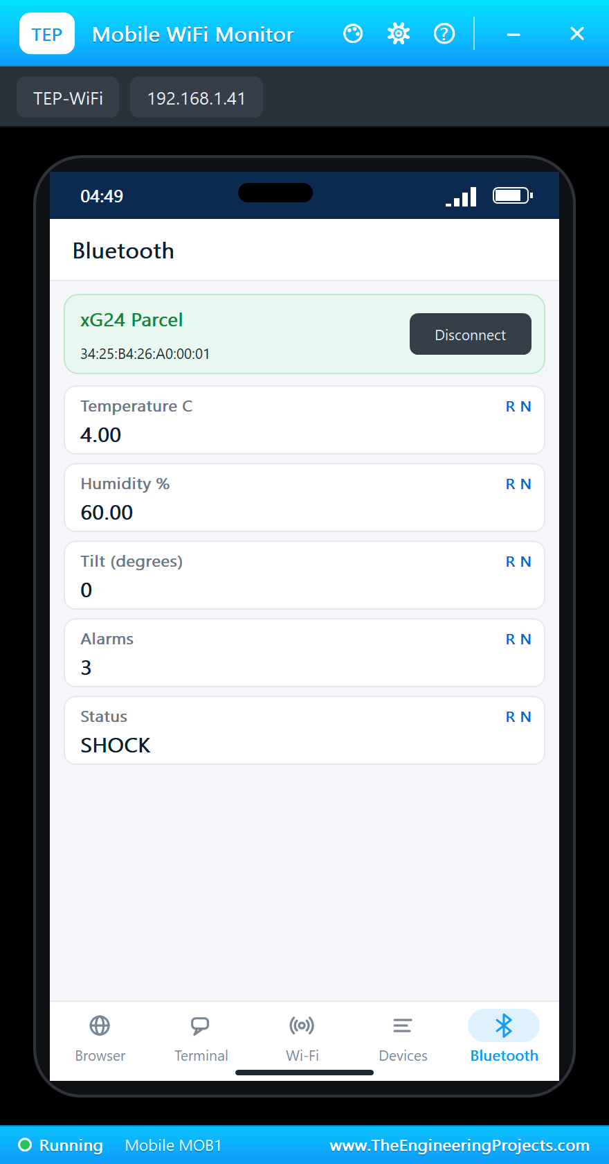
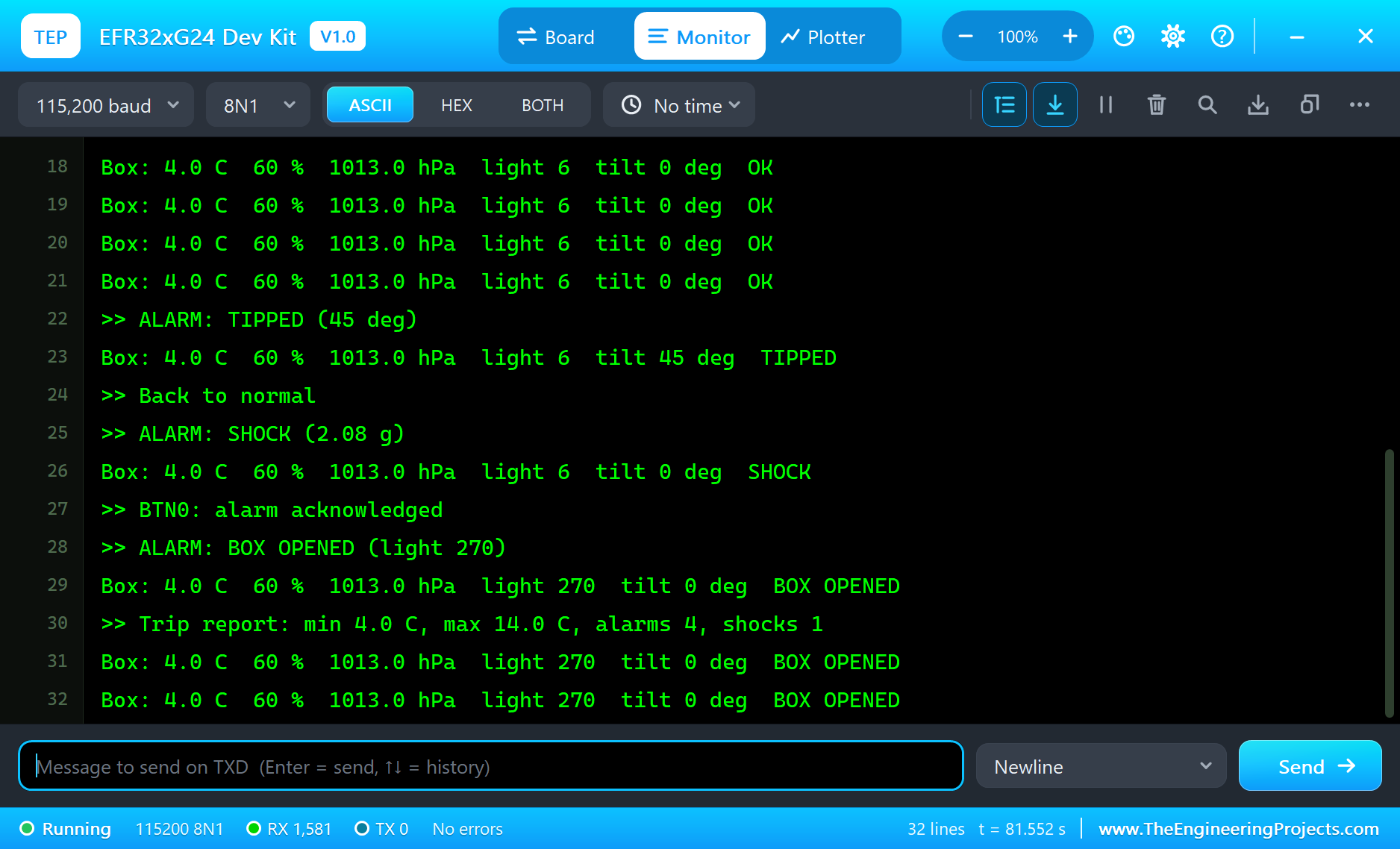
Click LEFT in the movement row: the box leans 45 degrees and the monitor raises TIPPED; FLAT puts it back. Then click SHAKE: SHOCK, with the peak acceleration. BTN0 acknowledges both:
>> ALARM: TIPPED (45 deg)
Box: 4.0 C  60 %  1013.0 hPa  light 6  tilt 45 deg  TIPPED
>> Back to normal
>> ALARM: SHOCK (2.08 g)
Box: 4.0 C  60 %  1013.0 hPa  light 6  tilt 0 deg  SHOCK
>> BTN0: alarm acknowledged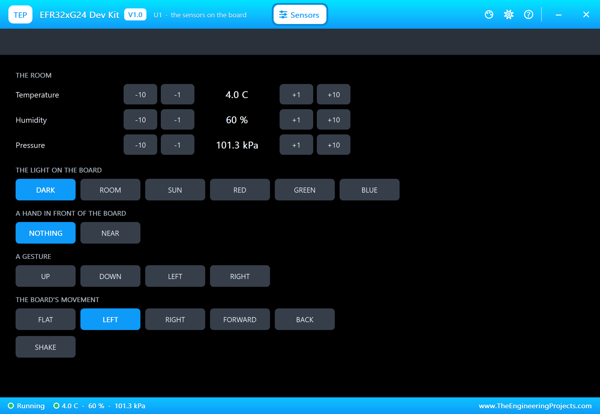
The Box Is Opened
Click ROOM in the light row: the box is opened, the monitor raises BOX OPENED and the LED turns red. Press BTN1 for the trip report:
>> ALARM: BOX OPENED (light 270)
Box: 4.0 C  60 %  1013.0 hPa  light 270  tilt 0 deg  BOX OPENED
>> Trip report: min 4.0 C, max 14.0 C, alarms 4, shocks 1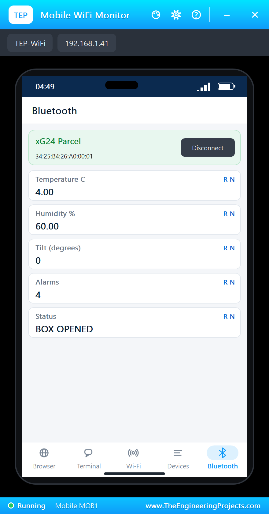
Try It Yourself
- Change
WARM_Cto 25 for a chocolate shipment, and add a COLD alarm below 2 C for vaccines. - Make the LED blink red instead of steady red, so a new alarm is easier to see.
- Count how many minutes the load spent above 8 C and add it to the trip report.
- Add a writable characteristic so the phone can acknowledge the alarms instead of BTN0.
Ideas to Extend the Monitor
- Keep a log of every reading in the SPI flash and send it to the phone when it connects at the destination.
- Use the pressure to notice an air freight leg: the cabin pressure is lower than on the ground.
- Train a small model on the IMU data to tell a drop from a truck's normal vibration.
- Send the alarms over Thread or Zigbee to a gateway in the warehouse instead of a phone.
Your Own Sketches
Write the sketch in the Arduino IDE with the board Silicon Labs xG24 Dev Kit (TEP Proteus), use Sketch > Export Compiled Binary and set the part's PROGRAM property to the .hex. The pin names are the ones of the Silicon Labs Arduino core, so the same sketch structure works on the real kit; there the sensors need their own libraries (for the Si7021, the BMP384, the VEML6035 and the ICM-20689) instead of the ones the simulation answers.
Things to Know Before Using a Real xG24 Dev Kit
- 3.3 V logic: the breakout pads are not 5 V tolerant.
- Sensor power: on the real kit the sensors and the microphones have enable pins, so switch them on before you read.
- Coin cell or USB: the board can run from a CR2032 for field tests; the debugger and the virtual COM port need the USB.
- The radio needs room: keep the printed antenna away from metal and from your fingers.
- Matter needs more: a real Matter device also needs a commissioning flow and certified credentials.
Properties of the xG24 Dev Kit
| Property | What it does |
|---|---|
| PROGRAM | the sketch: a .hex from TEP Boards for Proteus (board "Silicon Labs xG24 Dev Kit") |
| MONITOR, BAUD, AUTOOPEN | the built-in serial monitor: on, its baud rate (115200), open at Run |
| TEMPERATURE, HUMIDITY, PRESSURE | the world at Run (the demo: 4 C, 60 %, 101.3 kPa) |
Troubleshooting
- The phone finds nothing: press SCAN after "Advertising as" is printed; the sketch must call
BLE.advertise(). - The demo stays blue: it waits for the box to close; click DARK in the Sensors window.
- A sensor reads 0: call its
begin()first. - The LED looks inverted: on this kit it lights when the pin is LOW.
- A number goes wrong above 32767: int is 16 bits in the simulation - use long.
Limitations of the Simulation
- Bluetooth LE works as a peripheral only. Thread, Zigbee and Matter are not modelled.
- The Hall-effect sensor, the microphones, the AI/ML accelerator, the SPI flash and the coin-cell power are drawn, not modelled.
- Your sketch gets 8 KB of RAM in the simulation, and int is 16 bits there.
- EFR32, xG24 and Silicon Labs are names of Silicon Laboratories Inc., Arduino of Arduino, and the Bluetooth word mark belongs to Bluetooth SIG; this library is not made or endorsed by them or by Labcenter.
- Tested in Proteus 8.5 in November 2026 (the demo as shipped, about 82 s of simulation). Proteus 7 is not supported.
So, that was all about the xG24 Dev Kit Library for Proteus. I hope it helps you try your Bluetooth sensor ideas in a simulation before you buy the kit - the sensors, the alarms, the LED, the buttons and the phone, all on one sheet. If you have any questions, ask in the comments and I will help you out. Till the next tutorial, take care and have fun!