Pulse Width Modulation using 555 Timer in Proteus

Hello Engineers! Welcome to the board. We hope you are having a good day. In this tutorial, we teach you about Pulse Width Modulation. We'll discuss some important points about the topic. Let's have a look at the Topics of the tutorial:
  1. What is Pulse Width Modulation?
  2. What is 555 Timer?
  3. how does 555 Timer is used in the Pulse Width modulation circuit?
  4. How do we design the circuit of Pulse Width Modulation in Proteus ISIS?
In addition, you will have some useful information bout Pulse Width Modulator in DID YOU KNOW section.
Where To Buy?
No.ComponentsDistributorLink To Buy
1555 TimerAmazonBuy Now
2LEDsAmazonBuy Now
3ResistorAmazonBuy Now

Pulse Width Modulation

Pulse width Modulation is a useful technique in the world of Modern Electronics. Let's have a look at the information about Pulse Width Modulation.

Abbreviation of Pulse Width Modulation

The Abbreviation of the Pulse Width Modulation technique is PWM.

Definition of Pulse Width Modulation

We define the pulse Width Modulation as:
"The Pulse Width Modulation is the technique  in the electronics to control the power given to the analogue devices through which the average power delivered by the electrical signal is reduced due to division of the signals into discrete parts."
The Pulse Width Modulation is important to the inertial load devices such as motors because in these devices the change is slow due to their inertial ability and the Pulse Width Modulator has enough time to control the device.

Example of PWM

We know that in the bulb that we use in our daily life, the AC Power changes its direction from positive to negative cycle and vise versa. The frequency through which the cycle change decides the brightness of the bulb. Consider the example of the circuit in which the LED is connected to the power. The Power connection lightens the LED. When the switch between the power source and the bulb is close, the power is transmitted to the bulb and the brightness is observed. The opening and the closing of the switch can be controlled through the Pulse Width Modulation. The more is the duty cycle of the Pulse width, the more rapidly it opens and closes the switch and hence the brightness of the bulb is more and vise versa. hence we can conclude that by controlling the pulse width we are controlling the opening and closing of the switch and through which we are controlling the brightness of the bulb.  

DID YOU KNOW????????????

"The Pulse Width Modulation technique is also called as the Pulse Duration Modulation or PDM. It is because this technique works with the duration of the cycle of the circuit. "

555 Timer in Pulse Width Modulation

Prior to start the work of 555 Timer in Pulse Width Modulator, we must clear some important concepts about the 555 Timer device. Let's have a glance on the points.

Definition of 555 Timer

The 555 Timer was termed as the SE NE555 Timers. Another Type of the 555 Timer is SE555 Timer. These were first invented by "Signetic Corporation" . We define the 555 Timer as:
"The 555 Timer is an 8 pin Integrated Circuit that generates accurate timing pulse. The designing of the 555 timer is done by collectively arranging the electrical and electronic components such as resistors, transistors, diodes and Flip Flops."
These are monolithic Timing circuits that are designed to provide stable time delay and oscillations. These are highly reliable and low in cost.

Pin out of 555 Timer

There are 8 pins of 555 Timer and each pin has its own function and operation. For the best concept, we have designed a table for each pin given below:
Pin Number Pin Name Description
1 Ground This pin is labeled as GND and used to supply the 0 voltage.
2 Trigger When the Time interval starts, the output remains low when this pin is high and vise versa.
3 Output This is the output pin.
4 Reset This pin overrides the Trigger pin and that overrides the Threshold. It is connected with Vcc if not used.
5 Control It controls the Pulse Width and the level of threshold and Trigger.
6 Threshold Hen the voltage is applied at this pin, it acts in the contrast to the voltage.
7 Discharge This pin is an open-collector output. During the intervals, this pin is used to discharge the capacitor.
8 Supply This is the power supply pin. The input of power is taken against the Ground pin.

DID YOU KNWO???????????

"We use the counter instrument in the Proteus to count the Pulse Width Modulation of the circuit using 555 Timer."

Implementation of PWM using 555 Timer in Proteus ISIS

To implement the Pulse Width Modulation using 555 Timer, we are using the simulation in Proteus ISIS. To Implement the 555 Timer PWM  just follow the simple steps given next:
  • Fire up your Proteus Software.
  • Choose the following components:
  1. 555 Timer
  2. 1N4148 Diode
  3. 3005P-1-502 Variable Resistor
  4. DC Power Supply
  5. Resistor
  6. Counter
  7. Oscilloscope
  • Fix first five components from the "Pick Library" at the working area.
  • Change the values of Resistor, Capacitors and variable Resistors according to the table given below:
    Component Values
    Resistor 1k ohm
    Variable Resistor 50k ohm
    Capacitor 1 10nf
    Capacitor? 1uF
    DC Power source 10V
     
  • Go to Terminal mode>Ground and set it at the end of the circuit.
  • Connect the components through the connecting wires according to the image given next:
  • To get the counting of the output, go to virtual Instrument Mode and choose the counter.
  • Go to Virtual instrument Mode and select the Oscilloscope.
  • Connect the counter with any terminal of the Oscilloscope.
  • Join both the instruments with pin 3 of 555 Timer.
  • Pop the play button and simulate the circuit.
  • Change the values of voltages and the frequency according to need.
  • We observe that the Oscilloscope shows us the width as:
Thus, Today we saw what is the pule Width Modulation, learned some important concepts about the 555 Timer, got some important concepts about Pulse Width Modulation using the 555 Timer and saw the simulation by the mean of Proteus ISIS. If you found it useful, give us your important feedback in the comment section.

Metal Detector using 555 Timer in Proteus

Hello Pupils! I welcome you to the board. I hope you are fine. In today's tutorial, we will design a project Metal Detector using 555 Timer in Proteus ISIS. All of us perceive the situations when at the public places such as on airports or in shopping malls where sharp metallic objects such as a knife or illegal guns or even a nail cutter are not allowed, there are walkthrough gates at every entrance so that any person with the forbidden material when passes through the gate, the alarming buzzer automatically switched on. This happened because the walkthrough gates have the Metal Detector circuit in them that works immediately when such a situation occurs. In this session, we'll learn:
  1. What are Metal Detectors?
  2. How does the 555 Timer collaborate with the circuit of Metal Detector?
  3. How does the circuit of the 555 Timer Metal Detector works?
  4. How can we implement the circuit of 555 Timer Metal Detector in Proteus?
In addition, you will also have some useful pieces of information in DID YOU KNOW Sections.
Where To Buy?
No.ComponentsDistributorLink To Buy
1555 TimerAmazonBuy Now
2LEDsAmazonBuy Now
3ResistorAmazonBuy Now

NE555 Timer Metal Detectors

Metal Detectors became the one of the necessary devices for many public Places either it is park or bank, airport or any supermarket. It is because they play a vital role in the maintenance of security. Most of the metal detectors We define the Metal Detector as:
"The Metal detectors are the specialized NE555 Timer gadgets that detect the presence of the metals when the metals enters in the range of Metal Detector Circuits."
The NE555 Timer Metal Detectors does not only have the application i the field of security but they are also used in a variety of situations. The NE555 Timer Metal Detector can be categorized into three basic Families:
  1. Very Low Frequency Detectors.
  2. Pulse Induction Detectors.
  3. Metal Detectors for specific Purpose.

DID YOU KNOW??????????????????????

"1960 was the year in which the 1st Metal Detector was established using simple devices in industrial and Mineral Prospecting. "
There are many kinds of NE555 Timer Metal Detectors that are used for different operations some of them are listed below:
  1. Diagnostic Purposes.
  2. Detecting myriad of foreign objects.
  3. Finding the presence of bullets.
  4. Detecting the intraocular metallic fragments.
  5. Finding Swallowed coins.

Working of NE555 Timer Metal Detector

When we talk about the working of the NE555 Timer Metal Detector, we must have a clear idea about the following concepts:
  1. Inductance
  2. NE555 Timer operational system

Inductance in NE555 Timer Metal Detector

Let's recall the idea of Inductance that we are learning from our physics class:
"The Inductance, in electromagnetism and electronics, is the ability of a conductor of electricity to negate the change in the electric current that is flowing through it. This flow of electric current produces a magnetic field around that electrical conductor."
In the NE555 Timer Metal Detector circuit, we use an inductor that senses the presence of the Metal near to it. More close a Metal Detector to it, the more electric field lines are produced and hence the speaker gives the sound more loudly indicating the distance between the NE555 Timer Metal Detector and the metal's distance. We denote the Inductance through "L". Hence the formula to find the Inductance through any Conductor can be find through: Inductance= Magnetic Flux of Current/Current.

DID YOU KNOW ???

"There are some Metal Detectors that are used to find the treasure or ancient metals underground. They are so powerful that they can detect the Metal many feet away.  Thus, many people have a life changing search due to these useful instruments."

NE555 Timer

NE555 Timers belongs to the Family of 555 Timers Integrated Circuits. These are highly utilitarian circuits that are considered as one of the most used Integrated Circuits in the world of Electronics. We introduce the NE555 Timer as:
"NE555 Timer Circuit is the widely used Integrated Circuit having 8 pins and used to have the output that have a uniform pulses that can be set according to need."
The 555 Timers are used to have a variety of pulses that depends upon the arrangement of the devices connected to their Pins. There are three kinds of NE555 Timer modes:
  1. Monostable Mode.
  2. Astable Mode.
  3. Bistable Mode.

Operations in the NE555 Timer Metal Detector Circuit

  • When we examine the Circuit of NE555 Timer Metal Detector, we find these operations:
  • The power of all the components is the Direct current that is provided by the battery.
  • This power enters the NE555 Timer circuit that produces the uniform Timer-based Pulse at its output pin.
  • This Pulse enters the resistor that controls the flow of current through the main Metal Detector circuit.
  • The Resistor passes this current to the Inductor. The Inductance of the inductor is the basic criteria of distance measurement.
  • As in Proteus, it is not possible to show the Movement of a Metal, so the value of the inductance represents the number of electric field lines around the NE555 Timer Metal Detector circuit. More is the Inductance, more numbers of lines passing through the inductor and hence it is assumed that metal is more near to the circuit. 
  • The DC current then passes through the speaker according to the strength of the electric field lines and hence we found the faint or hard sound.
[PostWiidget4]

Circuit design of 555 Timer Metal Detector in Proteus

  • Power up your Proteus Software.
  • Choose the following components from the Pick Library button "P".

Components Required

  1. NE555 Timer
  2. Inductor
  3. Capacitor
  4. Resistor
  5. Speaker
  • Take all the Components from the left section and arrange all of them on working screen according to the diagram given below:
 
  • Now, Change the values of some of the components one after the other by double clicking the components.
  • Inductor= 150mH, Capacitor 1=2.2uF,Capacitor 2=2.2uF,Capacitor 3 10uF, Resistor= 47k Ohm, Battery=9V.
  •  Connect the circuit components with the help of connecting wire so our circuit look like this:
  • As soon as the Circuit is simulated by hitting the Play button, the user sense a sound or buzzer from the circuit.
  • If you heard it then cool, otherwise look at your circuit once again.

Task

Change the value of inductor to 300micro Farad and more to hear the louder sound.
Hence today, we saw what are NE555 Timer Metal Detector, How do they are classified, how does the circuit of 555 Metal detector works and how can we design its circuit using simple devices in Proteus ISIS. Stay with us for more projects.

Police Siren Project using 555 Timer in Proteus

Hey Geeks! Welcome to The Engineering Projects. We hope you are having a reproductive day. We know that sirens are the special sounds that are the symbol that something unusual is occurring or about to occur. You may have experienced the Siren of the Walkthrough Gates at the airport when a person having the knife or other forbidden material pass through it. Or you have heard the Siren of the ambulance and seen that all the traffic gives the way to the ambulance when they hear the special Siren of the Ambulance. The same is the case with the police Siren. The Police sirens are the special sound and it is set with the help of 555 Timer Integrated Circuit. You will learn how can one design a Police siren using the 555 Timer circuit in this tutorial. Let's have a quick list of the topics that will be clear in our tutorial.
  1. What is the 555 Timer Police Siren?
  2. What are the 555 Timer and its modes?
  3. How does the circuit of 555 Timer police Timer Circuit works?
  4. How can you design the circuit of 555 Timer Police Siren in Proteus?
Where To Buy?
No.ComponentsDistributorLink To Buy
1555 TimerAmazonBuy Now
2LEDsAmazonBuy Now
3ResistorAmazonBuy Now

555 Timer Police Siren

The Police Siren we have seen many times in real life as well as in Television shows and Movies are made of the special arrangement of the 555 Timer. The Siren has a loud voice that can be heard at a distance of many feet. This Project has a very simple yet amazing arrangement of some basic electronic devices. The heart of Police Siren is the 555 Timer integrated circuit. In the police siren, two 555 timers are used. This is a Multi-functional chip that is widely used in different types of the industrial as well as household applications. If we look at the configuration of 555 Timer Integrated Circuit then we can generate a table just as shown next:
Pin Number Attachments
1 Ground
2 Trigger
3 Output
4 Reset
5 Control
6 Threshold
7 Discharge
8 Vcc
Technically, The 555 Timer works in 3 modes:
  • Monostable Mode
  • Astable Mode
  • Multistable Mode

Monostable Multivibrator Mode in 555 Timer

This mode of the 555 Timer contains a single stable state that can be used to get only one single output pulse of a specific width that may be high or low by applying an external trigger pulse. In this circuit, the 555 Timer uses only one resistor but two capacitors.

Astable Mode in 555 Timer

As the name shows, the Astable mode does not have any stable state. The Astable mode of 555 Timer has 2 quasi-steady states that change from one state to another one after the other. In this way, the 555 Timer in this state, alters the output from high to low and vise versa after the time settled by the user. It uses two capacitors and two resistors connected with the specific pins in a specific manner.

Bistable Mode of 555 Timer

In this mode of 555 Timer, the pins are connected with two resistors, one capacitor and two switches. The switches turn the state of 555 Timer to high and low and thus we obtained the high and low output waves at a time.

Working of the 555 Timer Police Siren

The working of the 555 Timer Police Siren starts from the Direct Current power supply that is supplied to pins 8 of the 555 Timer.
  1. Both of these 555 Timers are in the Astable mode that means their pulse output changes continuously.
  2. The 555 Timer at the left produces a pulse that is fed into the right 555 Timer as an input.
  3. The values of Resistors control the width of the pulses.
  4. The capacitors connected with the 555 Timers charge and discharge without any interval.
  5.  At the end, this DC power supply enters the speaker with a continuously varying pulses of the current and produces a special sound.
  6. If you want to change the output voice, you can change the values of Resistors and capacitors.

Circuit design of 555 Timer Police Siren in Proteus

To design this circuit, simply follow these step given next as it is.
  • Start the Proteus Software.
  • Choose the required devices from the pick library by clicking the "P" button and writing the names of the devices.

Required Components fpr 555 Timer Police Siren:

  1. NE555 Timer (We'll use 2 ICs)
  2. Diode
  3. Resistor
  4. Direct current power supply
  5. Speaker
  6. Capacitor
  • Get the 555 Timer from the library and arrange it at the working area.
  • Repeat the step above.
  • Choose Resistor, capacitor, Diode and speaker and arrange them on the screen.
  • Change the alignment of 4 resistors and diode by left click on screen> Rotate Clockwise and set the whole circuit as shown in the figure:
  • Go to Generation Mode>DC and fix it at above the working area.

DID YOU KNOW ???

"If you have the Proteus 8 software, then you can have a real time Siren sound by choosing the Speaker and a piano symbol with it."
  • Label the Components by double-clicking it because Proteus throws an error for the duplicate devices.
  • Double click the components mentioned below and change their values according to the table given next:
Device Value
R2 68k Ohm
R3 68K Ohm
R4 8.2K Ohm
R5 8.2K Ohm
C1 100uF
C2 100nF
C3 0.01uF
C4 10uF
Vcc 4V
 
    • Go to Terminal Mode>Ground and Set the Ground terminal just below the circuit.
  •  Join the 555 Timer's pins with the components as described above in the 555 Timer section.
  • Pop the Play button and simulate the circuit.

Task

Now, change the values of capacitor and resistor in different sequence to have the different voices as an output.
Have you heard the siren? If yes then cool. Yet, if no, then look at the circuit deeply and fix the mistake. Truss, today we saw that what is the Police Siren, how does the 555 Timer circuit works, what is the working mechanism of the 555 Timer Police Siren, how does we design the circuit of 555 Timer Police Siren in the Proteus. If you found it useful, give us feedback. If you faced any difficulty, share with us i the comment section. Stay with us with more Proteus Projects.

555 Timer Projects

Hello friends, hope you all are fine and having fun with your lives. Today I am gonna post 555 Timer projects list which are already posted on our blog. Actually, I have posted many 555 Timer Projects on my blog but we don't have a list of these tutorials and they are quite scattered. So, today I thought to arrange them in a proper list so that you can find all of them in one place. All these 555 timer projects are simulated in my favorite simulating software Proteus. I have also given their simulations for download in almost all tutorials. If you feel problem in any of them then ask in comments and I will resolve them.

All these 555 Timer Projects and tutorials are written and designed completely by our team so we hold the complete ownership for these projects. Other bloggers are welcome to share them on their blogs to spread knowledge but do mention our post link as we have done a lot of work and effort in designing these tutorials and projects. :)

I will keep on updating this list in future as I am gonna add more projects on 555 Timer, I will add their links below. So, enough with the talking, let's get started with 555 Timer projects.

555 Timer Projects

I have divided these projects and tutorials in different sections depending on their complexity. Follow all these tutorials step by step and you are gonna be expert in 555 Timer real soon. I will keep on updating this list in future, whenever I am gonna add new project on 555 Timer, I will post the link here.

Basics of 555 Timer

Below tutorials will give you the basics of 555 Timer IC. So these tutorials are kind of must because if you don't know the basics of any integrated chip then how can you use it in your ciruits. So must read them once and then move to next section:

555 Timer Projects - Basics

I hope you have read the basics of 555 Timer, so now here's time to get started with 555 Timer Projects. These projects are designed in Proteus simulating software and are working perfectly. Simulations are given for download in most of these tutorials. So, lets get started:

555 Timer Projects - Advanced

Now I think you are quite expert in 555 Timer and have done the basic projects so now its time to move to the next level and design advance level projects with 555 Timer. In these projects we are gonna interface difference electronic modules with 555 Timer.

Circuit Diagram of IR Sensor using 555 Timer

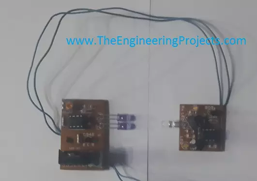
Hello everyone, hope you all are fine and having fun with your lives. Today's tutorial is quite simple and we will have a look at circuit diagram of IR sensor using 555 Timer. There are different types of IR sensors available in the market. IR is abbreviation of infrared and so they use infrared ray for detection of objects. There are many types of IR sensors with different functionality, but in all of them infrared rays are omitted from transmitter and are received by the receiver. and using these ray we can say whether an object is placed in the path or not.

Today we are gonna see how to design your own IR sensor using 555 Timer. We can also interface these IR sensors quite easily with any microcontroller like PIC Microcontroller , Arduino etc. I was also thinking of designing it in Proteus but Proteus doesn't have the IR leds in it so I couldn't do it. IR sensors available in market are quite costly ranging from 10$ to 100$ obviously they are also excellent in efficiency but in engineering cost efficiency also plays an important role so today we are gonna have a look at circuit diagram of IR sensor using 555 timer which will cost you just $2. Before going into the details, lets first have a look at types of IR sensors.

Types of IR sensors

  • There are normally two types of IR sensors available in market.
First Type of IR Sensors:
  • First type is transceiver IR sensor which has both transmitter and receiver in it. This type of IR sensor is used to detect the distance of object from the sensor.
  • In this type of IR sensors, rays are omitted from the transmitter and are reflected back after hitting some object and are captured by the receiver.
  • On the basis of the time taken by these rays to reflected back, we calculate the distance of the object from the sensor.
Second Type of IR Sensors:
  • In these types of IR sensors, transmitter and receiver are not on same chip but on seperate pieces.
  • These types of IR sensors are used for detection of object.
  • For example we need to count people entering in some room then we will place this IR sensor on the door of that room with transmitter on one end and receiver on the other.
  • So, now when some one will enter through the door , he will cut the IR beam and thus the IR light wont be received by the receiver and thus the sensor will know that someone entered.
  • These types of IR sensors are also used in electronic devices like TV remote etc.
In this tutorial we are gonna design this second type of IR sensor using 555 timer. so, lets get started.

Circuit Diagram of IR Sensor using 555 Timer

  • So, here we are gonna design the second type of IR sensor using 555 timer.
  • In this sensor we need to design both the transmitter and the receiver.
  • So, lets get started the transmitter.
  • Design the below circuit on some circuit board:
  • In the above circuit diagram of IR sensor, I have clearly mentioned all the values of components so that you can easily design it. Moreover there are two leds used in it, these are not simple leds. There are IR leds which emits IR rays. the range of this sensor will depend roughly on the number of leds you are gonna use here, as I used two leds.
  • So, now lets have a look at circuit diagram of receiver side.
  • On this side we have use IR led but that one is receiving and will received that IR rays coming from the transmitter IR leds.
  • These are quite simple in designing and you can design it without any trouble. Before going into PCB, its better if you first design them on some wero board or bread board.
  • Here's a manufactured piece of the above given circuit diagrams. The one with two leds is the transmitter and the other one is receiver.
 
  • The image is a bit blur, coz I was in a bit of hurry but they work perfectly fine. :)
  • That's all for today, will see you guys in the next tutorial. Till then take care!!!

What is 555 Timer?

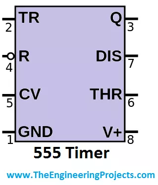
Hello friends, i hope you all are fine and enjoying. Today i am going to share a new tutorial in which I am gonna explain What is 555 timer? We all know about 555 timer, which is an 8-pin IC (integrated circuit), most commonly used in electronic projects, built now a days. As you can see fron its name that it is a timer and designed to generate PWM.

In today's tutorial i am going to explain, what's hidden inside this 555 timer IC and what is 555 timer. A 555 timer is a much compatible electronic device and the biggest feature of this IC is that it able to work on both analogue and digital techniques. Now if we simply consider the output of the 555 timer then, at any particular time, this timer has only 1 definite state. Which means at any time, it will be either ON or OFF. It is not possible that its output is ON and OFF simultaneously. A new invention of 555 timer has also been discovered which is named as 556 timer. 556 is in fact a Dual version of 555 timer and it contains 2 555 timers in a single IC. 556 is a 14 pin IC. Now you will think that 555 timer is a pin IC and as i said that 556 contains two 555 timers then, it should have 16 pins. The answer to this question is that, when two 555 timers are connected to each other then the VCC and GND of both ICs is made common so, we have 14 pins instead of 16. Now let's move towards the basic theme of our tutorial. In this tutorial i will be explain the steps, the pin configuration of 555 timer, It's different modes and project applications.

Internal Design of 555 Timer

Before going into details of what is 555 timer, let's first come to the internal design of a 555 timer. The outer shape of the 555 timer may look like very simple but there is a complex mechanism hidden inside that small IC. A 555 timer contains 25 transistors, 15 resistors and 2 diodes, which are connected to each other in a very complex manner. An interesting thing to know here is that all these components are embedded on a single small silicon chip. Some other series of 555 timers are also available in market like NE555 timer, which we commonly use in our engineering or electronic projects. And the second series is SE555.  SE555 series was designed for military purposes. These operating temperature ranges of both NE555 ans SE555 are given below as:

  • NE555 is mostly used for basic level projects and such high level accuracy is not demanded in it so it is capable to operate from 0 ~ 70 degree Celsius.
  • SE555 was designed for military applications and it is used in those projects where high precision is required. The operating temperature of this IC is -55 ~ +125 degree Celsius.

Pin configuration of 555 Timer

Let's have a look at pin configuration to know what is 555 timer. As I described earlier that 555 timer has total 8 pins. As i described that 555 timer is a multipurpose IC and it is capable to perform variable function. So through some proper arrangement of connections, we can made this IC to do different tasks. Now i will explain the every pin no. and its purpose so that we know the answer to our main question what is 555 Timer ??? :)

  1. The pin designated as pin#1 is GND pin. This pin is used to provide reference voltage or ground to 555 timer.
  2. The pin designated as pin#2 is TR pin. It is used for triggering of 555 timer. The operating voltages of 555 timer is 4.5V ~ 15V. When the operating voltages exceeds 5V then, the 555 timer triggers and it generated output or we can say that now it has crossed that limit above which it will generate output.
  3. The pin designated as pin#3 is the output pin of 555 timer. Through this pin, the output of 555 timer goes to the external circuit. The output depends on the purpose for which you are using 555 timer. For example if you are using your 555 timer to generate PWM then its output will vary. Sometimes it will go High and some time it will go Low.
  4. The pin designated as pin#4 is Reset pin of 555 timer. If you look closely on the first feature image of the tutorial then, you yourself will understand that it is a NOT function. Which means that in order to reset the 555 timer you will have to give '0' at that pin and after the compliment it will become High and 555 timer will 'Reset' .
  5. The pin#5 of 555 is 'CTRL' pin. It is in fact a control pin of 555 timer. This pin gives us the direct access to the internal voltage divider of the 555 timer, which is fabricated inside that small silicon chip. We can divide the voltages according to our output requirements.
  6. The pin#6 is named as 'THR' pin of the 555 timer. For the supply voltages, 555 timer has kept a reference value for them. For example when the supply voltages exceeds 5 volts then, the this pin becomes activated and the 555 timer starts to generate output or it sends data to its output pins.
  7. Pin#7 is named as 'DIS' of the 555 timer. This pin is in fact the discharge pin of 555 timer and used to discharge the capacitors between intervals. This pin has the biggest advantage when, we are generating PWM through 555 timer.
  8. The last pin is pin#8 and it is designated as 'VCC' . This is the supply pin of 555 timer. Source is connected at this pin and as i have already explained that the supply voltages range for 555 timer is 4.5V ~ 15V, but generally it triggers above 5 volts.

Modes of Operation - What is 555 Timer ???

In order to know what is 555 Timer, we should have a look at its modes of operation. 555 timer has 3 major modes of operations. All these modes have there own applications and advantages. All the 3 modes are explained in below:

Astable Mode of 555 timer:

From the name of this mode 'astable mode', you can understand that, in this mode, we don't have any stable output of 555 timer. While operating in this mode, the output will be continuously fluctuating and we will be obtaining a square wave form on the output pin of the 555 timer. To operate the 555 timer in Astable mode, you will have to draw the following circuit, which is shown in the image below:

  • Astable mode is also used to flash lamps and leds. A very similar project named as Sequential LED blinking using 555 timer has also been uploaded by our team. In that project 555 timer was again being used in astable mode.

Monostable Mode of 555 timer:

In this mode of operation the 555 timer gives only one output pulse in addition to the intentional trigger input. For example if you will press the button then, 555 timer will produce a output pulse and its length remains constant until you again press the button and the 555 timer will generate another pulse. The circuit to use 555 timer in monostable mode is shown in the image given below:

  • Monostable mode of 555 timer has wast application. In this state it is used as a timer, touch switches.
  • The biggest example of this mode is to generate PWM. If you recall one of my previous tutorial which was Angle control of servo motor using 555 timer, then at that stage we were using a 555 timer to generate a PWM and through this PWM, we were controlling the angle of micro servo motor.
  • This mode is also used for capacitive measurement and also for missing pulse detection.

Bistable Mode of 555 timer:

The third and the last mode of operation of 555 timer is to use it in bistable mode. This thing is understood from its name 'Bistable' which means this circuit will have 2 stable states, which we are going to control. The circuit diagram to operate a 555 timer in bistable state is shown in the image given below:

  • The above shown circuit is of bistable mode of 555 timer.
  • As you can see in the above figure, we have 2 push buttons. One is connected to 'THR' pin and the other is connected to 'TRIG' pin of 555 timer.
  • When we will press the 'TRIG' button, which means that we have connected the trigger state to ground and its state has become LOW. By doing that the output of 555 timer will become High.
  • On the other hand, when i will press the 'RESET' button then 'THR' pin of 555 timer will be grounded and the output of 555 timer will become LOW.
  • In this way we have made the 555 timer to work in 2 different states and that's why it is called Bistable mode of operation of 555 timer.
If you wanna read more about 555 Timer then you must check below simulations on 555 Timer: Alright friends, that was all from today's post. I hope you have learned something new today and have got your answer for our first question what is 555 timer and if you have any questions then please ask in comments and i will try my best to resolve the issue. Till next tutorial Take Care !!! :)

Traffic Signal Control using 555 Timer in Proteus ISIS

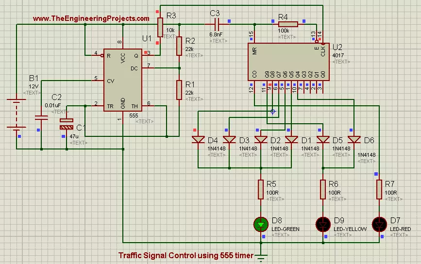
Hello Friends, i hope you all are fine and enjoying. Now i am going to share my new project tutorial which is Traffic Signal Control using 555 Timer. Up till now i have uploaded a no. of projects using 555 timer and i have got much appreciation from my friends, for some 555 timer based projects like How to use Capacitive Touch Sensor in Proteus ISIS, Sequential LED Blinking using 555 Timer and many more.

Now i am going to share another application of 555 Timer and here we will be using a shift register (4017) next to 555 timer to implement Traffic Signal Control circuit. 4017 is a SERIAL IN PARALLEL OUT shift register. Data enters in a serial manner into register and it leaves the register in parallel manner. 4017 is a 10-bit shift register and it needs a clock pulse to shift data from serial input pin to parallel output pins. Now we need a device which can provide continuous clock pulse to Shift Register. Clock pulse is generated either from Micro-controllers or some sort of timers. Here we will be using 555 Timer to generate clock pulse. It is a very easy project to understand and also very simple to implement. These type of projects are generally designed by the Engineering students in their First or Second semester. Now i am done with the theory of the circuit and now lets move towards the designing of the project.

You can also download the complete simulation of the above described project by simply clicking on the button given below:

Traffic Signal Control using 555 Timer in Proteus ISIS

  • First of all place all the components in your proteus workspace,as shown in the image below:
  • Threshold voltage for 555 Timer is 5 volts, and when voltages exceeds this level, 555 timer triggers and it generates a output pulse at its output pin which is ‘Q’ pin.
  • In this project, we will be using a battery of 12 volts as supply voltages.Positive pin (+) of source is connected to Vcc pin of 555 Timer and the Negative pin (-) is connected to GND pin of 555 timer.
  • Pin#3 of 555 timer is connected to CLK pin of shift register and this pin is the data input pin of shift register. Through this pin, 555 timer send data to shift register.
  • At output pins of shift register we have connected 3 Leds, RED, YELLOW and GREEN. Same colors which are used in Traffic Signals.
  • RED led is connected to output pin#12.  YELLOW LED has 2 parallel inputs that are pined at pin#10 and pin#11 respectively. Diodes are connected the way of inputs to block reverse currents. YELLOW led will glow if any of the input will be HIGH.
  • GREEN led has 4 parallel inputs connected at pin# 1,5,6,9 respectively. GREEN led has to blink for longer time, that's why we have connected multiple inputs to it. GREEN led will keep on glowing as along as any of the input will be HIGH.
  • If you connected all the components in their exact position and all the connections are OK, then the final circuit will look like as shown in the image below:
  • Now if you look the above circuit closely then, you will observe that we have connected high valued capacitor (47uf) in the way of trigger pin of 555 timer.
  • The purpose of capacitor is to produce lag in the clock generated by 555 Timer.
  • Now when you will play the simulation then LED will start to glow in periodic manner. First RED led will blink, then YELLOW led will glow and in the end GREEN led will start to glow.
  • All these stages are shown in the image given below:
  • As you can see that state#1 represents the "STOP" state, which means that traffic has to stop.
  • State#2 represents "GET READY" state and it means get ready to GO but you are not allowed to go yet.
  • State#3 represents "GO" state, in which traffic is allowed to Go.

Alright friends that was all for today's project. It was a very simple tutorial and most of its portion have been explained in previous tutorials. So i haven't explain it in much detail. But still if you have any problem then, don't feel shy to ask in the comments. Till next tutorial Take Care !!! :)

Relay Control Using 555 Timer in Proteus ISIS

Hello friends, I hope you all are fine and enjoying yourself. Today I am going to share my new project tutorial which is Relay Control Using 555 Timer in Proteus ISIS. We all know about relays that are used for automatic switching and are magnetically connected while electrically insulated. If you don't know much about relays then I think you should first read What is a Relay? in which I have given a detailed overview of relays and where are relays used? After reading this post you will have a good grip over relay and today's post will be piece of cake for you. Relays are mostly used with some microcontrollers like Arduino or PIC Microcontroller. You might also wanna have a look at traffic Signal Control using 555 Timer, which is good if you are interested in learning 555 Timer.

Now in today's project, it can be understood from its name (Relay Control Using 555 Timer in Proteus ISIS), that we are going to operate and control a Relay through 555 Timer. First of all, if we define the relay, then we can say that 'Relay is an Electrical switch which operates Mechanically'. You should also check this Relay Simulation in Proteus to know how it works. Although some relays operate automatically but since we are working on a very basic project and we will be controlling the relay from an external mean and for this, we will use a mechanical switch. The mechanical switch is in fact a button and we can turn it ON or OFF according to our own choice. It is a very simple and easy project and most of its contents have been described in the earlier tutorials. So, I am not going into much detail and without wasting any time, let's move towards the Hardware of the circuit. But it's my personal advice, try to do design this relay control using the 555 timer project yourself and get to know the practical applications of the 555 Timer in person. You can also download the complete simulation of above described tutorial by simply clicking on the button given below:

Download Project Files

Where To Buy?
No.ComponentsDistributorLink To Buy
1555 TimerAmazonBuy Now
2LEDsAmazonBuy Now
3ResistorAmazonBuy Now

Relay Control Using 555 Timer in Proteus ISIS

  • First of all place all the components in your Proteus workspace as shown in the image given below:
  • Now connect supply voltage (+5 volts)  to Vcc pin of 555 Timer.
  • At the output pin of 555 Timer, which is pin # 3, we will connect our load. By load we mean a 5 volts relay and a simple DC motor is connected next to the relay.
  • As I told you earlier that we are using a manual relay, so a simple push Button is also connected between pin # 3 and relay.
  • If you have connected all the electronic components in their exact place, then the final simulation will look like as shown in the image given below:
  • If you notice the image closely, then you will observe that a Diode is also connected in parallel with the relay coil.
  • A Relay contains a coil. When the voltage source is applied across one end of the Relay and the other end is connected to the ground, then the relay gets energized. And when we remove the source voltages then, it still remains energized and the stored charge tends to flow the reverse current.
  • The reason to connect the Diode is that it blocks the reverse current and only allows the forward current to pass through it.
  • Now run the simulation, if the button is kept in the OFF state then, the voltage will appear across the Relay but it will not operate. To run the load, which is Motor, in this case, we will have to turn the switch ON. This can be seen in the image given below:
  • As you can see in the above image, when the switch was in an ON state, the relay gets no signal and doesn't operate. As we move the switch from ON state to OFF state, the relay gets the signal and it starts to operate the load.
  • Now after reading today's post, you must have a look at Relay Interfacing with Microcontroller which is an advanced tutorial and the benefit of a microcontroller is that now you can control your relay any way you want.
  • Other exciting tutorials on 555 Timer include Seven segment Control using 555 timer and Servo Motor Control using 555 Timer.
  • I have created a small video for this tutorial in which I have shown how to do relay control using 555 Timer, I hope you are gonna like it:
Alright, Friends that was all for today's tutorial about relay control using a 555 timer. I hope, I have conveyed something new today. If you have any questions, then don't hesitate to ask in the comments and I will try my best to resolve them. Follow us through email to get the tutorial straight in your inbox. Till the next tutorial, Take care and Be Safe !!! :)

Seven Segment Display Using 555 Timer in Proteus ISIS

Hello friends, hope you all are fine and enjoying. Yesterday I got a mail from a friend, and he requested me to explain a tutorial about Seven Segment Display. So today, I am going to share my new project tutorial which is Seven Segment Display using 555 Timer in Proteus ISIS. It is a very simple project to understand Modern Digital Electronics.

As you all know, now a days all the Digital Display’s uses Seven Segment Display. So first of all let’s have a little introduction about Seven Segment Display. How they are fabricated and how their LED’s glow in such a beautiful manner? Seven Segment Display (SSD) is the form of electronic device, used to display decimal numbers. Seven Segment Displays are commonly designed in Hexagonal shape but according to our project’s requirement we can also design them in some other shapes like rectangle, triangle, trapezoid etc. Seven Segment Displays may uses LIQUID CRYSTAL DISPLAY (LCD) or LIGHT EMITTING DIODE (LED) for each display segment. In Seven Segment Display all the positive terminals (Anode) or all the negative terminals (Cathode) are brought together to a common pin and such arrangements are known as “Common Anode” or “Common Cathode” arrangement. In this project we will be using Common Cathode arrangement and Hexagonal shape of Seven Segment Display. A simplest form of Seven Segment Display is shown in the image below:

From the above shown image, we can see that we have total 7 LEDs and we will make them glow in such a scheme that the final image will look like a Numerical number. Now if you recall one of our previous project tutorial which was Sequential LED Blinking using 555 Timer, In that project, we are using a 555 Timer in collaboration with a Shift Register. 555 timer continuously provides clock to the Shift Register and Shift Register gives data to its output pins in parallel manner. In today's project, we are also going to use the same concept. We will use a 555 Timer which will continuously provide clock to Shift Register it will enable it's pin accordingly. We can gather this whole information into a single table and also the sequence in which LED's will blink. Such table is called TRUTH TABLE and it is shown in the image given below:

In the above image, '1' means ON state and '0' means OFF state of a particular LED of Seven Segment Display. Above was a little introduction of Seven Segment Display and now, lets move towards Hardware and see How this beautiful display is actually formed.

You can download the complete simulation of above project by simply clicking on the image given below:

Download Seven Segment Display Project Using 555 Timer

Seven Segment Display Using 555 Timer

  • First of all place all the components in your proteus workspace, as shown in the image given below:
  • First of all 555 Timer is installed, after that a Shift Register is added. 555 Timer will give clock to the Shift Register. Since we are using common cathode arrangement. So, the 7 input pin of SSD  are connected to the output pins of Shift Register and the common cathode pin is connected to circuit's main cathode. If you have placed all the components in their exact positions and all the connections are OK. then, the resultant simulation will look like as shown in the image below:
  • Now if you look closely at the upper portion of the image then, you will notice that i have added 2 buttons in the circuit. Left Button in Button # 1 and Right Button is Button # 2.
  • If both the Buttons are kept open and when you will run the simulation then, numerical values will start to come on seven segment display. you can also see it in the below image:
  • Now the switching of button # 1 includes a very interesting feature. First of all play the simulation and Digits will start to run on Seven Segment Display and at any stage when you will press Button # 1 then Seven segment display will vanish but counting will keep on going in the back. And when you will open the Button#1 again then it will show that digit, up-to which counting have reached. Below is a very interesting feature included:
  • During State#1 when Seven Segment Display was showing digit no.2 , we pressed button#1 then, display vanished which can be seen in the state#2. After that when we re-opened the switch#1 then, Seven segment display didn't show the digit no.3 but it shows digit # 8. and this thing can be seen at state#3.
  • Now moving forward, the function of switch # 2 is very simple and easy. During simulation running, when we will press the Button # 2 at any instant then, display will immediately stop at that point. So, we can say that this project can also be used as stop watch and button # 2 controls the stop watch. It can also be seen in the image below:

Seven Segments Displays have a large no of applications. Some of them are listed below:

  1. Digital Clocks.
  2. Electronic Meters.
  3. Basic Calculators.
  4. Electronic Devices to Display Numerical Values. (Generally 14-segments or 16-segments display is used to display full alphanumeric values).

Alright friends, that’s all for today, I hope I have conveyed some knowledge and helped you people in some way. If you have some queries, then ask in comments. Subscribe us via email to get these tutorials straight in your inbox. Till next tutorial, take care and be safe !!! :)

LED Blinking using 555 Timer

Hello friends, hope you all are fine and having fun. Today I am going to share my new tutorial which is Sequential LED Blinking Using 555 Timer in Proteus ISIS. If you recall our one of previous tutorials, which was ‘Multiple LED Flashing Project Using 555 Timer in Proteus ISIS’, but in today’s tutorial we are going to take the same concept to a next level and we are going to make the LEDs blink in either ascending or descending order.

It is a very simple tutorial like the previous one, but the only change is, in this project we have added a Shift Register (4017) next to 555 Timer. 4017 is a Serial IN Parallel OUT Shift Register, which means, at input port it takes data in Serial manner and at output port it will give data in Parallel manner. All types of register needs a clock pulse to operate and this clock is provided by Timers or Micro controllers. In this project we will be using 555 Timer to generate clock pulse. 555 Times gives clock pulse at pin # 3 abbreviated as ‘Q’ pin. And this clock pulse is given at pin # 14 of Shift Register abbreviated as ‘CLK’ pin. Shift Register (4017) has total 15 pins. 2 input pins, 10 output pins. Input data is given at pin # 13, which is called ‘Enable’ pin and register shifts the data sequentially at its output pins. Shift register has 10 output pins which means it is a 10-bit shift register, which means it executes 10-bit data simultaneously. Now dear friends, let’s move towards the hardware of the project but as you know, practice makes a man perfect. Try to do it with your own hand so that, you get to know the practical applications of electrical components in person.

Dear friends, you can also Download the complete simulation of the Sequential LED Blinking Project using 555 Timer, by pressing on the button given below. So, let's get started with Sequential LED Blinking using 555 Timer in Proteus ISIS.

Download Sequential LED Blinking Project Using 555 Timer

Sequential LED Blinking using 555 Timer in Proteus ISIS

  • Weare gonna design a Project named LED Blinking using 555 Timer so let's first have a look at its block diagram.

  • Threshold voltage for 555 Timer is 5 volts, and when voltages exceeds this level, 555 timer triggers and it generates a output pulse at its output pin which is ‘Q’ pin.

  • While designing the circuit, First of all 555 Timer will come, secondly Shift Register (4017) will be connected with it and at the end we will plug LED's. The complete circuit flow diagram is shown in figure below:

  • Now coming towards the designing of the project, first of all, place the components in your Proteus workspace, as shown below in image:
  • Now Output pulse from 555 Timer is connected to input ‘CLK’ pin of Shift Register.
  • Since the register being used is 10-bit, and its outputs are Q0~Q9. The pins Q0~Q5 are connected to LED's D6~D1 respectively.
  • After that Register output pin Q6 is also connected to LED (D2) and it becomes parallel with Q4. Now LED, (D2) has 2 parallel inputs and it becomes HIGH (turns ON) if any of the two Inputs is HIGH.
  • Next we connect the Register output pin Q7 to LED (D3) and then it becomes in parallel with Q3. After doing that LED, (D3) has 2 parallel inputs and it becomes HIGH, if any of the 2 inputs is HIGH.
  • After doing that, now we connect register’s output pin (Q8) to LED (D4) and then it also becomes in parallel with Q2, and LED will start glowing if any of the 2 inputs will be HIGH.
  • Now at the end, we connect Q9 to LED (D5), and then it becomes in parallel with Q1. Now D5 has 2 inputs (Q9 &Q1) and LED will glow if any of the 2 inputs will be HIGH.
  • Now at the end, If you have connected all the components in exact order, and all the connections are OK then, the exact simulation will look like as shown below:
  • Now if we run the Proteus simulation and observe it closely, then we will see that, 555 Timer is continuously generating PWM and the Shift Register set’s its output ports HIGH from Q0~Q9 respectively.
  • First of all Register’s output pin # Q0 becomes HIGH and it send signal to LED (D6) and LED will start glowing. You can also observe this phenomenon in the image given below:
  • Then pin # Q1 becomes HIGH and it send signal to LED (D5) and D5 starts glowing. This can be observed in the figure given below:
  • Then register's output pin Q2 becomes HIGH and sends signal to LED (D4) and D4 starts glowing. This can also be observed in the figure given below:
  • Then Register's output pin Q3 becomes HIGH and send signal to LED (D3) and this LED starts glowing. This stage can be seen in the figure given below:
  • Then Register's pin Q4 becomes HIGH and sends signal to LED (D2) and this LED (D2) starts glowing. This process is shown in the image given below:
  • And in the next step, Register gets its pin # Q5 HIGH and send signal to LED (D1) starts to glow. This process can be seen in this figure:
  • This process keeps on going and when the Register;s next pin becomes HIGH, which is Q6, then it again sends signal to LED (D2) and it starts to glow, and so D3,D4,D5 will glow respectively, and this sequence of LED's blinking will continue, until you stop it manually or by yourself.
  • In the beginning, when LED's Started to blink from Left to Right which was (D6 to D1) , this sequence is called Forward Sequence.
  • After that, LED's started to blink from Right to Left which was (D1 to D6), this sequence is called Reverse or Backward Sequence.
  • We can summarize this whole sequence into a tabular shape, and this table is given in the figure below:
  • This process keeps on going and LED's keeps on glowing in a beautiful sequence. These type of projects are generally used for decoration purposes.

  • So, that's all about Sequential LED Blinking Using 555 timer.

Alright friends, that's all from this post. I hope now you can easily design LED Blinking using 555 timer Project. In the coming tutorials, we will discuss something new regarding 555 Timer applications. Until than, Take Care and Be Safe !!! :)

Syed Zain Nasir

I am Syed Zain Nasir, the founder of <a href=https://www.TheEngineeringProjects.com/>The Engineering Projects</a> (TEP). I am a programmer since 2009 before that I just search things, make small projects and now I am sharing my knowledge through this platform.I also work as a freelancer and did many projects related to programming and electrical circuitry. <a href=https://plus.google.com/+SyedZainNasir/>My Google Profile+</a>

Share
Published by
Syed Zain Nasir