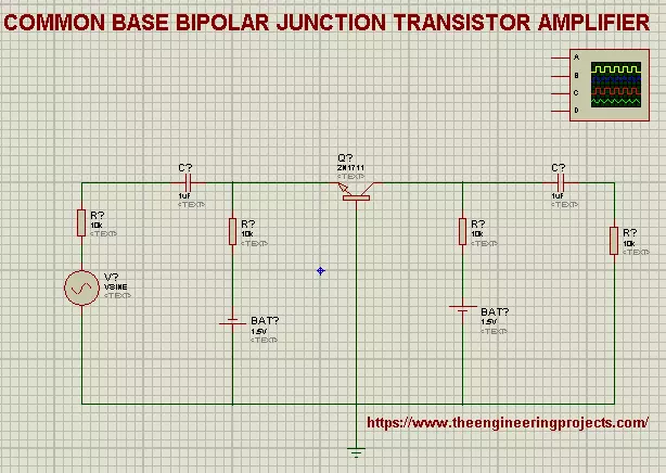
Hi mentees, Welcome to The Engineering Projects. If you are seeking for the Practical Implementation of Common Base bipolar Junction Transistor amplifier then you clicked at the best website because we'll cover the basic concepts and the procedure step by step.
So, Lets start the learning.
What is Common Base BJT Amplifier?
The precise definition of the Common Base BJT Amplifier is:
"The type of Bipolar Junction Transistor Amplifiers in which Base is Common to both emitter and Collector and Current gain is taken from the Base is called Common Base bipolar Junction Transistor Amplifiers."
Recall that a transistor has three regions i.e, Base, Collector and Emitter. Hence we design our Circuit in such a way that we get the output of current from ...
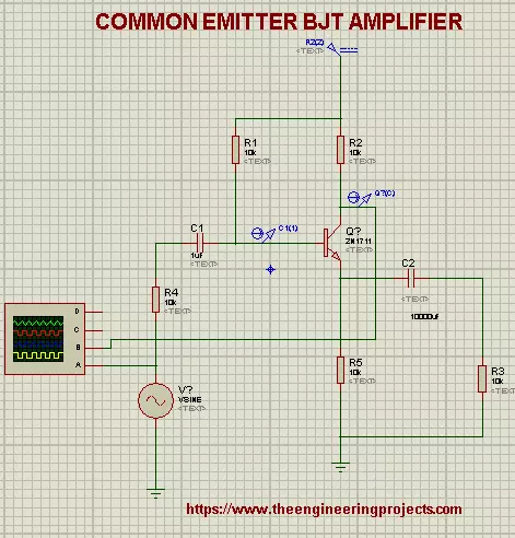
Hi Learners, I hope you are doing good. This lesson is about implementation of one of the types of Amplifiers i.e, Common Emitter BJT Amplifier. But, prior to this, we'll revise some basic concepts so that it will be easy for you to understand the roots of the Experiment.
We'll talk about:
What are Common Emitter Bi-Junction Transistors.
Concepts of Common Emitter Bi-Junction Transistors.
Implementation of Common Emitter BJT Amplifiers in Proteus ISIS.
Why we use Common Emitter BJT in Amplifiers.
What are Common Emitter Bi-Junction Transistors
There are three types of Configurations of a transistor named:
Common Emitter Configuration
Common Base Configuration
Common Collector Configuration
We chose the Common Emitter Configurati ...
Hello Learner! Welcome to another exciting experiment at The Engineering Projects. We hope you are having a great day. In this lecture, we'll seek information about the Boost Converter Circuit from scratch to result in quick and easy steps. So, if you don't know about the experiment then don't worry because every Expert was once a Beginner. We'll talk about the following topics:
What is IRFZ44N MOSFET Boost Converter?
What is the brief introduction of components of circuit?
How can we implement the IRFZ44N MOSFET to design circuit of Boost Converter?
You will know some useful information about the topic in the DID YOU KNOW sections.
IRFZ44N MOSFET Boost Converter
During the experimentation of electronic circuits, we often face the situation ...
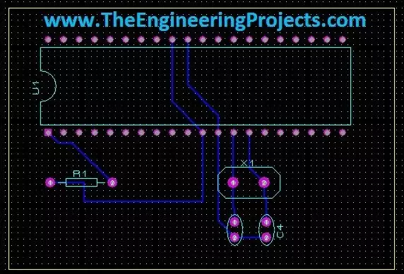
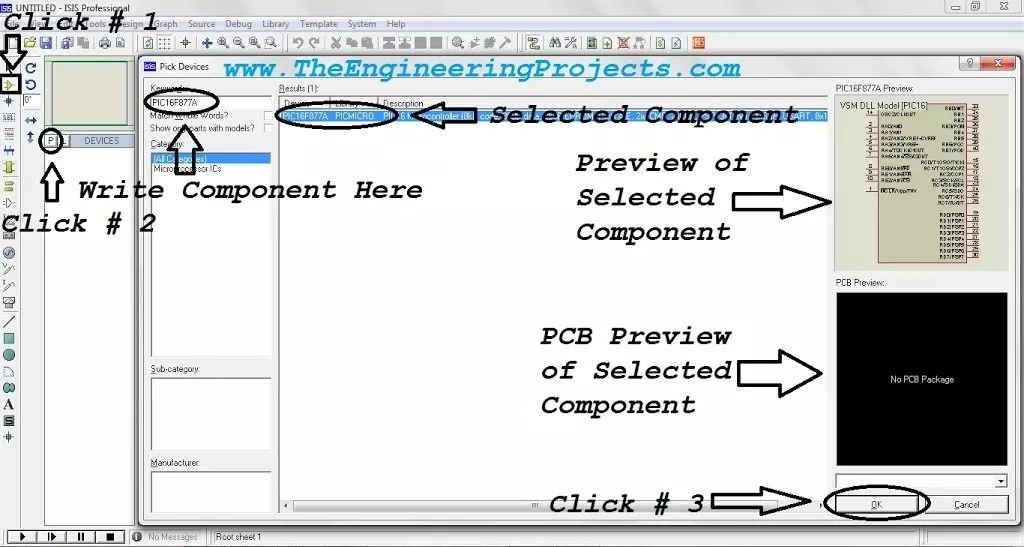
Hello friends, today's the last post of this Proteus tutorial. I have tried my best to explain everything but knowledge is limitless so explore this software, play with it and you will know many new things. Today's topic is about the PCB designing in Proteus. When you install Proteus, you have seen that along with ISIS there's also another package named as Proteus ARES. This Proteus ARES is used for PCB designing. You should also check the Arduino UNO PCB Design for Proteus ARES.
In order to design the PCB in Proteus ARES, first you need to make the circuit of that PCB in Proteus ISIS. You can also make PCB directly but I recommend that use Proteus ISIS first, its quite the easy approach as you don't need to do anything in it and the software in ...
Hello friends, today I am going to post the next lecture of Proteus Tutorial. I am receiving quite a positive response about this Proteus tutorial. In the previous post, we have seen How to use Virtual Terminal in Proteus and today I am going to explain How to use Oscilloscope in Proteus ISIS. This oscilloscope is just the same which you have seen in your electronic or electrical labs. Oscilloscope is basically used to monitor signals or waveforms. Particularly when you are not much aware of the circuit and you need a little debugging then you use oscilloscope.
In oscilloscopes, we can visualize the electrical properties of waveforms, like we can check whats the frequency of electrical signal, what's its voltage or current. Digital oscillosco ...
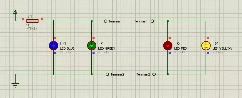
Hello friends, I hope you all are doing great. In today's tutorial, we will simulate our First Electronics Project in Proteus ISIS. It's our 2nd tutorial in Proteus series. In our previous tutorial, we have seen a basic Introduction to Proteus and today, we will design a simple electronics circuit in it and will also simulate it.
If you want to work on Proteus, then you must have some prior knowledge about electronics. Proteus doesn't provide any suggestion about circuit designing so if you don't have electronics knowledge then you can't work with Proteus. Throughout this series, I will keep on explaining electronics circuits as well and will also embedded related components' links. So, if you are new to electronics then no need to worry and just ...
Hello friends, hope you all are fine and having fun with your lives. Today's post is about How to increase Workspace in Proteus. It's our 3rd tutorial in Proteus series. Its quite a simple tutorial and along with this trick, I will also share few commonly used features or Proteus. Once, I was working on a simulation project in which I have to design a complete load management system in Proteus and it was quite messy as I have to include a lot of components and the area of Proteus got quite small for that and then I encountered this problem i.e. where to place the components.
You have seen in Proteus software that there's a blue rectangle which is considered as the workspace in Proteus. This area is constant and doesn't increase or decrease on its ...
Hello readers, I hope you all are doing great. In today's tutorial, I am going to share a detailed Introduction to Proteus. It's our first tutorial in Proteus series. Today's tutorial is for beginners but still I would suggest you to read it once, as I am going to explain why Proteus?
Throughout our Engineering Course, we have to design a lot of electronics or embedded circuits and it's always a best approach to simulate these circuits first on some simulation software i.e. Proteus, PSPice etc., before assembling them on actual hardware. Among these simulation software, Proteus is my favorite one so let's get started with detailed Introduction to Proteus:
Introduction to Proteus ISIS
Proteus Design Sui ...
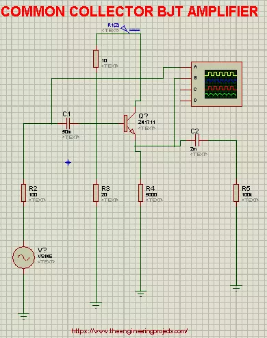
Hi Mentees, Welcome to a new tutorial at The Engineering Projects. Today You will unearth about Common Collector bipolar Junction Transistor Amplifiers. Before this, we learnt about two types of Configurations of Transistors named Common Emitter BJT Amplifiers and Common Base BJT Amplifiers.
In this tutorial We'll discuss about:
Introduction of Common Collector BJT Amplifier.
Basic Concepts for the Common Collector BJT Amplifiers.
Implementation of Common Collector BJT Amplifiers in Proteus ISIS.
Characteristics and advantages of Common Collector BJT Amplifiers.
So that, you can get the best understanding about the topic and its practical implementation.
Introduction
1st of all, We'll have a brief definition of the Common Collector Ampl ...
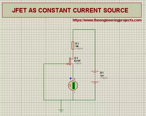
Hi Pupils, Welcome to another Experiment of Proteus at The Engineering Projects. Previously, we saw what are the Junction Field Effect Transistors. Today we'll learn about some of the applications of Junction Field Effect Transistors.
Just before the Experiment, it is useful to revise that:
Transistors are three terminal, unipolar Devices. The terminals of Junction Field Effect Transistor are named as :
Drain
Source
Gate
The Gate Terminal is common to both Source and Drain.
Prior to start, let's clear some Concepts about Junction Field Effect Transistor.
Resistor
Resistor is an electrical device. we define the resistors as:
"A Resister is a two terminal Passive electrical device that shows the electrical resistance and is useful in almos ...