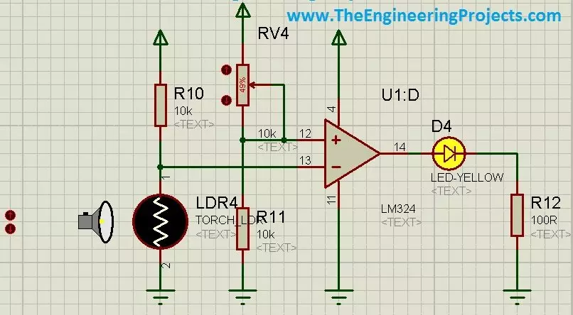
In today's post, I am gonna share how to use LDR sensor in Proteus. Proteus, as we all know, is a very handy software and is used for circuit and PCB designing. It is also used for circuit and programming testing. It is normally used by engineers in their projects and contains a vast list of built-in components. I have posted a lot of tutorials on Proteus and I have got quite a positive feedback from the reader about these tutorials. So, I thought to share another component in Proteus which is quite hidden and I haven't seen much posts on it available online. So, in today's post, first I am gonna explain what is LDR sensor? and we will see where it is used and how it is used. After that I will design a simple circuit in Proteus in which I will turn control a LED using LDR sensor andwill ma ...
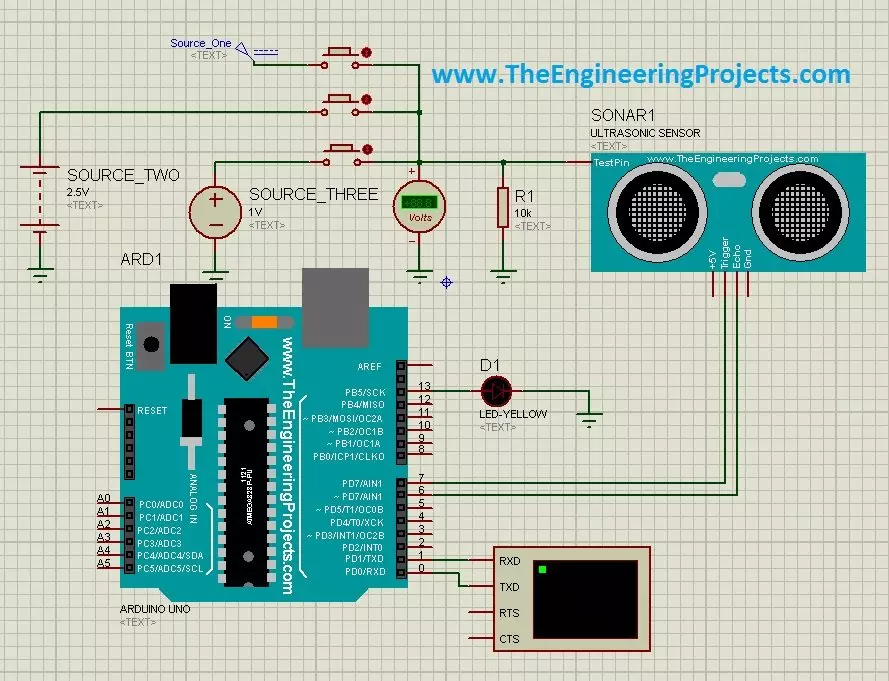
Hello friends, a few days ago I posted an Ultrasonic Sensor Library for Proteus , using which one can easily simulate ultrasonic sensor in Proteus. The post was highly praised by the reader and I have received quite good feedback from the followers. So, I thought of sharing some more examples related to it so that users can get a complete understanding of how to use Ultrasonic sensors in Proteus. Today, we are gonna have a look on different Ultrasonic Sensor Simulation in Proteus. If you haven't read the previous post then first have a look at it because without the installation of Ultrasonic Sensor Library in Proteus, you won't be able to use these examples. Ultrasonic Sensor is used widely in Embedded Systems . Today, I am gonna share three examples of Ultrasonic Sensor Simulation in Pro ...
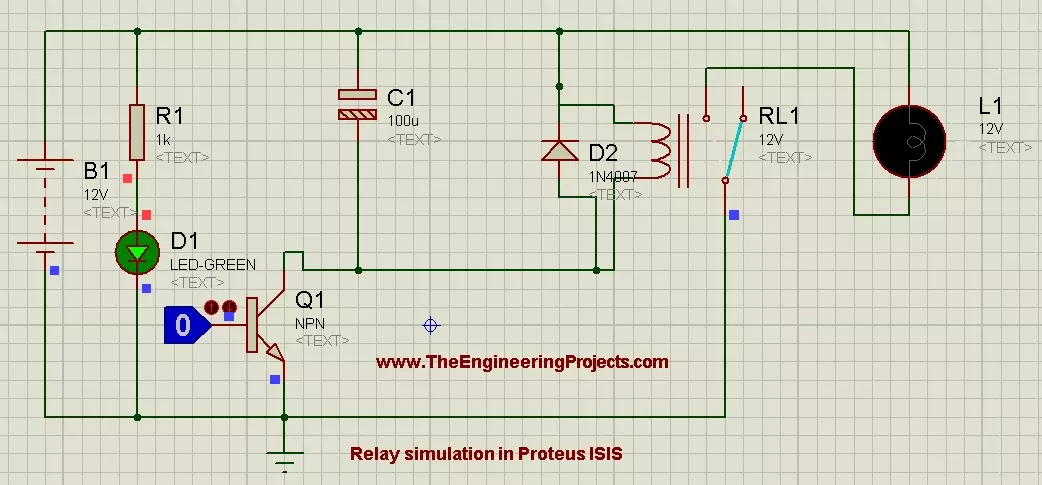
Hello friends! Today, we will learn how to control a relay in Proteus ISIS. We will begin with a simple circuit that energizes a relay coil and switches a lamp, then add a transistor so a low-voltage logic signal can control the coil. This follows naturally from our tutorials on DC motor control , stepper motor control and servo motor control . A relay is useful for switching a load on or off, but it is not the best choice for every motor-control task, particularly rapid speed control. We will keep the demonstration at low DC voltage and use a lamp as the load. The original screenshots remain below, while the connection tables explain the base resistor, protection diode and supply relationships that you should include when building a complete driver circuit. Figure: Relay control demonstra ...
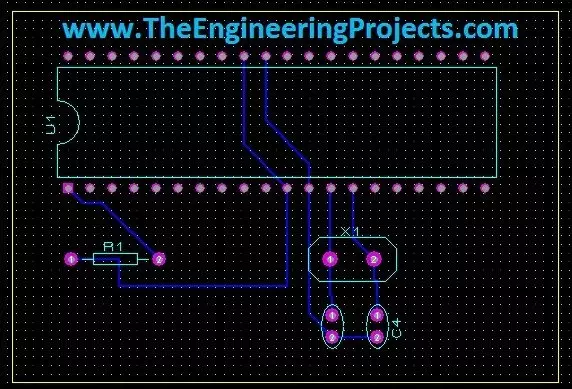
Hello friends! Today we will move from a circuit diagram to a printed circuit board using Proteus ARES. We will use a small PIC16F877A circuit so that placement, connectivity, and routing remain easy to follow. The same sequence of decisions applies when you later design a larger board. Proteus schematic capture describes which component pins belong to each electrical net. PCB layout turns those connections into physical pads and copper tracks. A completed route is useful only when the footprint, pin mapping, power connections, and manufacturing rules are also correct. We will follow the original illustrated workflow: prepare the schematic, transfer its connectivity, define the board edge, place components, and route the board. We will then add the checks needed before sending a design for ...
Hello friends! Today we will design a custom component in Proteus ISIS. This is useful when you need to document a circuit but cannot find the exact module, connector, or device in your installed library. We will draw a simple four-pin symbol, define its connections, and save it so that it can be placed like other library parts. The original purpose of this tutorial is schematic presentation, and we will keep that approach. A clear custom symbol helps another person understand how your project is connected. We will also discuss the extra information required before the same part can be used for PCB layout or electrical simulation. Our example is a fictional device named Test Device with VCC, GND, OUTPUT, and SIGNAL connections. These names let us practise the workflow without claiming to r ...
Hello friends! In the previous tutorial, we controlled the direction of a DC motor in Proteus . Now we will work with a stepper motor, where rotation depends on applying an ordered sequence to the windings. We will begin with the original six-wire simulation, inspect the sequence manually, and then explain how a microcontroller and driver can generate it. The original screenshots use Logic State sources to make individual winding states visible. They are useful for understanding the sequence, but they are not a physical driver circuit. We will preserve the images and add the missing distinction between simulated logic sources, microcontroller outputs, and the winding-current path. By the end, you should understand unipolar and bipolar wiring, wave drive and half stepping, direction reversa ...
Hello friends! In this tutorial, we will design a DC motor control demonstration in Proteus ISIS and then connect its control logic to a PIC16F877A. We will begin by observing how voltage polarity changes the direction of a simulated motor, then explain the driver stage needed between a microcontroller and a physical motor. The original article used Logic State sources and a simplified direct connection to illustrate direction changes. We will preserve those screenshots, but label their purpose clearly. Logic sources and PIC output pins are not substitutes for a motor power driver. The updated practical interface uses an L293D bridge example, with separate logic and motor supplies. We will also correct the relationship between the original schematic and code, add explicit stopping behavior ...
Hello friends! In this tutorial, we will learn how to use the oscilloscope in Proteus ISIS to inspect waveforms, measure voltage and timing, and compare signals at different points in a circuit. In the previous article, we used Virtual Terminal to read serial characters. The oscilloscope lets us examine the electrical waveform behind a signal instead of only its decoded text. We will retain the original inverter demonstration and its screenshots, but begin with the measurement principles needed to interpret them correctly. A waveform that looks smooth is not automatically a verified pure sine wave, and two traces connected to opposite sides of a load do not automatically display the voltage difference across that load. By the end, you should be able to choose a suitable volts-per-division ...
Hello friends! In this tutorial, we will learn how to use Virtual Terminal in Proteus ISIS to inspect serial data and send simple commands to a simulated circuit. It is particularly useful when working with microcontrollers, GSM modules, GPS receivers, and other devices whose behavior can be understood through a serial interface. We will begin with the simplest arrangement: a simulated microcontroller communicating directly with Virtual Terminal. Then we will return to the original article's COMPIM example, which connects a simulation to a real computer serial port. Keeping those two arrangements separate will help you choose the correct components and avoid unnecessary COM-port problems. The aim is to make serial communication visible before building a larger application around it. We wil ...
Hello friends! In this tutorial, we will explore the components and instruments available in Proteus ISIS and learn how to choose the right item for a circuit. Finding a familiar part name is only the beginning. We also need to know whether it has a simulation model, which properties must be configured, and whether the item belongs to the schematic, the measurement setup, or a later PCB design. This article continues our practical Proteus series after designing an LCD circuit with a PIC microcontroller . We will cover ordinary components, displays, motors, serial tools, and shift registers, then connect each topic to the more detailed tutorials already available in the series. My aim is to help you build a sensible test circuit instead of placing unfamiliar parts and hoping that the simula ...