Hello friends, I hope you all are doing great. Today, I am going to share the new ZS-X11H BLDC Driver Library for Proteus Simulation, the 39th library of our motor series. If you have searched for a Proteus simulation of the ZS-X11H, this is the red driver board that people buy for brushless motors with Hall sensors: the e-bike hub motors, the hoverboard wheels, the NEMA 17 BLDC motors of small machines. It takes 6 to 60 V and up to 400 W, reads the motor's three Halls and switches its three phases itself, so a microcontroller only gives it a speed, a direction, a stop and a brake.
ZS-X11H BLDC Driver Library for Proteus Simulation
Latest version: V1.0 (November 2026, this tutorial)
Other motor drivers: L298 · L9110S · TB6612FNG · BTS7960 · A4988 / DRV8825 · 28BYJ-48 + ULN2003 · PCA9685 Servo · Relay Module · 30A Brushless ESC · TB6600 Stepper Driver · 60A Brushed ESC · DRV2605L Haptic Driver · SimpleFOC Mini Driver · AC Dimmer Module · TMC2209 Stepper Driver · DRV8833 Motor Driver · L293D Motor Shield
Motors: SG90 Servo · TT Gear Motor · 28BYJ-48 Stepper · NEMA 17 Stepper · MG996R Servo · N20 Encoder Motor · JGA25-370 Encoder Motor · FS90R 360 Servo · 130 DC Motor · A2212 Brushless · X27.168 Gauge · Analog Panel Meter · DC Tachogenerator · LM393 Speed Sensor · MG90S Servo · DS3218 Servo · L12 Linear Servo · JGB37-520 Motor · RS-775 Motor · JGY-370 Worm Motor · 12V Linear Actuator · Coin Vibration Motor · Mini Submersible Water Pump · 12V Peristaltic Pump · 4-Pin PC Fan · 12V Push-Pull Solenoid · NEMA 23 Stepper Motor · Micro Linear Stepper · TYJ50 Synchronous Motor · Quartz Clock Movement · Air-Core Gauge · Electromechanical Counter · Split-Flap Display · Electric Bell · Wind Turbine · 8520 Coreless Motor · Car Wiper Motor · Car Door Lock Actuator · 12V Solenoid Water Valve · 12V Holding Electromagnet · Mini Air Pump · Planetary Gear Motor · 540 RC Motor · LRA Vibration Motor · 42BLF Hall BLDC Motor · 2204 Gimbal Motor · 120mm 230V AC Fan · NEMA 17 Closed-Loop Stepper · NEMA 17 Linear Stage · Pan-Tilt Bracket · 4-DOF Robot Arm
Helping Tools
- Serial Monitor Advance: a serial terminal window for the UART of your board
- Serial Monitor Expert: the serial monitor with extra debugging tools
- LCD Library for Proteus V3.0: 16x2, 20x4 and I2C LCDs to show your readings
Our library brings the ZS-X11H into your Proteus simulation at its true size, a 63 x 45 mm board with its capacitor, the speed potentiometer and its jumper, the six MOSFETs, the screw terminals and the Hall connector. The simulation model does what the board does: six-step commutation from the Halls, the speed from P as a voltage or a PWM, DIR, STOP and BRAKE, the SC speed pulses, a soft start, a current limit and a locked-rotor cut. The pop-up shows the bridge with its six switches, the current's path and the phase currents. In the demo an Arduino holds our 42BLF motor at a set speed with a PI loop, under a load, in reverse and through a brake.
NOTICE: Our team has put a lot of effort into these small parts: the bodies, the animation and the pop-ups are all our own design, and you get them free. Your feedback is the fuel that keeps us going, so please tell us what you think in the comments below or in the Motor Driver board of our forum. And if our free libraries help you, you can buy us a coffee. So, let's get started with the ZS-X11H BLDC Driver Library for Proteus Simulation:
What is the ZS-X11H?
A brushless DC motor has no commutator, so something must switch its coils in the right order as it turns. The ZS-X11H is a ready-made board for that job. On it sit a controller, a gate driver and six MOSFETs arranged as three half-bridges, one for each of the motor's phases. Each half-bridge can connect its phase to the supply, to ground, or leave it open. The controller reads the motor's three Hall sensors, works out which of the six steps the rotor is in, and switches one phase to the supply, one to ground and leaves the third open. When the rotor moves on by 60 electrical degrees, the Hall code changes and the board moves to the next step.
Speed control is a PWM: the high side switches on and off quickly, so the motor sees the average voltage. On the board the speed comes from three places. The blue potentiometer sets it when the jumper is on. With the jumper off, the P terminal sets it, either from a voltage of 0 to 5 V or from a PWM signal of 2.5 to 5 V at 1 to 20 kHz, whose duty becomes the board's own duty. That makes it easy to drive from an Arduino pin.
| Terminal | What it does |
|---|---|
| V+ / V- | the supply, 6 to 60 V (the board is rated 15 A, 400 W) |
| MA MB MC | the motor's three phases |
| Hall: +5V GND Ha Hb Hc | the motor's Hall sensors and their 5 V supply |
| P / G | the speed input: 0 to 5 V, or a PWM; G is the control ground |
| DIR | low = reverse (open or high = forward) |
| STOP | low = all six switches off, the motor coasts (open or high = run) |
| BRAKE | high = the three low sides on, the windings shorted (open or low = no brake) |
| SC | speed pulses: a toggle at every Hall edge |
| 5V | a 5 V output from the board |
How the Board Commutates the Motor
The six steps follow the Hall code. For the common 120-degree Hall motors the table is the same: the motor's Hall A, B and C go to Ha, Hb and Hc, its phases A, B and C to MA, MB and MC. With DIR high the board uses the table below; with DIR low it switches the same two phases with the current the other way round, so the torque and the motor turn the other way.
| Hall code (Ha Hb Hc) | To the supply (PWM) | To ground | Open |
|---|---|---|---|
| 101 | MA | MB | MC |
| 100 | MA | MC | MB |
| 110 | MB | MC | MA |
| 010 | MB | MA | MC |
| 011 | MC | MA | MB |
| 001 | MC | MB | MA |
SC toggles at every Hall edge, so it makes three pulses for every pair of the motor's poles in one turn. For an eight-pole motor, four pole pairs, that is 12 pulses a turn, so the speed in RPM is 60 times the SC frequency divided by 12, or five times the frequency.
Features of the ZS-X11H BLDC Driver Library for Proteus Simulation
- The board at true scale: the red 63 x 45 mm board with its capacitor, the potentiometer and the jumper, the controller, six MOSFETs, the green terminals and the white Hall connector; the power LED lights at run time.
- Six-step commutation: the standard 120-degree table from Ha, Hb and Hc, every Hall edge at its time; DIR low reverses the table.
- STOP and BRAKE: all six switches off, or the three low sides on to short the windings; open inputs read as the board's pull-ups do.
- The speed input: P as a voltage or as a PWM (its duty from the average against its swing), or the onboard potentiometer with the jumper on; a soft start and stop of 4 per second.
- SC speed pulses: a toggle at every Hall edge, three pulses per pole pair a turn.
- Protections: a cycle-by-cycle current limit at 20 A, a locked-rotor cut after 2 s without a Hall edge, off under 6 V, the bridge cut over 63 V; Hall faults reported.
- A pop-up: the bridge with Q1 to Q6 on, switching or off, the current's path and the phase currents; the speed command and the duty; the controls and the protections; graphs, an event log and a check page.
- A complete package: about 1.2 MB with the library, our Arduino UNO V4.0 and the demo, without the source code of the model.
The ZS-X11H in Proteus
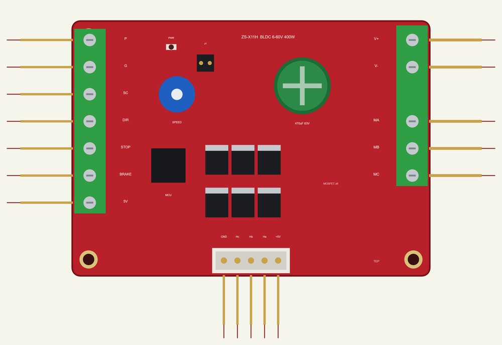
The device is ZSX11HTEP in TEPZSX11H.LIB, under Electromechanical > Motor Drivers, with the prefix U and the mixed model TEPZSX11H.DLL: the bridge, P and the 5 V outputs are analog, the Halls and the controls digital. Search ZSX11H in Pick Devices. The control terminals are on the left, P, G, SC, DIR, STOP, BRAKE and 5V; the power terminals on the right, V+, V-, MA, MB and MC; the Hall connector along the bottom. Three properties: JUMPER (OFF: P sets the speed, ON: the potentiometer), POT (the potentiometer's position in %) and POLES, the motor's poles, used only for the speed the pop-up shows.
Download ZS-X11H BLDC Driver Library for Proteus Simulation
Click the button below to download ZS-X11H-BLDC-Driver-Library-for-Proteus-v1.0.zip (about 1.2 MB, without the source code of the models):
ZS-X11H BLDC Driver Library for Proteus V1.0- README.txt: installation, the demo, the wiring, troubleshooting and the limits of the simulation.
- Proteus Library Files:
TEPZSX11H.LIBandArduinoV4TEP.LIB. - Proteus Model Files:
TEPZSX11H.DLLandTEPARDUINO.DLL. - Arduino Code: the demo sketch.
- Proteus Simulation: the demo project, its HEX file and copies of the DLLs.
No Proteus yet? Read How to Download and Install Proteus 7 and 8. New to libraries? Follow How to Install a New Library in Proteus.
How to Install ZS-X11H BLDC Driver Library for Proteus Simulation
- Close Proteus and extract the whole zip file, for example to your Desktop.
- Copy the files from Proteus Library Files into the LIBRARY folder of Proteus.
- Copy the files from Proteus Model Files into the MODELS folder.
- Delete
TEPZSX11H.IDXfrom the LIBRARY folder if it is there. - The demo's motor is our separate 42BLF Hall BLDC Motor Library for Proteus Simulation: install its LIB and DLL too.
- Start Proteus, press P and search for ZSX11H.
Proteus Simulation of the ZS-X11H with Arduino
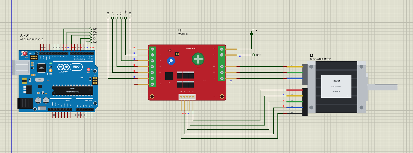
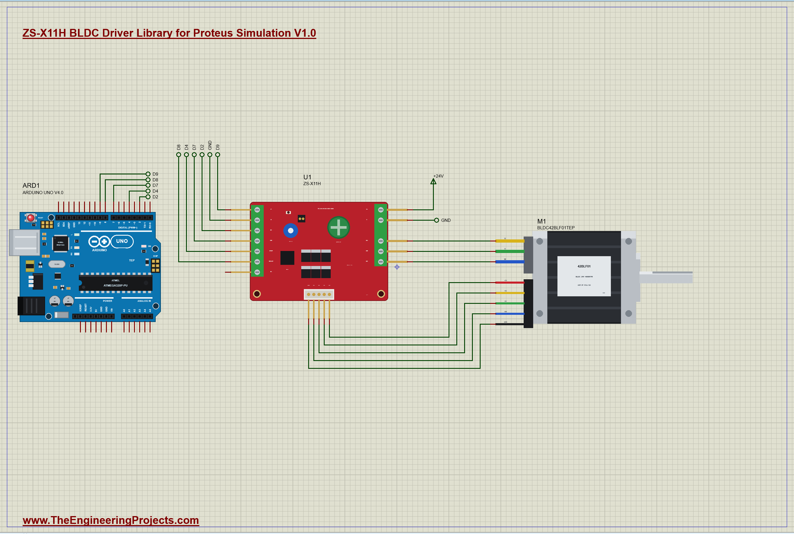
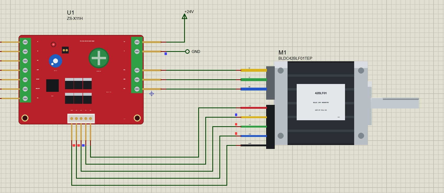
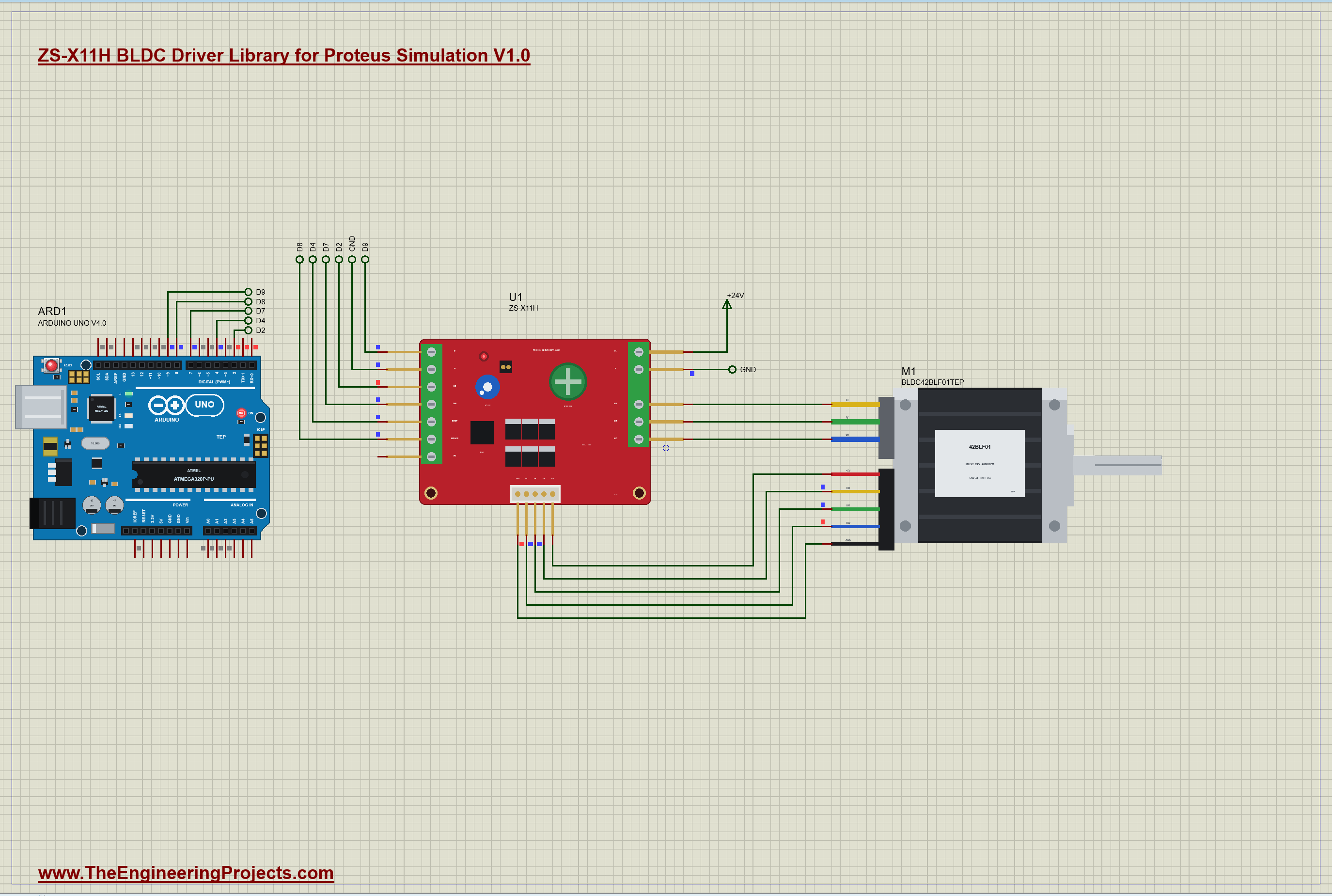
The demo has our Arduino UNO Library for Proteus V4.0 with its built-in monitor, the same window as our TEP Serial Monitor Advance for Proteus. The board U1 sits on a 24 V terminal, and its MA, MB and MC go straight across to M1, the 42BLF01 NEMA 17 motor from our separate 42BLF library (TEPBLDC42.LIB and TEPBLDC42.DLL), so install it first. The motor's Hall cable runs back under the board to the Hall connector. The motor carries a light load of 0.02 N.m and a 300 g.cm2 flywheel. Open ZSX11H-BLDC42-ArduinoUnoV4.pdsprj.
Five wires go to the UNO: D9 drives P with a 3.9 kHz PWM, D7 is DIR, D4 is STOP, D8 is BRAKE, and SC comes back to D2, an interrupt pin. G goes to the UNO's ground. The jumper is off, so P sets the speed.
The Sketch
This time the UNO does not just set a duty; it holds a speed. An interrupt on every rising edge of SC adds up the time between the edges:
void onSc() { unsigned long now = micros(); if (riseUs) { sumUs += now - riseUs; rises++; } riseUs = now; }Every 50 ms the loop turns the mean time between the edges into RPM, with 12 rising edges a turn:
if (n) { rpm = 60e6 / ((float)s / n * SC_PER_TURN); lastRiseSeen = now; }Then a PI controller sets the duty from the error, the target minus the speed, and its integral. The integral only grows while the output is between 0 and 1, so it cannot wind up while the duty is pinned at a limit:
      float e = target - rpm;
      float u = KP * e + integ + KI * e * LOOP_MS / 1000.0;
      if (u > 0 && u < 1) integ += KI * e * LOOP_MS / 1000.0;
      setDuty(u);
The brake is one line: the duty to zero and BRAKE high.
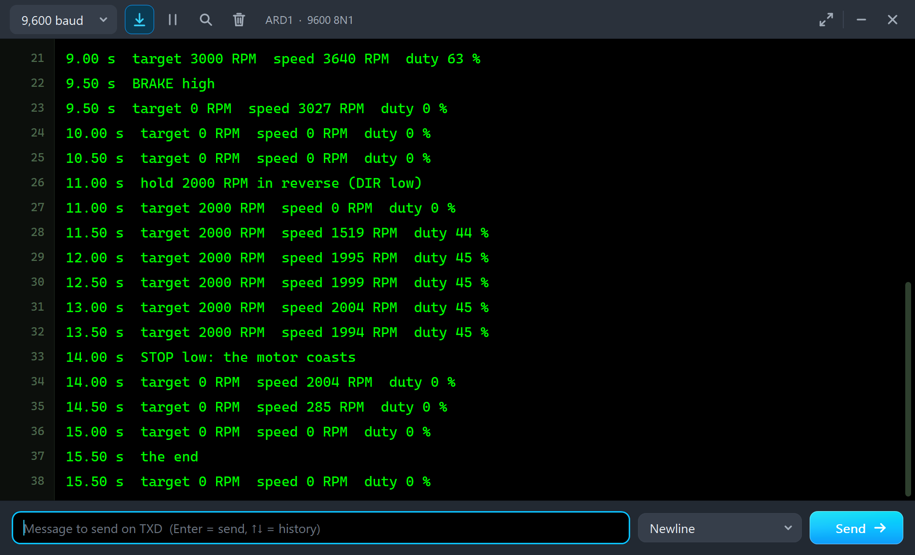
case BRAKING: mode = BRAKED; target = 0; integ = 0; setDuty(0); digitalWrite(BRAKE_PIN, HIGH); break;The program: hold 1500 RPM at 2 s, 3000 RPM at 5 s, BRAKE at 9.5 s, hold 2000 RPM in reverse at 11 s, STOP at 14 s and the end at 15.5 s. Afterwards you can type in the monitor: f 2500 holds 2500 RPM forward, r 1000 1000 RPM in reverse, s stops and b brakes.
ZS-X11H Simulation Results
Open the project and press Run. The program runs 15.5 simulated seconds, which Proteus ran in under four minutes on our PC with both pop-ups open and the pictures being taken. Click the board to open its pop-up. Every number below comes from one simulation run, the demo exactly as it ships, plus two clicks on the motor's load chips.
Holding 1500 RPM
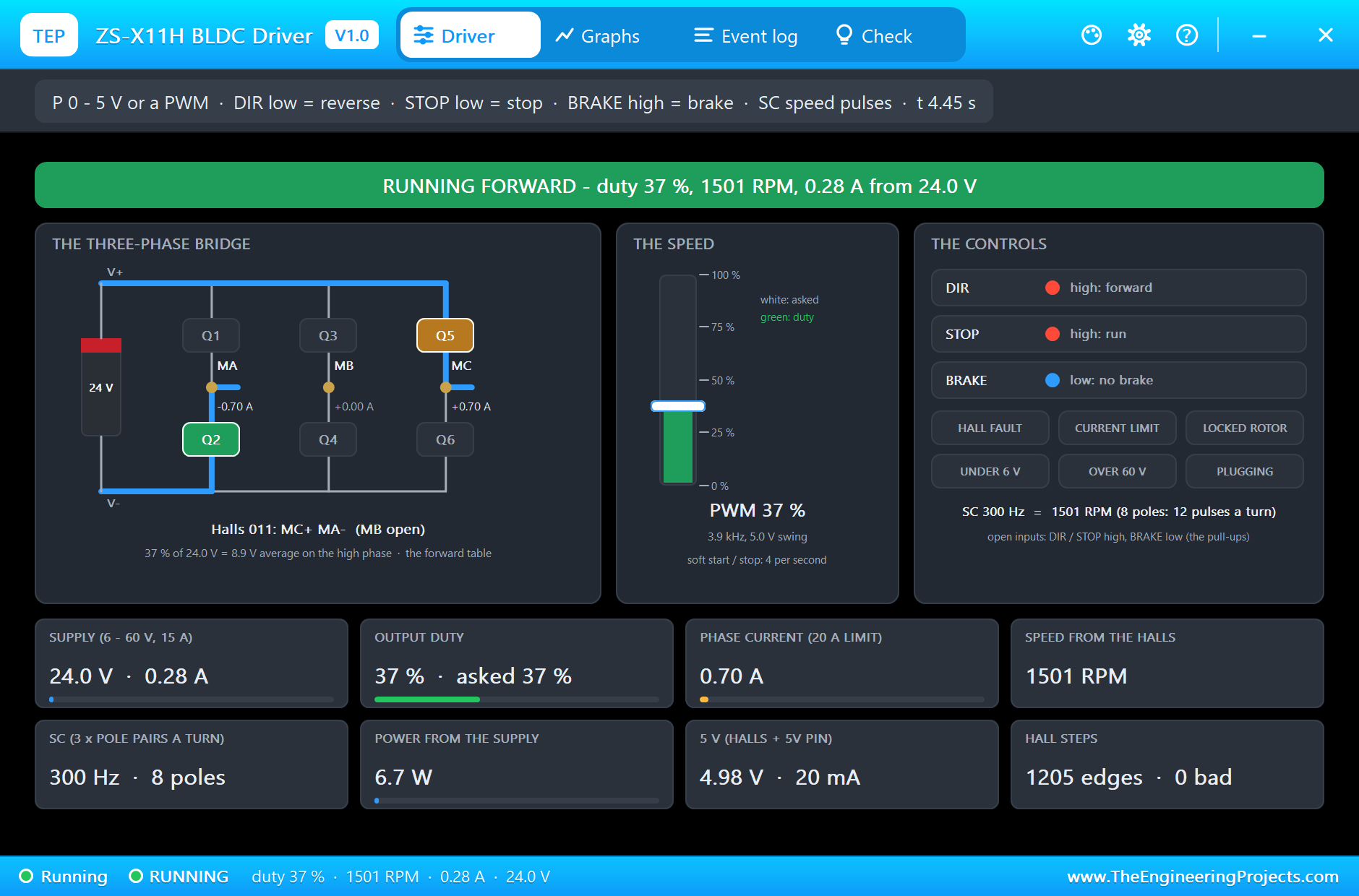
At 2 s the sketch asks for 1500 RPM. The board finds the PWM on P, 3.9 kHz with a 5.0 V swing, and its duty follows with the soft start. In the picture the loop holds 1501 RPM at 37 % duty. The bridge shows the step for the Hall code 011: Q5 switching, so MC is on the PWM, Q2 on, so MA is on ground, and MB open; the current's path is drawn in blue, 0.70 A into MC and out of MA. 37 % of 24 V is 8.9 V on average. The supply gives only 0.28 A, 6.7 W, because it supplies the phase current only while the high side is on. SC runs at 300 Hz, which is 1501 RPM for the eight-pole motor, and the Hall steps all came in order.
The UNO's monitor prints the target, the speed it measures from SC and its duty twice a second.
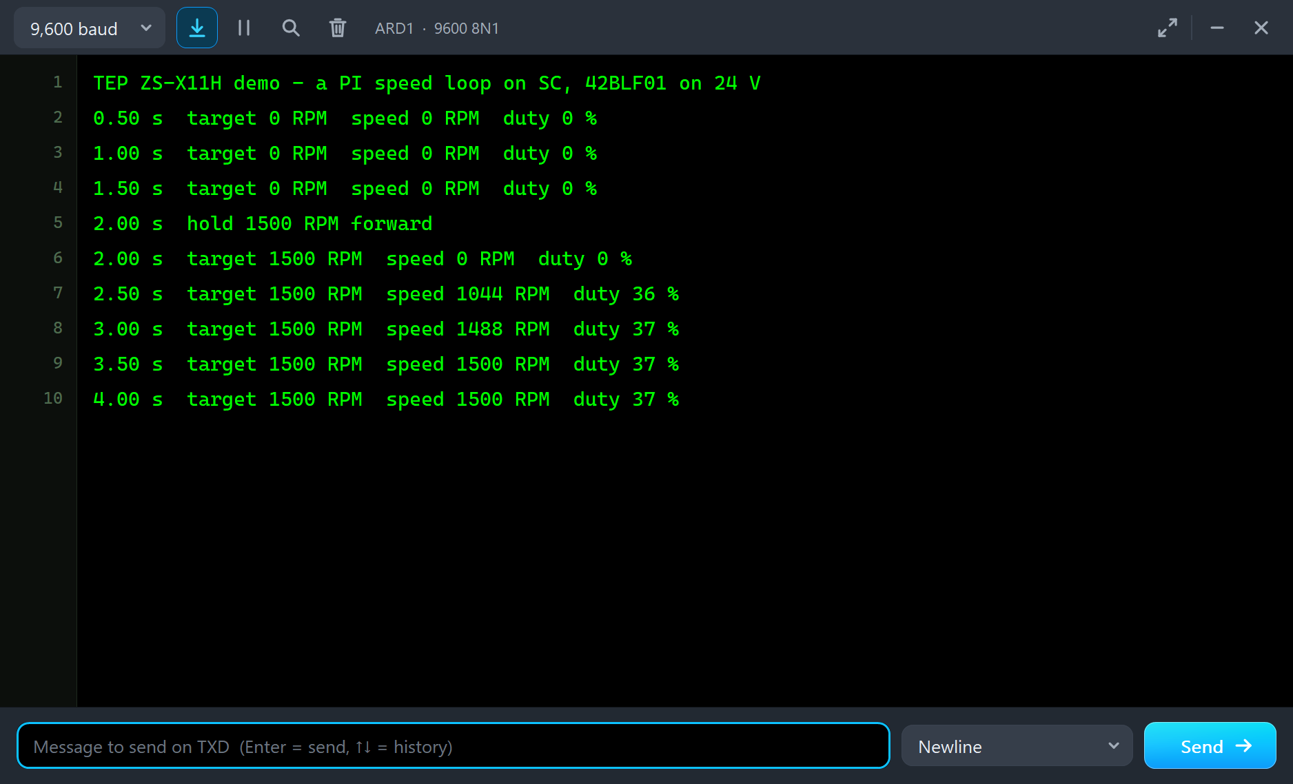
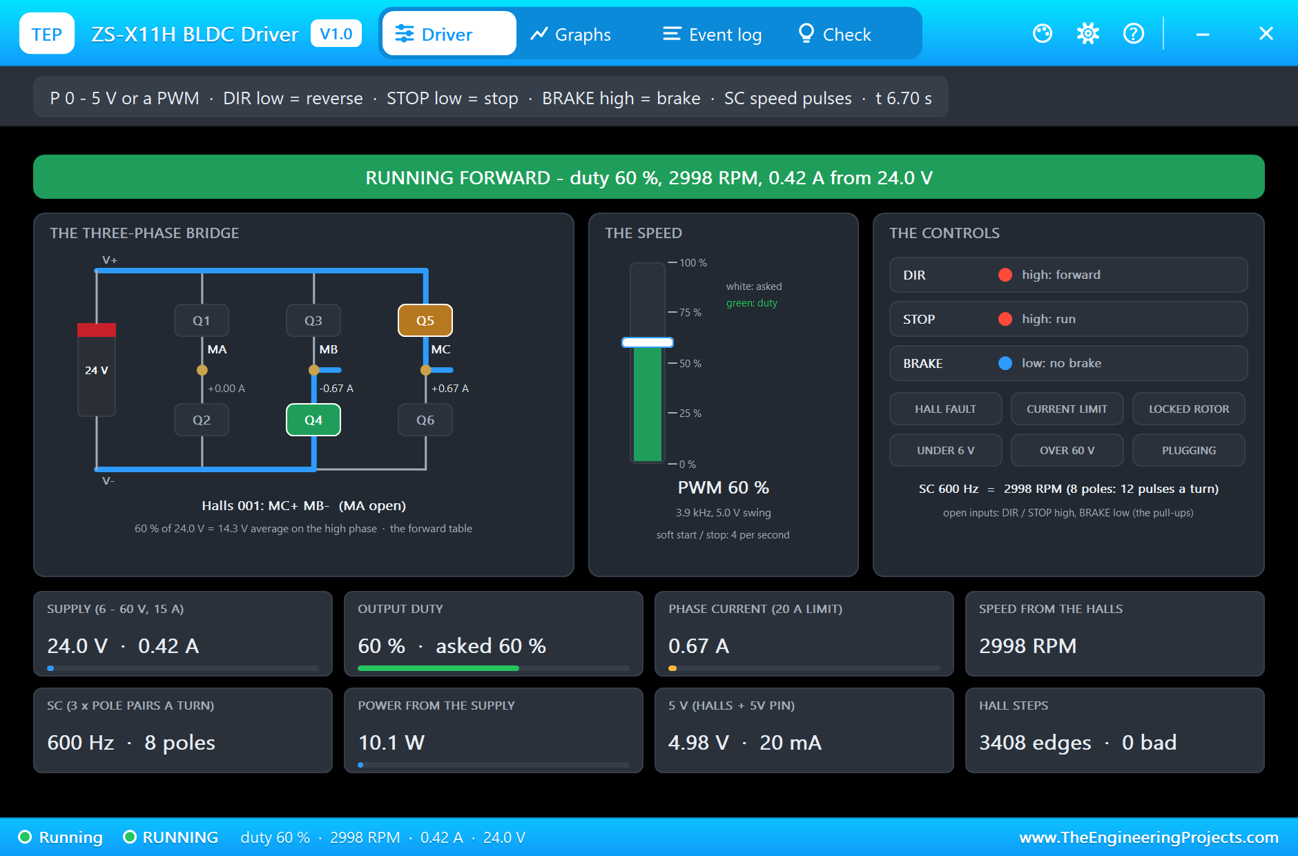
At 5 s the target goes to 3000 RPM, and the loop settles at 2998 RPM with 60 % duty, 0.42 A from the supply and SC at 600 Hz.
The Rated Load
Now the test of a speed loop. At 3000 RPM we clicked the Rated 0.063 chip on the motor's pop-up, which puts the motor's rated torque on the shaft. The motor slows for a moment, the error grows, and the loop raises the duty: the Event log notes speed 84 % from P. In the picture the speed is back at 3004 RPM with 85 % duty, 20.4 V on average. The phases carry 1.92 A, the supply gives 1.65 A, 39.5 W, and SC reads 601 Hz.
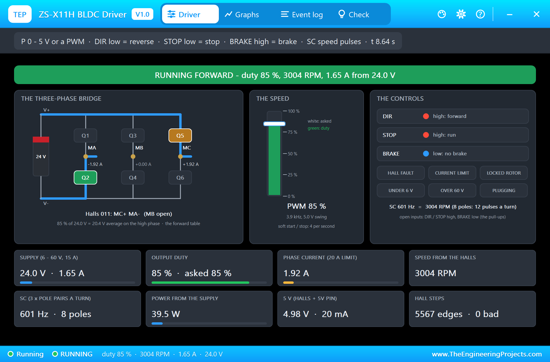
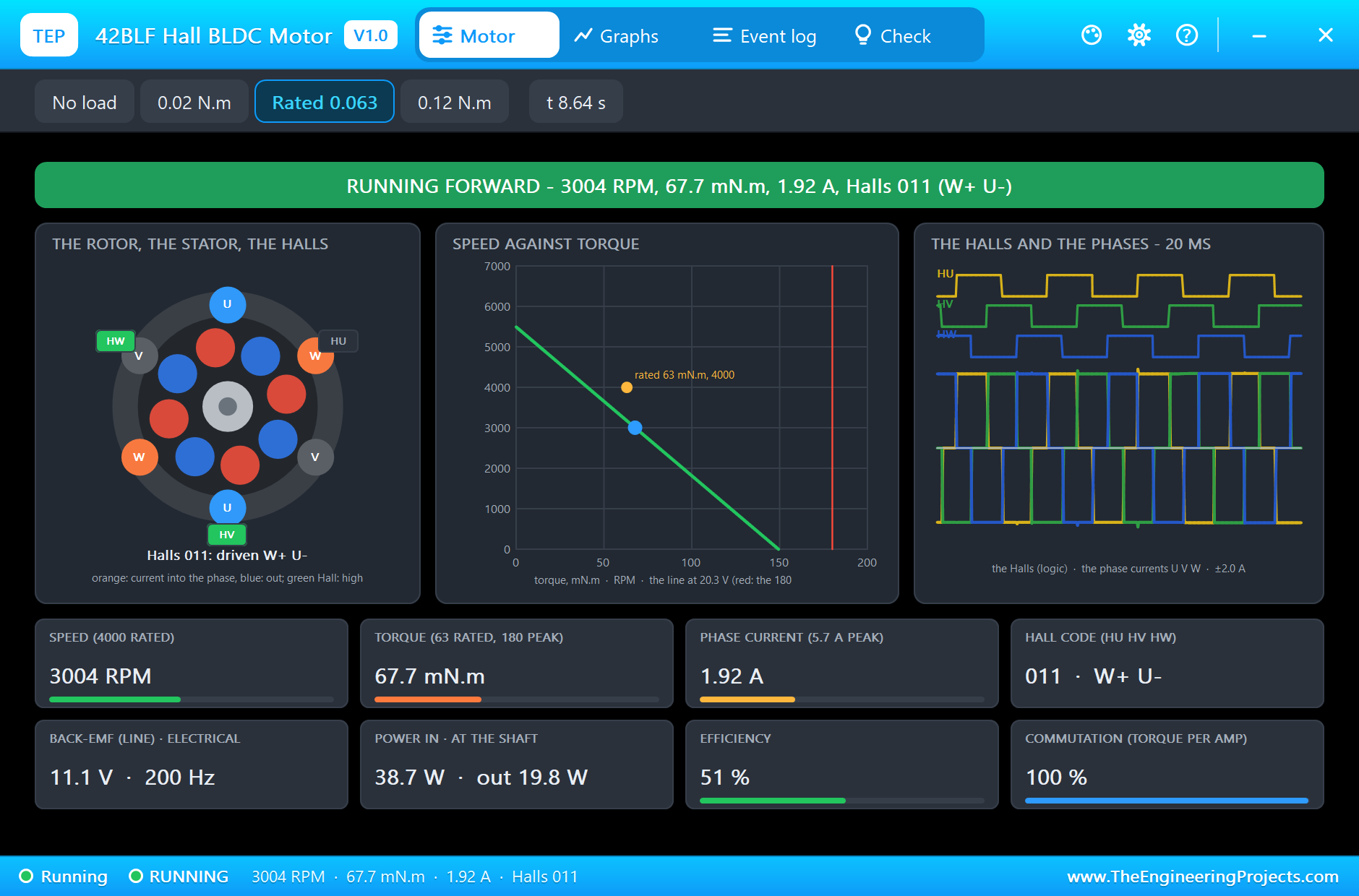
The motor's own pop-up shows the same moment: 3004 RPM, 67.7 mN.m, 1.92 A, 51 % efficient, and the commutation figure at 100 %, so the board energises exactly the pair each Hall code asks for.
Then we clicked the 0.02 N.m chip to take the load off. Now the duty is far too high for the light load, and the motor races ahead before the loop pulls it back: the monitor prints 3640 RPM at 63 % duty at 9 s, and the Event log notes the duty back at 60 %. That overshoot is what a load step does to a PI loop; a faster loop, or one that also watches the current, would keep it smaller.
BRAKE, Reverse and STOP
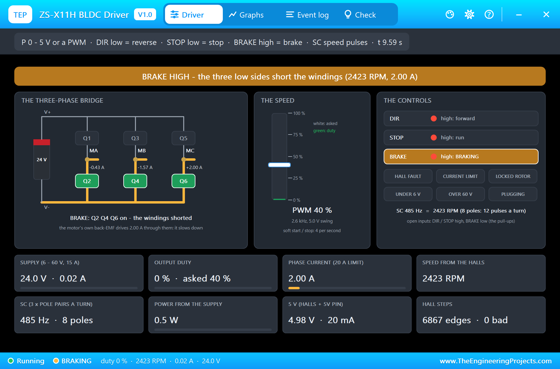
At 9.5 s the sketch sets the duty to zero and BRAKE high. The board turns on Q2, Q4 and Q6, the three low sides, which short the windings together. The motor becomes a generator into a short circuit: its own back-EMF drives the current, drawn in orange, and that current brakes it. The Event log notes BRAKE high at 3017 RPM. In the picture it has slowed to 2423 RPM with 2.00 A in the windings, while the supply gives nothing to the motor. The speed card still shows the last window of the PWM on P, but with BRAKE high the board ignores P.
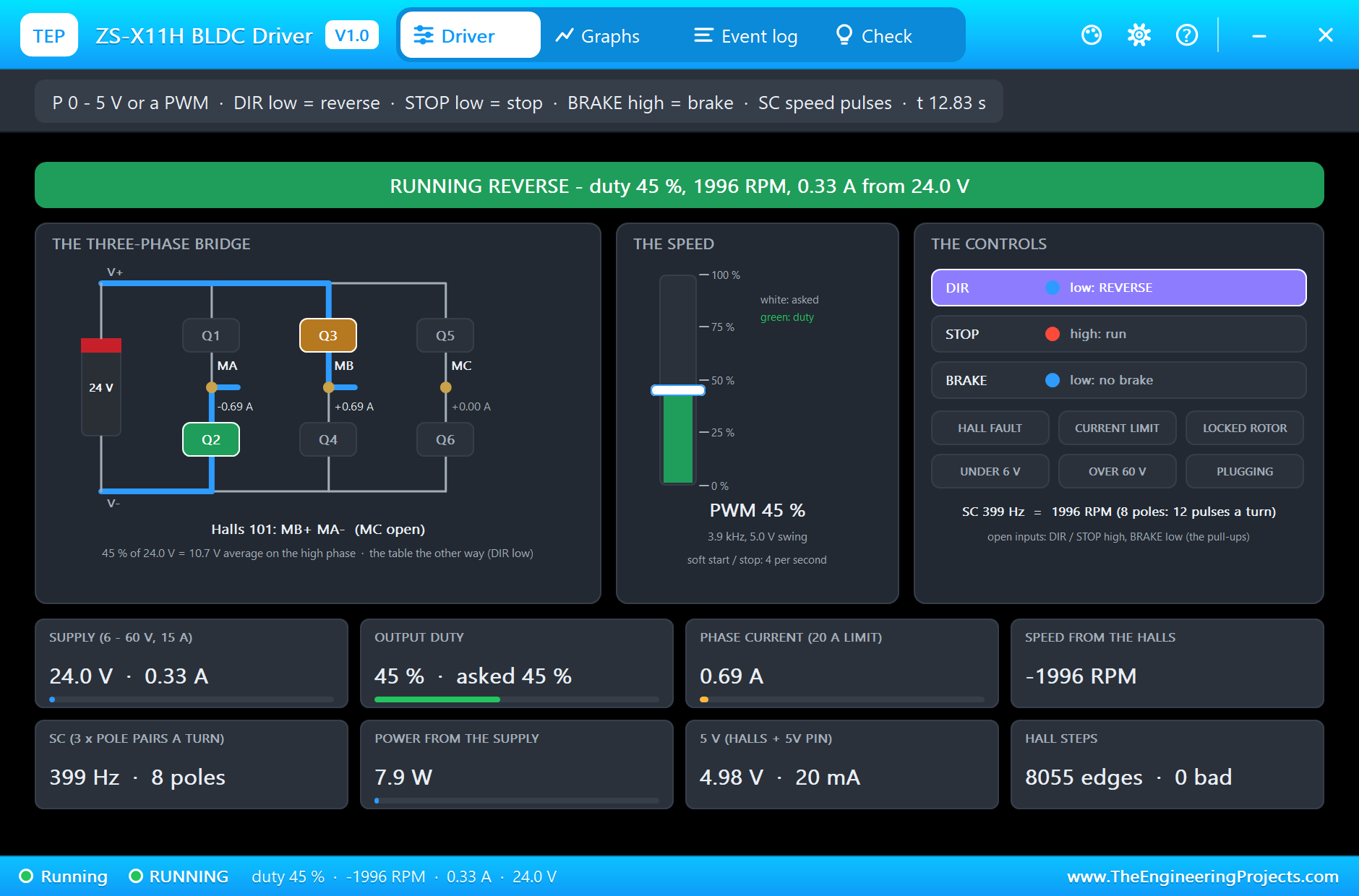
At 11 s the sketch releases the brake, sets DIR low and asks for 2000 RPM. The pop-up marks DIR in purple: REVERSE. For the Hall code 101 the forward table would put MA on the PWM and MB on ground; reversed, MB is on the PWM through Q3 and MA on ground through Q2, and the line under the bridge says the table the other way. The loop holds 1996 RPM, shown as negative, with 45 % duty, 10.7 V on average, 0.69 A in the phases and 0.33 A from the supply; SC reads 399 Hz. The monitor shows the loop steady between 1994 and 2004 RPM.
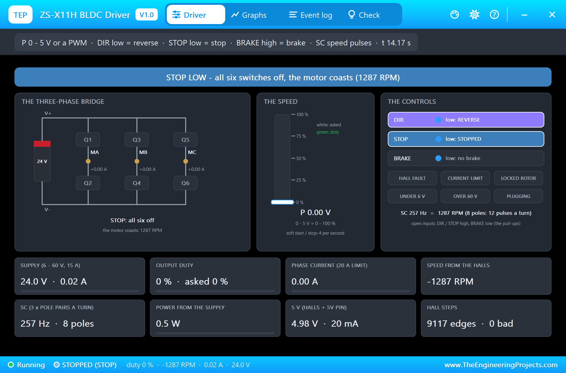
At 14 s the sketch pulls STOP low. All six switches turn off and the motor coasts. In the picture it still turns at 1287 RPM with no current at all, the flywheel slowed only by the load and the friction. The monitor prints 2004 RPM at 14.00 s, 285 RPM at 14.50 s, and then zero.
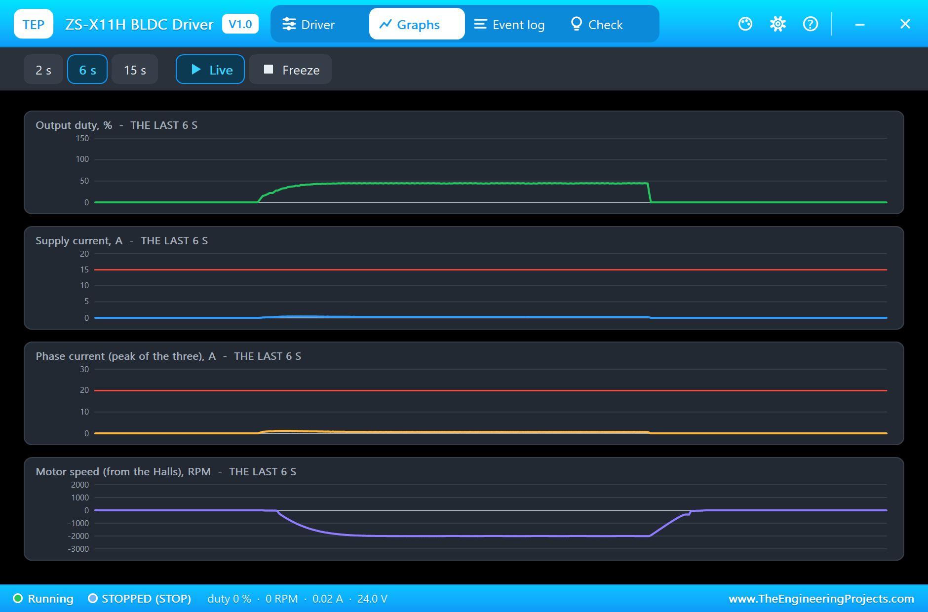
The Graphs, the Event Log and the Check Page
The Graphs page plots the output duty, the supply current, the peak phase current and the speed from the Halls over the last 2, 6 or 15 simulated seconds. The last six seconds show the reverse run: the duty rising with the soft start and the loop, the speed going below zero and settling, then STOP, the duty to zero and the speed coasting back to rest.
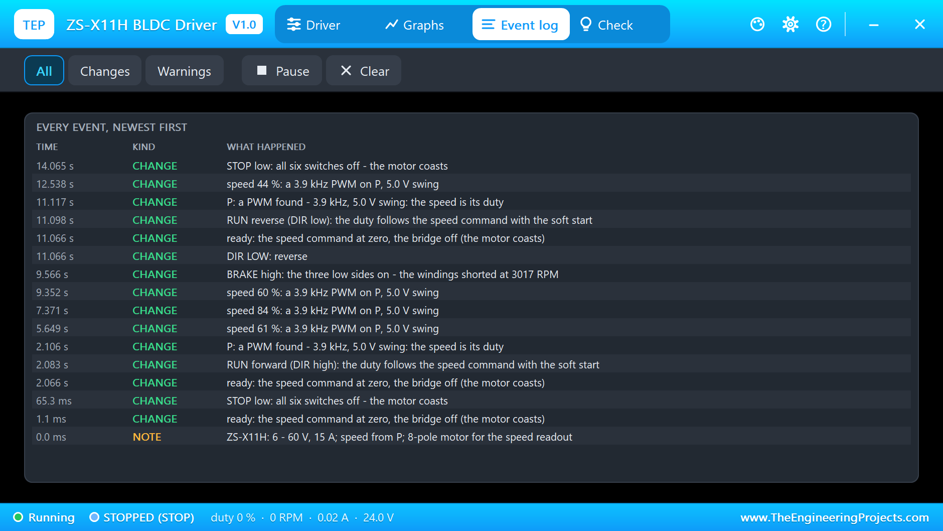
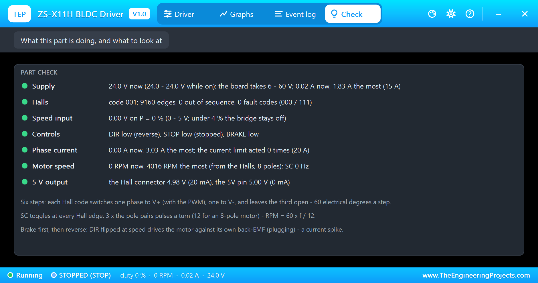
The Event log keeps every change of state and every new speed command with its source: the PWM found on P, the duty raised under the load and lowered after it, the brake, DIR, STOP. The Check page sums up the supply, the Halls and their steps, the speed input, the controls, the phase current, the motor's speed and the 5 V outputs.
Try It Yourself
- Set JUMPER to ON and POT to 50: the onboard potentiometer sets the speed and P is ignored.
- Type
f 2500, thenr 1000without a brake: DIR flips while the motor turns forward, and the board drives it against its own back-EMF. - Swap the Hb and Hc wires: the Hall steps come out of order and the motor runs rough or stalls.
- Double KP and KI in the sketch: the load steps settle faster, but the speed starts to ring.
- Disconnect the Hall +5V: the board reports a HALL FAULT and turns the bridge off.
Ideas to Extend the Demo
- Add a potentiometer on A0 for the target speed, and a button for the brake.
- Watch the supply current and lower the target when it passes a limit, a simple current loop around the speed loop.
- Drive two motors with two boards and keep them at the same speed.
Your Own Sketches
The demo sketch is in the zip file, and you can change it in the Arduino IDE. New to Arduino? Start with our Arduino Tutorial for Beginners. Export the compiled binary, and set the UNO's PROGRAM property to the new file. Our guide on How to get the HEX file from Arduino shows you where the file ends up.
Things to Know Before Using a Real ZS-X11H
- The jumper decides the speed source: off for P, on for the potentiometer.
- Brake before you reverse: flipping DIR at speed is plugging, a current spike for the board and the motor.
- Match the Halls and the phases: the motor's A, B and C to Ha, Hb, Hc and to MA, MB, MC; if it runs rough, swap two phases and two Halls together.
- Mind the supply and the heat: stay within 60 V and the motor's rating, add a fuse, and a heat sink for currents over a few amperes.
Troubleshooting
- HALL FAULT: the code 000 or 111: the Hall cable is loose, or its +5V or GND is missing.
- Hall steps out of sequence: Ha, Hb and Hc are not in the motor's order.
- The motor does not start but the board shows a duty: STOP is low, BRAKE is high, or the motor is stalled; after 2 s the board reports a LOCKED ROTOR.
- No speed from P: the jumper is on, or the PWM is under 2.5 V; the pop-up shows the source it uses.
- The part is not simulated:
TEPZSX11H.DLLis missing from MODELS and from the project folder.
Limitations of the Simulation
- The bridge is averaged: the PWM ripple, the dead time and the MOSFETs' heat are not simulated.
- The current limit (20 A) and the switch resistance (12 mohm) are our figures; the board's own current sensing is not published.
- Sensorless running is not modelled: the board needs the Halls.
- Arduino is a name of Arduino; this library is not made or endorsed by Arduino, Labcenter or any board seller.
- Tested in Proteus 8.5 in November 2026 (the demo as shipped). Proteus 7 is not supported.
So, that was all about the ZS-X11H BLDC Driver Library for Proteus Simulation. I hope it helps you drive brushless motors in a simulation first: the six steps from the Halls, a speed from P, DIR, STOP and BRAKE, and a speed loop that holds its target under a load, with a pop-up that shows every switch and every current. If you have any questions, ask in the comments and I will help you out. Till the next tutorial, take care and have fun!