Today, we are gonna have a look on How to Interface Ultrasonic Sensor with Arduino . Few days ago, I have posted a complete tutorial on How to Use Ultrasonic Sensor Library in Proteus and later I have posted different examples on How to Simulate Ultrasonic Sensor in Proteus . Those posts were about Proteus Simulations and weren't about hardware interfacing, so I thought today let's interface it in hardware. Simulation is a good starting point for projects but they are really far away from real world. It happened to me a lot of times that my simulations are working perfectly fine but when I design the same circuit in hardware then it says no I am not gonna work. :) So, the bottom line is never trust simulations, unless you properly test it on hardware. So, today I am gonna interface an Ultr ...
Update: I have updated the code and removed the bug. Thanks for informing. Now this code will work perfectly. Buy This Project Hello friends, hope you all are fine and having good health. Today, as the name suggests, I am gonna post on how to Receive SMS with AT Commands using Sim900 and Arduino. I have already posted a tutorial on How to Send SMS with Arduino UNO and Sim900 , so now we are gonna check the opposite. Sending SMS is quite easy, you just need to write some AT commands and write the message you wanna send and hit the Cntrl + Z and it will be sent. But receiving a text message on your SIM900 shield is a bit difficult because now you need to place a check when user will send a message. So, ideally whenever anyone send a message to your SIM900 module, you should get notified. Tod ...
Hello friends! In this guide, we will learn how to use Proteus ISIS and ARES, starting with a simple circuit and gradually moving toward microcontroller simulations and PCB design. I have kept the original tutorial collection so that you can follow a lesson in detail whenever you reach that stage. Our goal is to understand the complete development process. We will draw a circuit, calculate what it should do, simulate its behavior, examine signals with instruments and then prepare a physical board layout. Each stage answers a different question, so a successful simulation is one step in the process rather than the final proof of a finished product. If you are new to Proteus, follow the sections in order. If you already use it, choose the topic you need from the linked lessons. Some screensh ...
Hello friends! In this tutorial, we will learn how to program a PIC microcontroller with code compiled in mikroC PRO for PIC, using a PICkit 3 programmer. The useful idea is simple: mikroC builds the firmware, and Microchip's programming software loads the resulting HEX file into the selected device. The original project behind this lesson required mikroC, while the available programmer was a USB-connected PICkit 3. Moving from a serial-port programmer to PICkit 3 made the laptop connection easier, but the compiler and programmer still needed a common file format. The HEX file provides that connection without requiring us to compile the project again in another C compiler. We will preserve the original MPLAB IDE screenshot sequence, explain what each step does, and cover the important chec ...
Hello friends, I hope you are doing well. In the previous tutorial, we studied the working principle of a relay . Today, we will connect a 12 V relay to a PIC18F4550 microcontroller through a ULN2003A driver. A relay coil needs more voltage and current than a microcontroller pin should provide. It is also an inductive load, so it produces a voltage transient when switched off. The ULN2003A solves these interface problems by providing seven low-side Darlington drivers and seven internal clamp diodes in one package. The key point is that the ULN2003A does not convert a 5 V logic signal into a 12 V output. The 12 V energy comes from a separate 12 V supply. A logic high merely turns on one internal driver, which connects the low side of the relay coil to ground. We will examine that current pa ...
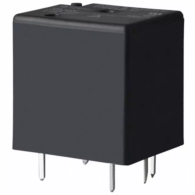
Hello everyone! I hope you are doing well. In this tutorial, we will study the relay from its basic construction to practical selection and control. A relay allows one electrical circuit to operate contacts in another circuit. This makes it useful when a low-power controller must switch a different voltage, a larger load or an electrically isolated circuit. We will focus first on the common electromechanical relay because its moving contacts make the operating principle easy to understand. We will then compare electromagnetic, reed, solid-state, thermal and hybrid relays, calculate coil current, discuss contact ratings and examine a safe microcontroller driver. A relay is often described as an automatic switch, but that short definition hides several important details. The coil and contact ...
Hello friends! In this tutorial, we will design an LED blinking project using the PIC16F877A microcontroller. It is a simple project, but it introduces several ideas that appear in almost every embedded system: configuring an I/O port, choosing an oscillator, building a reset circuit, calculating LED resistors, generating a time delay, compiling a program, and loading the resulting HEX file into Proteus. We will connect eight LEDs to PORTB and switch the complete port between logic low and logic high. Once this basic version works, you can change the output patterns and timing to create a running light, binary counter, or status display. The important objective is to understand why every connection and every program statement is present. Figure: The original simulation shows the PORTB LED ...
Hello friends! We have already covered the Introduction to XBee Module and Interfacing of XBee with Computer . In this tutorial, we will connect our configured radios to two Arduino UNO Rev3 boards and use a pushbutton on one board to control the built-in LED on the other. We will build the project in stages. First, we will establish the power and serial connections. Next, we will define the messages sent between the boards. Finally, we will write separate sender and receiver sketches and examine how they handle button bounce, incomplete messages, and a lost wireless connection. The example assumes two compatible radios already configured for transparent serial communication at 9600 baud. The address values carried forward from the previous lesson apply to classic S1 802.15.4 firmware. Rad ...