Hi Mentees! I hope you all are having a Productive Day. In our previous lecture, we discussed the DLD Basic Logic Gates and simulated them in Proteus. Today, we are going to use these standard logic gates and will design another logic gate named NOR Gate and will also simulate it in Proteus.
In this tutorial, we'll learn the following concepts:
What is a NOR Gate?Why NOR is called Universal Gate?
How to derive other Gates through NOR Gate?
Advantages of NOR Gate.
Let's begin the exploration:
What is a NOR Gate?"NOR gate is designed by inverting the output of an OR Gate, so it gives a HIGH output, only when all the inputs are LOW."In simple words, a NOR Gate has an OR Gate followed by the NOT Gate, as shown in the below figure:
...
Hi Learners! I hope you are having a productive Day. Welcome from the Team of The Engineering Projects. The digital logic circuit that we are learning today is 4-Bit Full Adder. In our previous tutorial, we designed 2-Bit Full Adder using Logic Gates in Proteus software. Today, we are going to design & simulate 4-Bit Full Adder using Logic Gates in Proteus.
We will discuss the following topics in today's lecture:
What is Adder?
What is Full Adder?
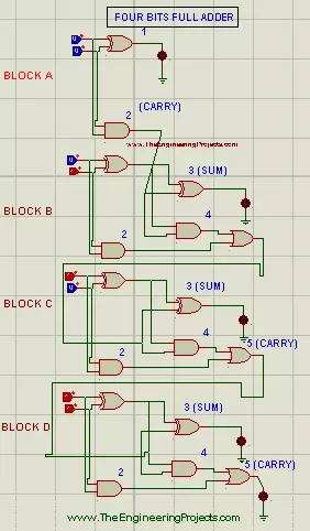
Working Principle of 4-bit Full Adder.
Simulation of four-bit full Adder in Proteus ISIS.
What is Adder?
Let's recall the Adder Definition from our previous lectures:
Adders are Digital Logical Circuits, specially designed to add two or more binary numbers or bits.In the world o ...
Hello Learners! Welcome to The Engineering Projects. In the previous tutorial, we discussed the first universal gate i.e. NOR Gate and simulated it in Proteus. Today, we are going to focus on the second universal gate i.e. NAND Gate. We will also derive basic logic gates from the NAND gate, to prove its universality.
Today, we'll seek the answers to the following questions:
What is a NAND Gate?What is a Universal Gate?
NAND as a Universal Gate.
NAND Gate as Universal Gate in Proteus ISIS.
Let's get started:
What is a NAND Gate?
A NAND Gate is designed by inverting the output of AND Gate and thus it gives a LOW output when all of its inputs are HIGH, otherwise, it's HGIH.In order to design a NAND gate, simply place a NOT gate in ...
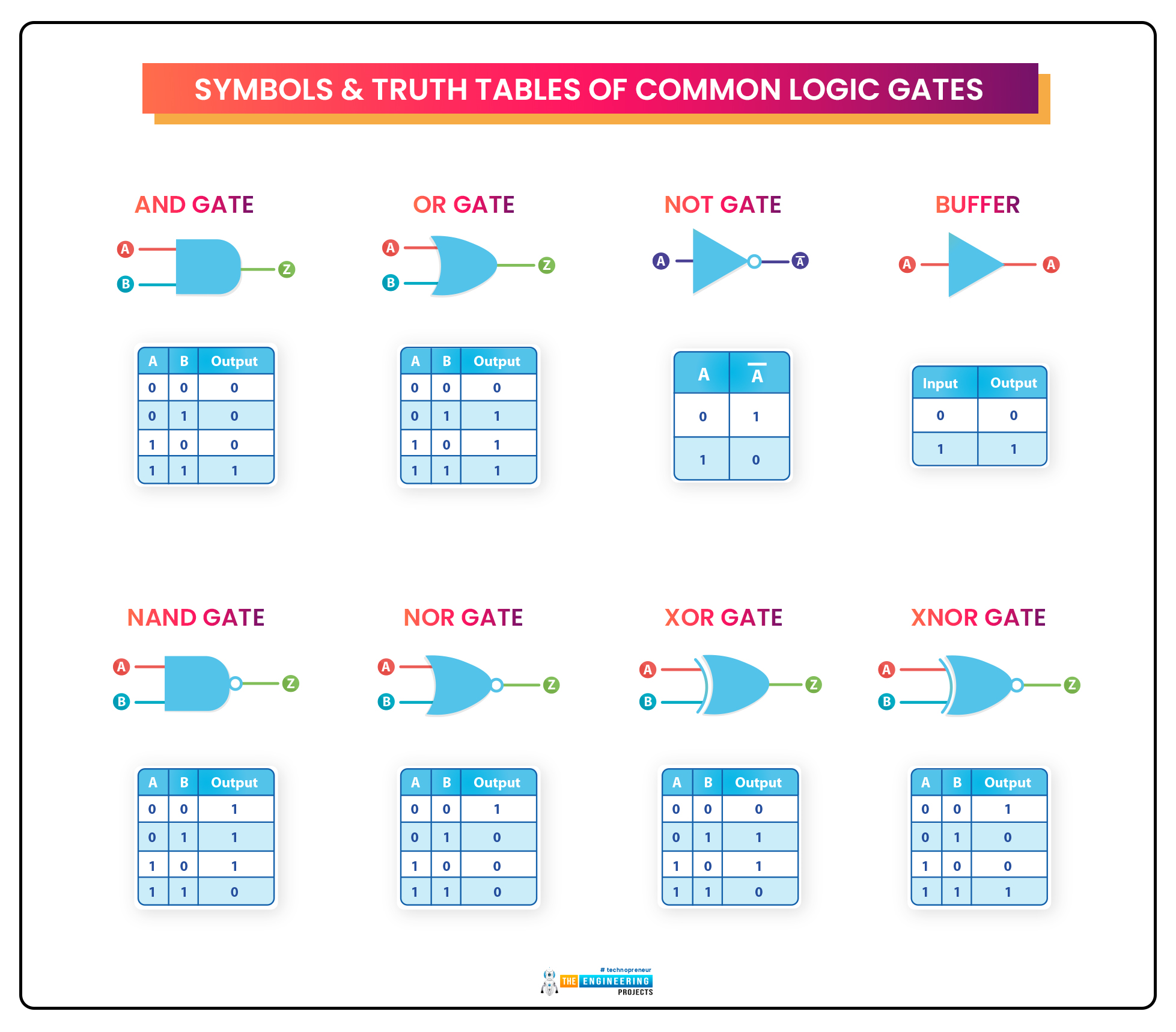
Hello Mentees! I hope you all are doing well. In today's article, we'll learn about the very basic pillar of Digital Logic Circuits i.e. Logic Gates. As we know, the digital world depends on Boolean digits either 0 or 1. So, there's always a need to perform different operations on these boolean numbers i.e. addition, subtraction, multiplication, shifting etc. In order to perform these operations on the binary signals, we use Digital Logic Gates in DLD circuits.So, let's have a look at What is a Logic Gate:What is a Logic Gate?
Logic Gates are designed to perform a specified operation(i.e. addition, bit shift etc.) on the input signals and generate the output signal.
For example, a simple NOT gate takes a single binary input and returns its inverse in the output, i.e.If Input is 0, the Ou ...
Hello Learners! welcome from the team of The Engineering Projects. We hope you are having a productive day. We are working on a series of Blogs based upon the core knowledge about Digital Logic Gates and Circuits. In this tutorial, we'll know about the SR Flip Flops and after brief introduction we will simulate SR Flip Flops in Proteus. Let's have a glimpse on the topics of today:
What are Flip Flops?
What are the types of Flip Flop?
How does we design the Truth Table of SR Flip Flops?
What are further classes of SR Flip Flips?
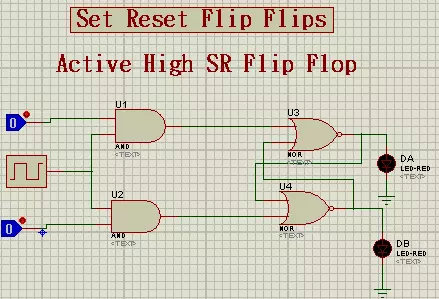
Implementation of SR Flip Flops in Proteus.
Flip Flops
Flip Flops are extremely important Circuits of Digital Logic Design. We Introduce the Flip Flops as:
"Flip Flops are type of sequential Logic Circuit that co ...
Hello Pupils! I welcome you to The Engineering Projects. I hope you are having a good day. In our previous lectures, we simulated almost all the DLD Logic Gates i.e. AND, OR, NOT, NOR, NAND, XOR and XNOR. I hope now you must have a complete understanding of the logic gates and their working.
Now, it's time to have a look at the reason for inventing these logic gates. These DLD logic gates are used to design different numerical modules i.e. adder, subtracter, multiplexer, de-multiplexer, encoder, decoder etc. These arithmetic modules are normally used in electronic products i.e. a simple microcontroller has numerous adders/subtractors for properly calling the registers' addresses.
So, from today onward, we are going to discuss these applications of logic gates one by one. Today, we wi ...
Hello Pupils! I welcome you to The Engineering Projects. I hope you are having a good day. In our previous lecture, we discussed Half-Adder Circuit Designing with XOR and AND logic gates. Today, we are going to design the same circuit using universal logic gates i.e. NOR and NAND gates.We are going to learn the following topics, in today's lecture:
What is Adder?
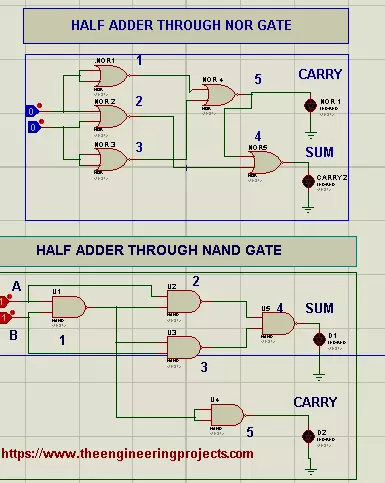
What is Half Adder?How can We make Half Adder Circuit through NAND Gate?
How can We make Half Adder through just NOR Gate?
Hence without wasting time, Let's find all the Answers.
What is Adder?As we discussed in the last lecture, the DLD Adder is a simple electronic circuit, used to add binary numbers in bit form.There are two types of DLD Adders, named:
Half Adder
Full Adder
In this article, we'll f ...
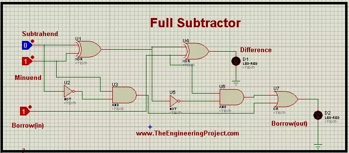
Hello mentees! Welcome on the behalf of The Engineering Projects. We are here with a new lesson about the Digital Logic Circuits. Logic Circuits work as heart in many electronic Circuits. The topic of today is Full Subtractor in Proteus and you will find the answers of the following questions:
What are 2 bit Full Subtractors?
How can we design the Truth Table of 2 bit Full Subtractor?
How can we implement the 2 bit Full Subtractor in Proteus ISIS?
You will also learn some important chunks of information in the DID YOU KNOW sections.
2 bit Full Subtractors
A full Subtractor works really well in the processor. We’ll talk about it function but before that have a look at its definition:
2 bit Full Subtractor is a Combinational Logic that co ...
Hey Mentees! Welcome from the team of The Engineering Projects. We hope You are having a reproductive day. To add more reproduction, let's learn another Logical Circuit from scratch.
In this Tutorial, we'll grasp the following topics:
What are D-Type Flip Flop?
Which is the IC of D Flip Flop in Proteus ISIS?
How is the working of D Flip Flop?
How can we design the Truth Table of D Flip Flop?
How can we Perform the formation of D Flip Flops in Proteus ISIS?
Moreover, we'll have small chunks of information in DID YOU KNOW Sections. At this instance, Let's start the learning.
D-Type Flip Flops
D-Type Flip Flops are important Logical Circuits and we Introduce it as:
"The D-Type Flip Flop is a type of Flip Flop that captures the value of D ...
Hey Pals! We hope you are doing Great. Today, we are going to design another application of DLD Logical Gates i.e. Half Subtractor. In our previous lectures, we covered Adders in detail, where we studied both Half Adders & Full Adders. Now its time to discuss its reciprocal i.e. Subtractors.
In this session, we'll seek the answers to the following topics:
What is Half Subtractor?
Working Principle of Half Subtractor.
Truth-table of Half Subtractor.
Simulation of Half Subtractor in Proteus using three Logic Gates.
Designing of Half Subtractor with NOR gate.
So, let's get started:
What is Subtractor?The functionality of Subtractors is exactly the opposite of Adders(we discussed in previous lectures) and defined as:A Subtractor is a simple DLD Electronic circuit, d ...