Hi friends, I hope you are very well; today in this tutorial, we will practice conditional jumping for performing some code at the occurrence of some conditions. Like any other programming language, jumping is one of the most common approaches to transfer the execution from its sequential mode to run different processes or instructions marked by a label and bypassing the lines of codes in between the last executed transaction before the jump instruction and the labeled instruction whom the program is going to move to. The good thing about this technique is shortening the scan cycle of the program due to not running the whole program. However, using jumping techniques in coding is very dangerous. It would help if you were careful of missing some op ...
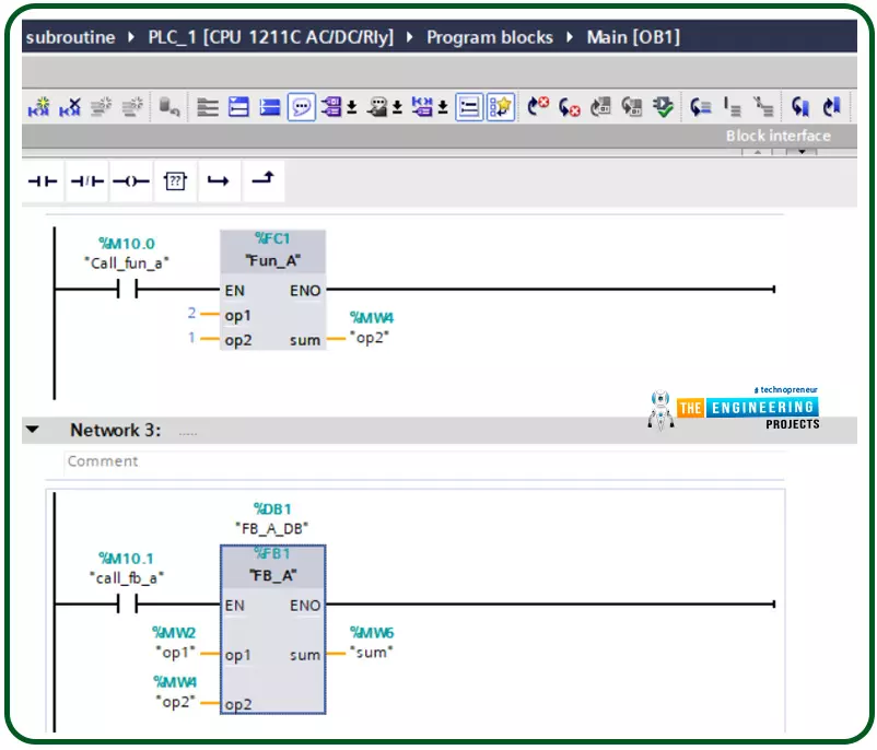
Hello friends, after completing that basic part of ladder logic programming, let us today go through one topic which is not essential to know to complete a PLC ladder program but it is important t have our code readable program and reusable pieces of code. That could happen by using what so-called a subroutine. So what is a subroutine? Well, it is a piece of code that includes a few rungs to perform specific tasks. that piece of code can be reused numerous times through the program when we need to call it for performing that task. That subroutine enables us to structure our code like building blocks so that the program will be readable very easy and also reusable later in other projects. The idea of dividing the program into routines to apply the divide and conquer technique is very crucia ...
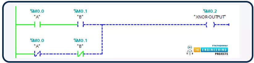
Hello friends! I hope you are all very well! I am so happy to meet you today to continue learning and practicing PLC ladder logic programming. In an earlier part, we already have gone through the very basic logic gates of “AND”. “OR”, and “NOT”. Today we are going to resume the simulation of logic gates. We have started and gone through simulating the basic logic gates which are “AND”, “OR”, and “NOT” as they are the most important basic logic gates by which we can form other logic gates. However, because the logic of large-scale projects is getting more and more complicating, a lot of time we have to use the other functions to do tasks faster. For example, we have shown in the logic gates article that, XOR can be used to compare two inputs and ch ...
Hi friends and hope you are doing very well. Today we would like to take one tutorial which is very essential in the industry which is analog input processing for handling analog measurements of physical signals like temperature, humidity, pressure, distance, flow and level of liquids, etc. Typically, sensors produce two types of analog signals to represent the equivalent measured signal which is current and voltage signals. The currently produced signals would be within the range of 4-20 mAwhile voltage signals are in the range of 0-10 v. because, that output signals represent physical signals, the limits of output signals are 0 to 10 v for voltage based sensors and 4 to 20 mA for current-based sensors, these values should be scaled to represent ...
Hello friends, all of us know that PLCs are nothing but the smartest migration from relay logic control to programmable logic control. Also, you know clearly that, logic is the heart of any programming language, and the same is applied to ladder logic programming. Bitwise operators represent the logical operations including the basic logical operations like AND, OR, and NOT and the derived logical operations like NAND, NOR, and XOR. in most cases, for each bitwise operator, there are inputs based on which the output can be decided. Some of these bitwise operators have two inputs and some have only one input. In this article, we are going to present how we can use these bitwise logical operators and their instructions with examples and practice using the PLC simulator.
Logic Gates ba ...
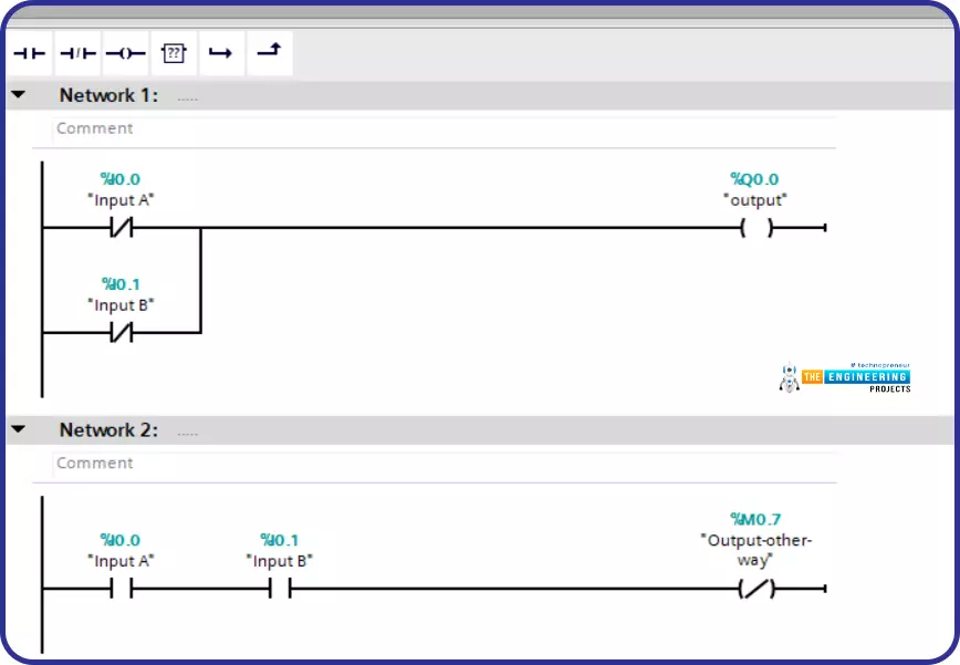
Hello friends, I hope you all are fine. Today, we are starting a new tutorials series on Ladder Logic Programming, used in PLC. It's our first tutorial in this series, so we are going to have a look at the detailed introduction to PLC and ladder logic. After welcoming every one of engineers, technicians, students, and hobbyists who have come to read this article willing to learn PLC programming, I would like to introduce one of the most used programming languages of PLC. The language we introduce here is a visualized language that connects and combines graphical symbols in logical flow same as the way we wire electrical circuits and that is the secret behind its simplicity not only in implementation but also in diagnosing problems.
Ladder Logic Pro ...
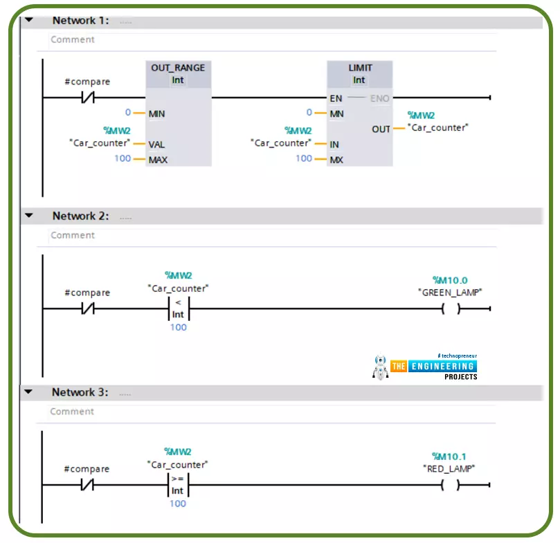
Hi friends. Today we are going to go through one of the most commonly used topics in writing ladder logic programming which is using comparator operations. This includes the logical and mathematical comparison between variables to decide where the logic goes.
There are many comparator operations like equal (==), not equal (<>), less than (<), greater than (>), less than or equal (<=), greater than or equal (>=). All these comparator operations might be used in different logic scenarios while writing a ladder logic program. In this tutorial, we are going to go over each operator showing the input operators and output as well. In addition, we will practice some examples with the simulator to familiarize how to use them flexibly whi ...
Introduction
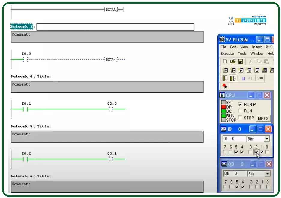
Hello friends, I hope you are doing very well. Today we are going to learn and practice the master control reset (MCR)! So what is that MCR? Well! This is a tool you might use to control a group of devices with one push button for performing fast emergency responses with one click for a group of devices in one zone. In another word, you divide the program into zones and put this zone between a master control to control their operation as one unit by one contact. This technique is useful for applying emergence stops and also protecting some equipment by applying a safety restriction to not operate when that condition is in effect.
The concept of the master control reset (MCR)
Figure 1 shows the master control relay in a ladder logic showing a couple of rungs between the ma ...
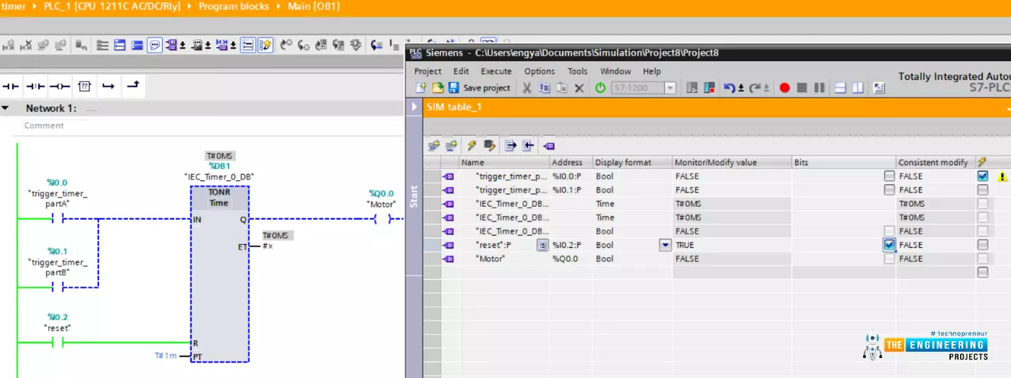
Hello friends! I hope you are doing very well, today we have a very crucial topic which is “timers”. Yes! Exactly like what comes to your mind. For running equipment i.e. motor at a specific time and/or for some amount of time we need timers. Timers are used even before PLC in classic or relay logic conventional control. However, there is a big difference between capabilities and limitations between using physical timers in classic or old fashion relay logic and using software timers in PLC. By completing this article you will be able to know what are timers and their types and applications. In addition, we are going to show off how to use timers in ladder logic programming with examples.
What are timers used for in industrial applications?
Well! ...
Hi friends, today we are going to learn one of the most important instructions in the PLC ladder which is MOVE instruction by which we can move data between different memory storage including input, output, marker, and variables. Also, data of different data types and sizes can be transferred from source to destination and source memory locations. For example data types including char, string, integer, floating, time and date can be transferred between source and destination. Memory location like input, output, and marker memory area can be acting as source or destination. Furthermore, a mask can be utilized to customize and control the part of data to be transferred between source and destination. In that move with a mask, the instruction uses a source address, a destination address, and ...