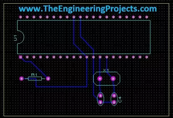
Hello friends! Today we will move from a circuit diagram to a printed circuit board using Proteus ARES. We will use a small PIC16F877A circuit so that placement, connectivity, and routing remain easy to follow. The same sequence of decisions applies when you later design a larger board. Proteus schematic capture describes which component pins belong to each electrical net. PCB layout turns those connections into physical pads and copper tracks. A completed route is useful only when the footprint, pin mapping, power connections, and manufacturing rules are also correct. We will follow the original illustrated workflow: prepare the schematic, transfer its connectivity, define the board edge, place components, and route the board. We will then add the checks needed before sending a design for ...
Hello friends! Today we will control a servo motor with the PIC16F877A and observe its movement in Proteus ISIS. We will begin with the three servo connections, understand the command waveform, and then write a small program that selects positions using two pushbuttons. In the previous tutorials, we explored DC motor direction control and stepper motor sequencing . A positional hobby servo is different because the motor, gearbox, position sensor, and controller are already assembled together. Our PIC requests a position rather than switching the motor windings itself. We will keep the original PIC and button arrangement, but use a repeated control pulse with a sensible frame period. Along the way, we will separate what the simulated angle display tells us from what a physical servo must be ...
Hello friends! In the previous tutorial, we controlled the direction of a DC motor in Proteus . Now we will work with a stepper motor, where rotation depends on applying an ordered sequence to the windings. We will begin with the original six-wire simulation, inspect the sequence manually, and then explain how a microcontroller and driver can generate it. The original screenshots use Logic State sources to make individual winding states visible. They are useful for understanding the sequence, but they are not a physical driver circuit. We will preserve the images and add the missing distinction between simulated logic sources, microcontroller outputs, and the winding-current path. By the end, you should understand unipolar and bipolar wiring, wave drive and half stepping, direction reversa ...
Hello friends! In this tutorial, we will design a DC motor control demonstration in Proteus ISIS and then connect its control logic to a PIC16F877A. We will begin by observing how voltage polarity changes the direction of a simulated motor, then explain the driver stage needed between a microcontroller and a physical motor. The original article used Logic State sources and a simplified direct connection to illustrate direction changes. We will preserve those screenshots, but label their purpose clearly. Logic sources and PIC output pins are not substitutes for a motor power driver. The updated practical interface uses an L293D bridge example, with separate logic and motor supplies. We will also correct the relationship between the original schematic and code, add explicit stopping behavior ...
Hello friends! In this tutorial, we will design an LED blinking project using the PIC16F877A microcontroller. It is a simple project, but it introduces several ideas that appear in almost every embedded system: configuring an I/O port, choosing an oscillator, building a reset circuit, calculating LED resistors, generating a time delay, compiling a program, and loading the resulting HEX file into Proteus. We will connect eight LEDs to PORTB and switch the complete port between logic low and logic high. Once this basic version works, you can change the output patterns and timing to create a running light, binary counter, or status display. The important objective is to understand why every connection and every program statement is present. Figure: The original simulation shows the PORTB LED ...