Hello friends, hope you all are healthy, wealthy and wise. Today's topic is about the control of stepper motor. In the last post we have seen How to control DC motor in Proteus, and now we are gonna see How to design a Stepper Motor Drive Circuit in Proteus ISIS. Stepper motors are usually of two types and the main difference between the two is in the number of wires used to control them. Mostly stepper motors use 6 wires to control them but few of them also have 4 wires to control them. Today we will have a look on the 6 wired stepper motor.
In stepper motor, there are electromagnets which gets polarized when we supply voltage to them and depolarized when we remove the voltage. These electromagnets act as a stater and when one side get magnetize, it attracts the rotor towards it and then we need to magnetize the other side and demagnetize the previous one and in this ways if the sequence is right the motor starts moving.
Stepper Motor Drive Circuit in Proteus ISIS
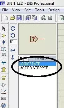
First of all, add the below two components from the Proteus library in the workspace.
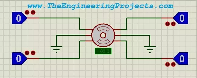
Now design the circuit as shown in the below figure:
This circuit is just for understanding purposes. Now I have added four states in the circuit, when I make any state one that stator got magnetize and the motor rotor will attract towards that stator and start moving.
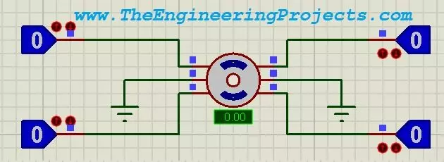
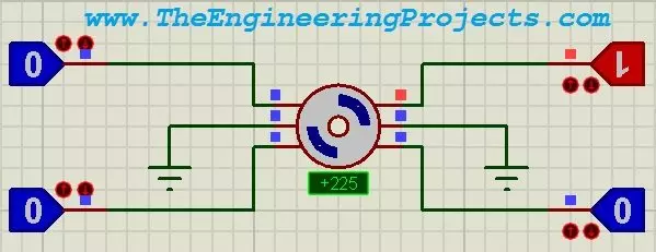
In the below series of images, I have shown the clockwise movement of motor.
Now, as you can see from the above sequence of images, the motor is moving in the clockwise direction as I am supplying voltage in the clockwise direction.
Now, if I reverse the order of applied voltage the motor will also reverse its direction and will move in the counter clockwise direction.
The speed of the motor will depend on the speed of this sequenced voltages. If you apply these voltages with delay, the motor will move slow and if you apply them fast and continuously, the motor will rotate quite fast i.e. rpm of motor will increase.
Stepper Motor Control with Microcontroller
Now, in order to control this motor using stepper motor, simply connect these wires with four pins of microcontroller and apply a sequenced voltage in programming and the motor will run quite smoothy.
I will upload the video of the stepper motor control with microcontroller soon in this post.
That's it for today and I hope now you got the idea how to design a Stepper motor Drive Circuit in Proteus ISIS. In the next post, we will have a look at How to design a Servo Motor Drive Circuit in Proteus ISIS. So, we will meet in the next post hopefully. Take care.
syedzainnasir
I am Syed Zain Nasir, the founder of The Engineering Projects (TEP). I am a
programmer since 2009 before that I just search things, make small projects and now I am sharing my
knowledge through this platform. I also work as a freelancer and did many projects related to
programming and electrical circuitry. My Google Profile+Follow
Get Connected
Comments on ‘’ Stepper Motor Drive Circuit in Proteus ISIS ‘’ ( 5 )
0
abdolhoseinghanbari
Says:
Dear sir.
L298 -Heart beat modules and c945 libraries have no archive files i will realy appreciate if i could get this library.
Thanks a lot.
Reply
100
1
vijju
Says:
If u have any pdf can u send it????
Reply
100
2
borisliberman
Says:
Dear Syed,
I will need your servicees to write program and make project to control stepper motor via Enthranet connection.
Please let me know if you are available for such project
Best regards
Boris
Reply
100
3
Says:
Yeah we can provide you the complete project. Add me on skype and we will discuss it. My Skype id is theenggprojects.
Thanks.
Reply
100
4
hamoodbinmehmood
Says:
brother will you help me in drawing a transfer curve for any transistor in ISIS as i am working on my mini project. I m from uet peshawar
Reply