Now in today's project, it can be understood from its name (Relay Control Using 555 Timer in Proteus ISIS), that we are going to operate and control a Relay through 555 Timer. First of all, if we define the relay, then we can say that 'Relay is an Electrical switch which operates Mechanically'. You should also check this Relay Simulation in Proteus to know how it works. Although some relays operate automatically but since we are working on a very basic project and we will be controlling the relay from an external mean and for this, we will use a mechanical switch. The mechanical switch is in fact a button and we can turn it ON or OFF according to our own choice. It is a very simple and easy project and most of its contents have been described in the earlier tutorials. So, I am not going into much detail and without wasting any time, let's move towards the Hardware of the circuit. But it's my personal advice, try to do design this relay control using the 555 timer project yourself and get to know the practical applications of the 555 Timer in person. You can also download the complete simulation of above described tutorial by simply clicking on the button given below:
Download Project Files| Where To Buy? | ||||
|---|---|---|---|---|
| No. | Components | Distributor | Link To Buy | |
| 1 | 555 Timer | Amazon | Buy Now | |
| 2 | LEDs | Amazon | Buy Now | |
| 3 | Resistor | Amazon | Buy Now | |
Relay Control Using 555 Timer in Proteus ISIS
- First of all place all the components in your Proteus workspace as shown in the image given below:

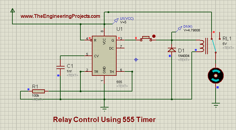
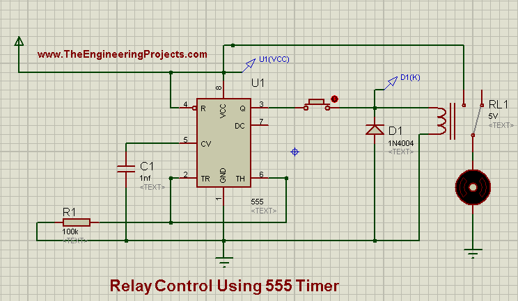
- Now connect supply voltage (+5 volts) to Vcc pin of 555 Timer.
- At the output pin of 555 Timer, which is pin # 3, we will connect our load. By load we mean a 5 volts relay and a simple DC motor is connected next to the relay.
- As I told you earlier that we are using a manual relay, so a simple push Button is also connected between pin # 3 and relay.
- If you have connected all the electronic components in their exact place, then the final simulation will look like as shown in the image given below:

- If you notice the image closely, then you will observe that a Diode is also connected in parallel with the relay coil.
- A Relay contains a coil. When the voltage source is applied across one end of the Relay and the other end is connected to the ground, then the relay gets energized. And when we remove the source voltages then, it still remains energized and the stored charge tends to flow the reverse current.
- The reason to connect the Diode is that it blocks the reverse current and only allows the forward current to pass through it.
- Now run the simulation, if the button is kept in the OFF state then, the voltage will appear across the Relay but it will not operate. To run the load, which is Motor, in this case, we will have to turn the switch ON. This can be seen in the image given below:

- As you can see in the above image, when the switch was in an ON state, the relay gets no signal and doesn't operate. As we move the switch from ON state to OFF state, the relay gets the signal and it starts to operate the load.
- Now after reading today's post, you must have a look at Relay Interfacing with Microcontroller which is an advanced tutorial and the benefit of a microcontroller is that now you can control your relay any way you want.
- Other exciting tutorials on 555 Timer include Seven segment Control using 555 timer and Servo Motor Control using 555 Timer.
- I have created a small video for this tutorial in which I have shown how to do relay control using 555 Timer, I hope you are gonna like it:


