Hello everyone! I hope you will be absolutely fine and having fun. Today, I am going to give you a detailed Introduction to ULN2003. We will also discuss the ULN2003 Datasheet, Pinout, Circuit Diagram & Proteus Simulation. If you have ever controlled any motor (i.e. DC Motor, Stepper Motor etc.) with a microcontroller (i.e. PIC, Arduino etc.), then you must have heard about drivers. Why do we need to use drivers? We use drivers (to control motors) because of two reasons.
ULN2003 Simulation Libraries
Latest library: 28BYJ-48 Stepper Motor and ULN2003 Driver Library for Proteus V1.0 (October 2026)
Other motor drivers: L298 · L9110S · TB6612FNG · BTS7960 · A4988 / DRV8825 · PCA9685 Servo · Relay Module · 30A Brushless ESC · TB6600 Stepper Driver · 60A Brushed ESC · DRV2605L Haptic Driver · ZS-X11H BLDC Driver · SimpleFOC Mini Driver · AC Dimmer Module · TMC2209 Stepper Driver · DRV8833 Motor Driver · L293D Motor Shield
Motors: SG90 Servo · TT Gear Motor · 28BYJ-48 Stepper · NEMA 17 Stepper · MG996R Servo · N20 Encoder Motor · JGA25-370 Encoder Motor · FS90R 360 Servo · 130 DC Motor · A2212 Brushless · X27.168 Gauge · Analog Panel Meter · DC Tachogenerator · LM393 Speed Sensor · MG90S Servo · DS3218 Servo · L12 Linear Servo · JGB37-520 Motor · RS-775 Motor · JGY-370 Worm Motor · 12V Linear Actuator · Coin Vibration Motor · Mini Submersible Water Pump · 12V Peristaltic Pump · 4-Pin PC Fan · 12V Push-Pull Solenoid · NEMA 23 Stepper Motor · Micro Linear Stepper · TYJ50 Synchronous Motor · Quartz Clock Movement · Air-Core Gauge · Electromechanical Counter · Split-Flap Display · Electric Bell · Wind Turbine · 8520 Coreless Motor · Car Wiper Motor · Car Door Lock Actuator · 12V Solenoid Water Valve · 12V Holding Electromagnet · Mini Air Pump · Planetary Gear Motor · 540 RC Motor · LRA Vibration Motor · 42BLF Hall BLDC Motor · 2204 Gimbal Motor · 120mm 230V AC Fan · NEMA 17 Closed-Loop Stepper · NEMA 17 Linear Stage · Pan-Tilt Bracket · 4-DOF Robot Arm
Helping Tools
- Serial Monitor Advance: a serial terminal window for the UART of your board
- Serial Monitor Expert: the serial monitor with extra debugging tools
- LCD Library for Proteus V3.0: 16x2, 20x4 and I2C LCDs to show your readings
- First: Microcontrollers operate at 5V while motors operate at different voltages (5V, 12V, 24V etc.).
- Second: Motors are Inductive loads thus they produce back emf, which may damage your microcontroller permanently (if not handled correctly).
Because of these two reasons, we have to use the driver in between the microcontroller & motor. There are different types of motor drivers available and ULN2003 is one of them. If we check its datasheet, then we can see that ULN2003 can handle up to 50V & 500mA. As its current rating is not that high, so it's used to control small motors. For heavy motors, we normally use relays in between ULN2003 & motor. In this case, the Microcontroller is sending a signal to ULN2003, which then forwards it to relays (connected at output). Remember, the relay is also an inductive load. So, we can control different types of loads with ULN2003 i.e. motor, relay, solenoid, actuator etc. You should also have a look at Relay Interfacing with Microcontroller using ULN2003A.
Now, let's have a look at what's inside ULN2003 in detail:
ULN2003: Definition
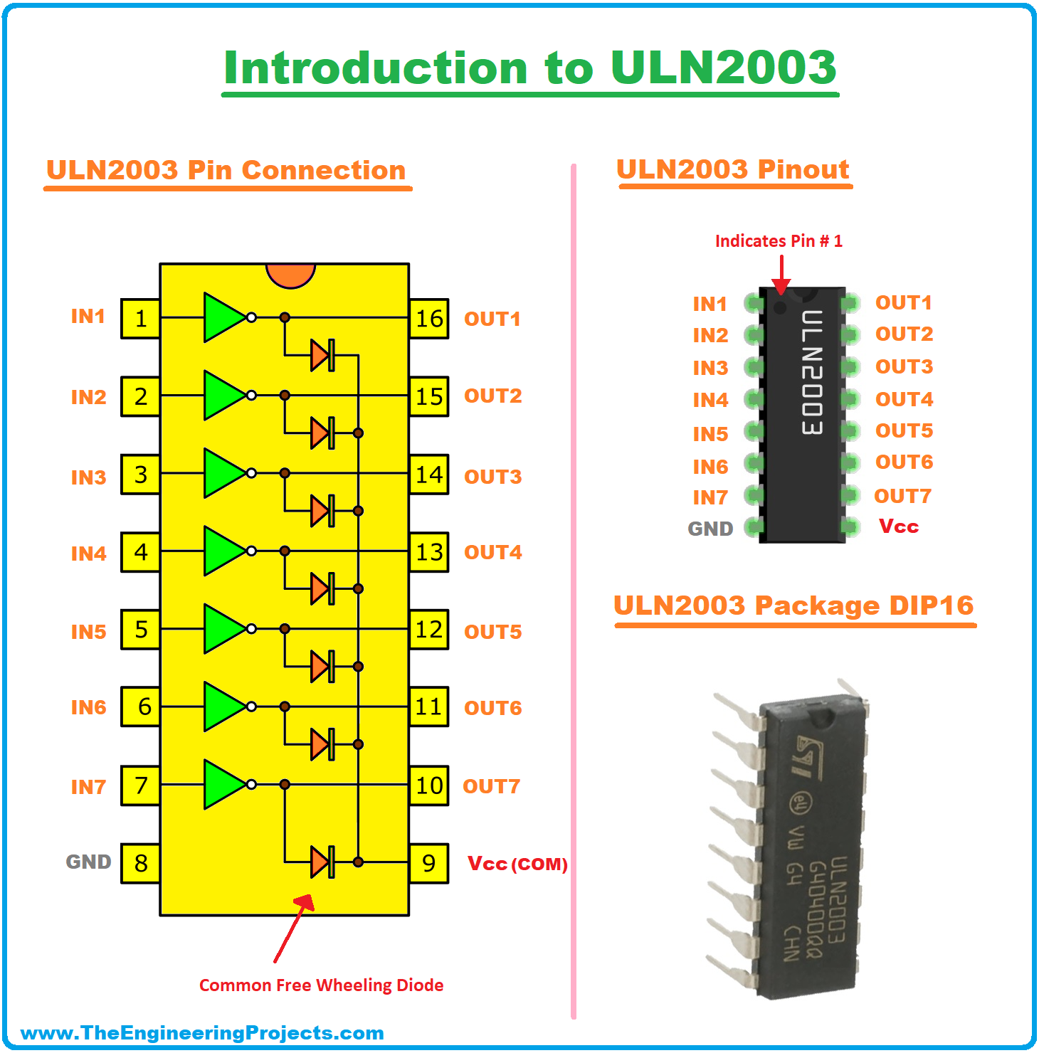
- ULN2003 is a 16 Pin IC, consisting of 7 Darlington pairs (each pair protected with suppression diode) and thus has the capability to handle a maximum of 7 loads(could be inductive).
- In simple words, we have 7 drivers in a single ULN2003 chip and thus can control a maximum of 7 loads.
- Each Darlington pair can handle a maximum 500mA load, while the peak value is 600mA.
- Similarly, the maximum output voltage of each Darlington pair is 50V.
- In the below figure, you can see ULN2003 has 16 Pins, where inputs and their respective outputs are placed in front of each other(for ease of circuit designing).
- Other than I/O Pins, we have Ground Pin where we need to provide 0V & Vcc (Common) Pin.
ULN2003 Datasheet
- Here's the link to download ULN2003 datasheet, must read it once.
- I have also given the link to a reliable source, from where you can buy ULN2003 IC.
ULN2003 Pinout
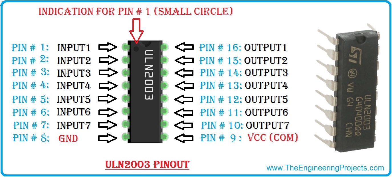
- ULN2003 has 16 pins in total:
- 7 Input pins (Pin # 1 to Pin # 7)
- 7 Output pins (Pin # 10 to Pin # 16)
- 1 Ground pin (Pin # 8)
- 1 COM pin (Pin # 9)
- ULN2003 Pinout is shown in the below figure:
ULN2003 Pin Description
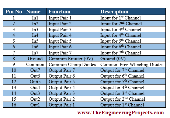
- The functions associated with each pin of ULN2003 along with pin names are shown in the table given below.
ULN2003 Darlington Pair
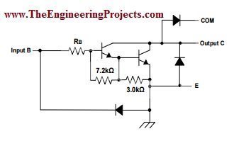
- ULN2003 consists of 7 identical Darlington pairs.
- A single Darlington pair consists of two bipolar transistors its maximum operating values are 50V & 500mA (peak 600mA).
- These two transistors of the Darlington pair have a common emitter, while their collectors are open.
- Here's the circuit diagram of a single Darlington pair, shown in the below figure:
ULN2003A Free-Wheeling Diodes
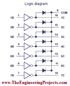
- ULN2003A has free-wheeling diodes, which protect from back emf.
- So, if we are using an inductive load (i.e. relays), then we don't need to add extra diodes if we are controlling it with ULN2003A.
- Logic Diagram of ULN2003A is shown in the below figure:
ULN2003 Features
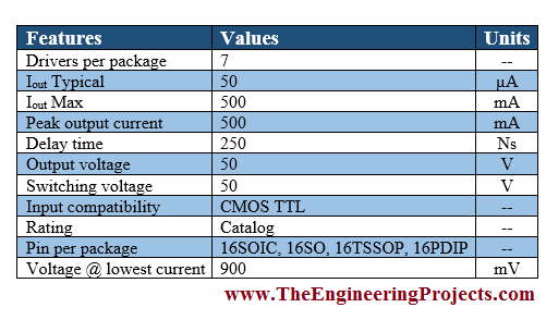
There are a lot of key features associated with the relay driver ULN2003. A few of them are given below:
- 500mA of the rated collector.
- The high output voltage of around 50V.
- Relay driver applications.
- Output clamp diodes.
- Compatible input with popular logic types.
- Some of the key features are also given in the table below for a better understanding of the working conditions of ULN2003.
ULN2003 Applications
The relay circuit driver ULN2003 has a wide range of applications in real life. Some of the major applications associated with ULN2003A are given below.
- Logic buffers.
- Line drivers.
- Relay drivers (for driving different loads).
- Lamp drivers.
- LED display drivers (display devices).
- Motor (stepper and DC brushed motor) drivers.
ULN2003 Proteus Simulation
- I have designed a simulation in Proteus ISIS for LED control using ULN2003.
- The screenshot of the simulation is shown in the figure below.
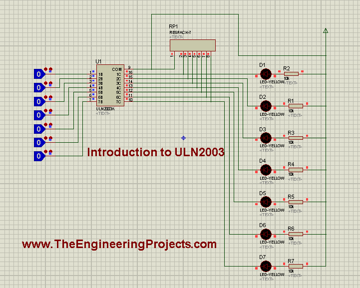
- As you can see in the above figure that I have connected Logic State at all inputs of ULN2003A and have connected Leds at outputs.
- So, now when I make the Logic State HIGH then the respective LED will also go ON.
- The running form of the above simulation is shown in the figure below.
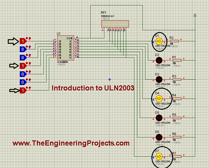
- If you change the state of the logic state from 0 to 1, the corresponding LED will be turned ON as shown in the above figure.
- You can download the Proteus simulation here by clicking on the button below.
- Just download the .rar file, extract it and enjoy the simulation.
- Here's the video in which I have shown how to use ULN2003A in Proteus:
So that is all from the tutorial Introduction to ULN2003. I hope you enjoyed this tutorial. If you face any sort of problem regarding anything, you can ask me anytime in the comments without even feeling any kind of hesitation. I will try my level to entertain you and to solve your issues in a better way, if possible. Our entire team is 24/7 here to entertain you and to solve your issues in one way or the other. I will explore different ICs in my later tutorials and will surely share them with all of you as well. So, till then, Take Care :)