Hello friends, I hope you all are doing great. Today, I am going to share the B-L475E-IOT01A Library for Proteus, so you can run a Wi-Fi and Bluetooth simulation of ST's STM32L4 Discovery kit IoT node. This board packs an STM32L475 microcontroller, a Wi-Fi module, a Bluetooth LE module, a sub-GHz radio, NFC and a whole set of sensors onto one board with Arduino Uno headers. With this library it runs your Arduino sketch in Proteus 8.5, joins a Wi-Fi network, serves web pages to a phone, reads its sensors and gestures from a Sensors window, and its LEDs and buttons work with a click.
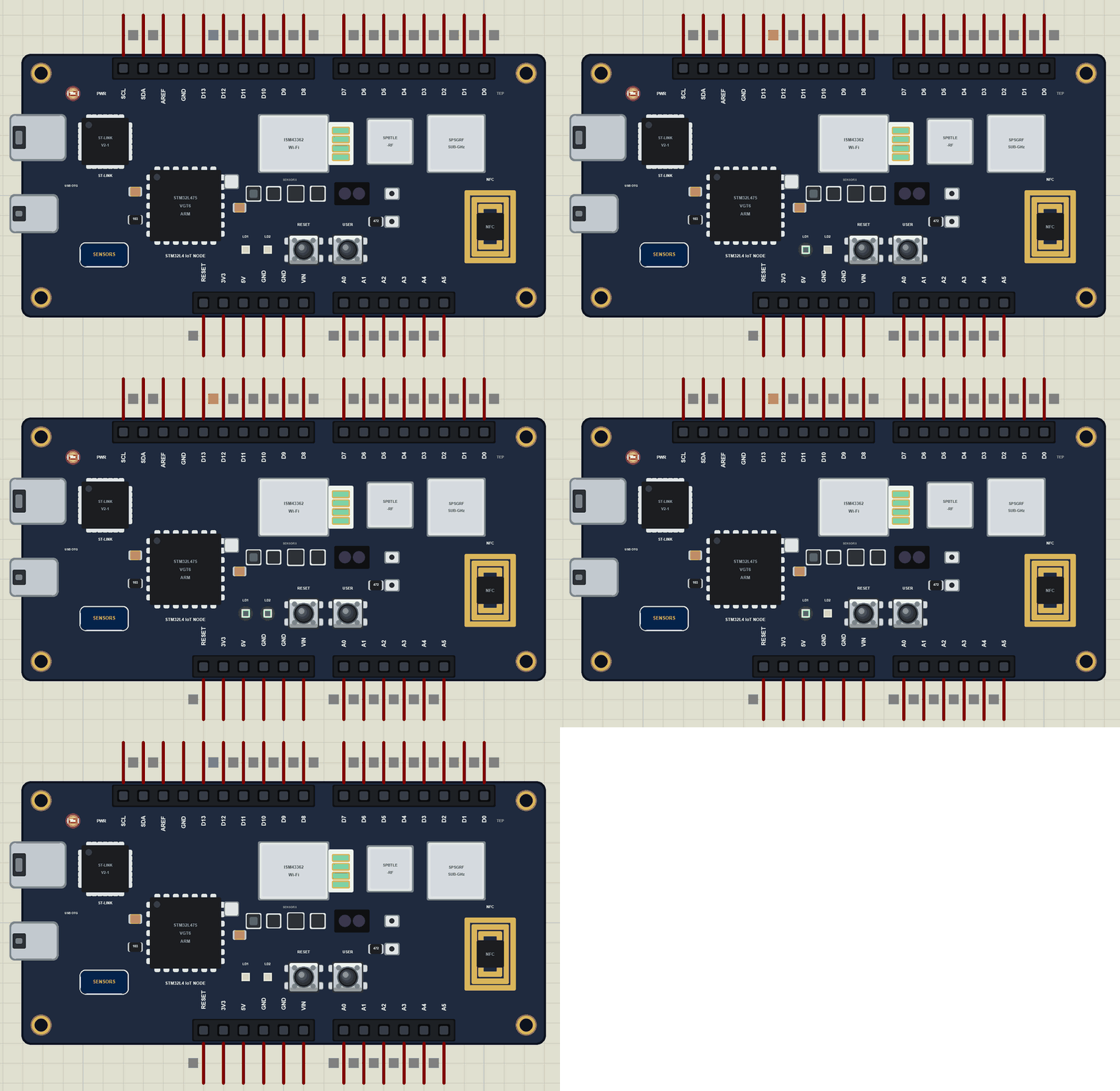
B-L475E-IOT01A Library for Proteus
Latest version: V1.0 (November 2026, this tutorial)
Other new Arduino boards: UNO R4 WiFi · Nano ESP32 · UNO WiFi Rev2 · Nano 33 IoT · UNO Q · UNO R4 Minima · Nano Every · MKR WiFi 1010 · Nano RP2040 Connect · STM32 Black Pill · Nucleo-F401RE · STM32 Blue Pill · Teensy 4.1 · Arduino Due · Arduino Leonardo · Arduino Micro · BBC micro:bit V2 · GIGA R1 WiFi · MKR WAN 1310 · Nano 33 BLE Sense · XIAO nRF52840 Sense · RAK4631 WisBlock · Nano Matter · nRF52840 DK · nRF5340 DK · nRF9151 DK · nRF7002 DK · Nordic Thingy:53 · xG24 Dev Kit · xG24 Explorer Kit · Thunderboard BG22 · SiWx917 Dev Kit
RF modules: nRF24L01 · nRF24L01 PA LNA · CC1101 · RFM69HCW · HC-12 · 433MHz RF · XBee
Temperature and weather sensors: DHT11 / DHT22 · DS18B20 · BME280 · BMP280 · SHT31 · AHT20 · BME680 · MLX90614 · MAX6675
Helping Tools
- Laptop WiFi Monitor: a laptop on the Wi-Fi of your design: a browser, a TCP / UDP terminal and ping
- Mobile WiFi Monitor: a smartphone that opens the pages of your board and sends it commands
- Serial Monitor Advance: a serial terminal window for the UART of your board
For the demo we built a Wi-Fi meeting room counter. The board sits at the door, counts the people who walk in and out with its time-of-flight sensor, lights LD1 when the room is in use and LD2 when it is full, and serves a page where anyone can check the room before walking over.
NOTICE: Proteus has no STM32L475 model and no model of the board's modules and sensors, so our team has put a lot of effort into building this board ourselves: the headers, the LEDs, the buttons, the sensors, Wi-Fi and Bluetooth LE are all our own model, and your sketch compiles with our free TEP Boards for Proteus add-on. Your feedback is the fuel that keeps us going, so please tell us what you think in the comments below. And if our free libraries help you, you can buy us a coffee. So, let's get started with the B-L475E-IOT01A Library for Proteus:
What is the B-L475E-IOT01A?
The B-L475E-IOT01A is ST's STM32L4 Discovery kit IoT node, a board made to connect sensors to the cloud with as little extra hardware as possible. Its STM32L475VG is an Arm Cortex-M4 with a floating-point unit at 80 MHz, with 1 MB of flash and 128 KB of RAM. Around it sit an Inventek ISM43362 Wi-Fi module, an SPBTLE-RF Bluetooth LE module, an SPSGRF sub-GHz radio module, an NFC tag with a printed antenna, six kinds of sensors, a Quad-SPI flash, an ST-LINK debugger with its own USB port, a USB OTG port, two green user LEDs, a blue USER button and Arduino Uno V3 and PMOD connectors.
| Part | The real B-L475E-IOT01A | In the library |
|---|---|---|
| MCU | STM32L475VG: Cortex-M4F, 80 MHz | your Arduino sketch |
| Wi-Fi | Inventek ISM43362 (802.11 b/g/n) | WiFi and WebServer on our network |
| Bluetooth LE | SPBTLE-RF module | ArduinoBLE |
| Environment | HTS221 humidity and temperature, LPS22HB pressure | Arduino_HS300x, Arduino_LPS22HB calls |
| Motion | LSM6DSL accelerometer and gyroscope, LIS3MDL magnetometer | Arduino_BMI270_BMM150 calls |
| Distance | VL53L0X time-of-flight | proximity and gestures (Arduino_APDS9960 calls) |
| Sub-GHz, NFC, microphones | SPSGRF, M24SR tag, two MP34DT01 | drawn |
| On the board | LD1 (D13), LD2, USER, RESET, ST-LINK | all of them, animated; the USB opens the monitor |
| Memory | 1 MB flash, 128 KB RAM | about 256 KB of flash, 8 KB of RAM |
Five Radios on One Board
The board is unusual because it carries almost every short-range radio an IoT product might need: Wi-Fi for a direct link to the cloud, Bluetooth LE for phones and wearables, a sub-GHz radio for long-range links at 868 or 915 MHz, and NFC for tapping a phone to pair or read data. That makes it a favourite in universities, where one board can show students the trade-offs between the radios in range, data rate and power, and for product teams who have not yet decided which link their device will use.
The STM32L4 Family
The STM32L4 series is ST's ultra-low-power line built on the Cortex-M4 with a floating-point unit. It can run at full speed for signal processing, such as filtering sensor data or running a small neural network, and then drop to sleep modes that draw only a few microamps while keeping its memory and a real-time clock. The STM32L475 on this board adds a USB OTG controller, a Quad-SPI interface for external flash and a digital filter for microphones. That mix of performance and low power is why ST chose it for an IoT node that may run from a battery or a USB power bank in the field.
Arduino Uno and PMOD Headers
The board carries the familiar Arduino Uno V3 headers, so many shields fit straight on: a motor driver, a relay board, a display. A second connector follows the PMOD standard used by FPGA boards and many small modules. Together with the five radios and the sensors already on the board, this means a research prototype often needs no soldering at all. In the simulation the Uno headers are real pins, so any of our Proteus modules can be wired to them like on an Arduino Uno, using the STM32duino pin names D0 to D15 and A0 to A5.
Time of Flight
The VL53L0X measures distance by timing a short infrared laser pulse on its way to an object and back. It reads up to about two metres with millimetre resolution and does not care about the colour of the object, unlike a simple infrared reflection sensor. Watching how the distance changes over time also lets the board recognise simple gestures, such as a hand or a person passing from one side to the other, which is how our counter tells someone walking in from someone walking out.
Where Is It Used?
The IoT node is used for cloud connectivity demos with AWS, Azure and other platforms, for smart-building prototypes such as people counting, air quality and asset tracking, in university courses on embedded systems and wireless networks, and in edge AI work with ST's tools, which use its motion sensors and microphones. Our demo is a typical smart-building device: a sensor at a door, a small decision and a web page for everybody in the office.
A simulation lets you build and test the whole logic first: the Wi-Fi connection, the web page, the counting, the LEDs and the buttons. When it works in the Proteus simulation, moving it to the real board is much quicker. For an STM32 board without radios, see our STM32 Nucleo-F401RE Library for Proteus; for another Wi-Fi board with sensors, our SiWx917 Dev Kit Library for Proteus.
How a Board Serves a Web Page
The board joins the network and gets an IP address, here 192.168.1.101. A web server listens on port 80, and each address on it, such as / or /reset, calls a small function in the sketch. The function builds the page as text and sends it back, so any phone or laptop on the same network can open it in a browser. Our Mobile WiFi Monitor is that phone in Proteus.
Features of the B-L475E-IOT01A Library for Proteus
- The board as it looks: the dark PCB with the ST-LINK and its USB, the USB OTG port, the STM32L475, the ISM43362 Wi-Fi module and its antenna, the SPBTLE-RF and SPSGRF modules, the NFC loop, the sensors, LD1, LD2, USER, RESET, the Arduino Uno headers and the SENSORS pad, drawn compact, with our small TEP signature.
- Your sketch: a .hex for "ST B-L475E-IOT01A IoT Node (TEP Proteus)" with the STM32duino board's names: D0 to D15, A0 to A5, LED1, LED2 and USER_BTN.
- Wi-Fi: the board package's WiFi and WebServer libraries on our network; the antenna glows with the traffic and a click on the Wi-Fi module opens the Wi-Fi panel.
- The sensors: temperature, humidity, pressure, motion, proximity and gestures through the board package's sensor libraries, set from the Sensors window (the SENSORS pad).
- Bluetooth LE: ArduinoBLE, with our phone as the central.
- A complete package: about 3.3 MB with the part, the add-on, the phone and the demo, without the source code of the models.
The B-L475E-IOT01A in Proteus Simulation
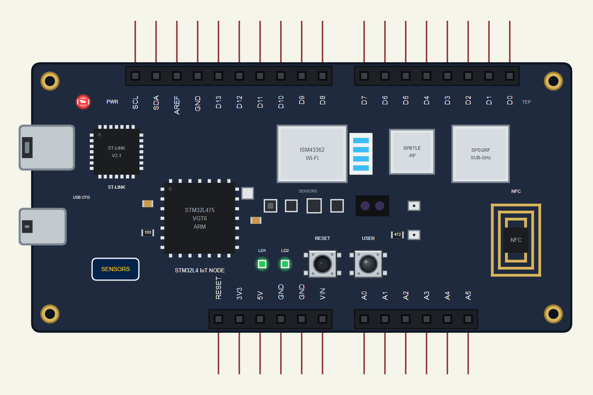
Search B-L475 in Pick Devices; the device is in TEPBL475.LIB (Microprocessor ICs, Bluetooth Boards), with the prefix U. The ST-LINK's USB opens the serial monitor, the SENSORS pad the Sensors window and a click on the Wi-Fi module the Wi-Fi panel.
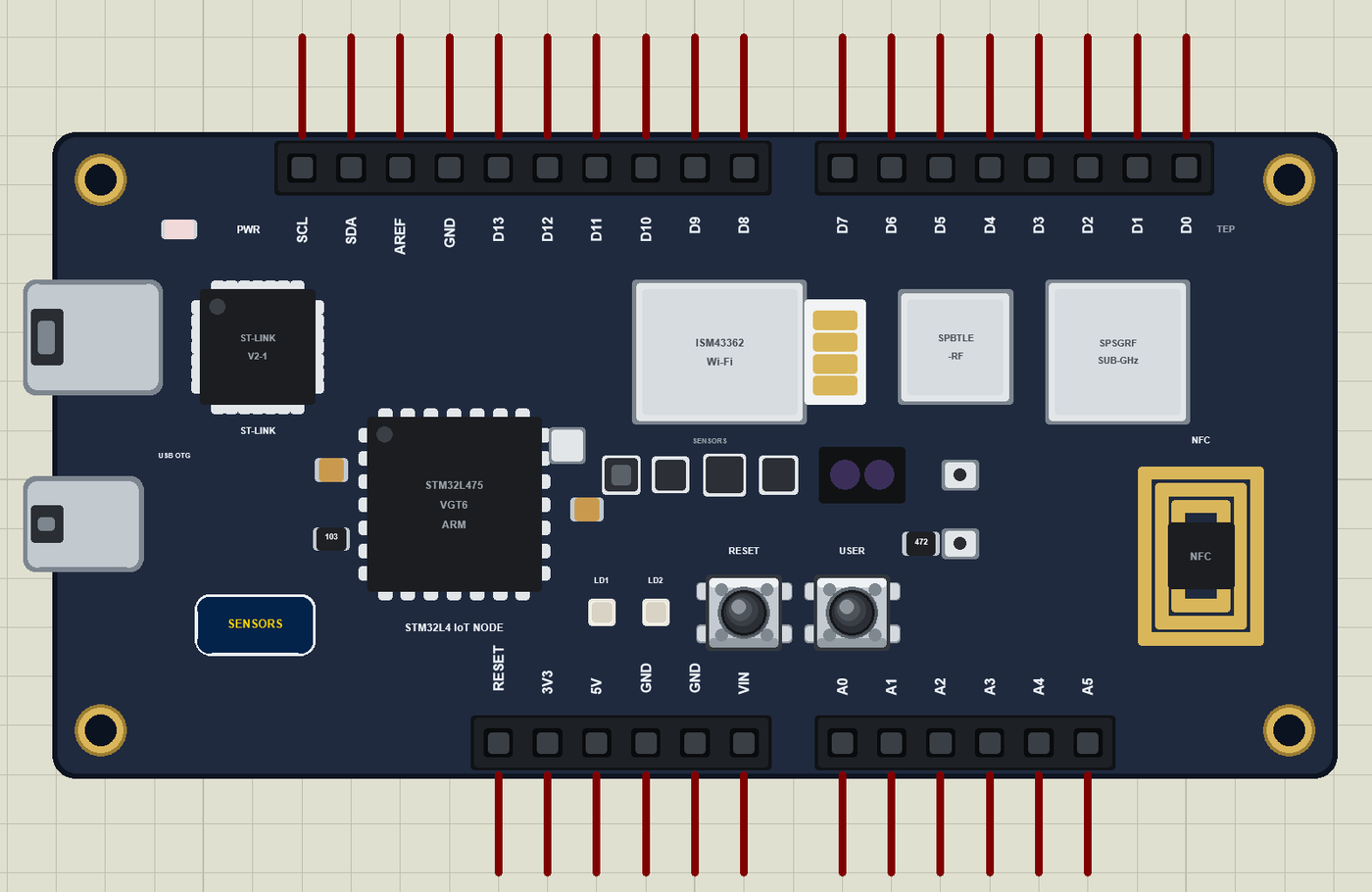
The Pins
| Pins | What the library does with them |
|---|---|
| D0 to D13 | GPIO, PWM with analogWrite, attachInterrupt; D0 / D1 Serial1; D10 to D13 SPI; D13 also drives LD1 |
| SDA, SCL | D14 and D15: Wire, the I2C bus |
| A0 to A5 | analogRead 0 to 1023 for 0 to 3.3 V, or GPIO |
| LED1, LED2 | LD1 (D13) and LD2, green, lit when HIGH |
| USER_BTN | the blue USER button, LOW when pressed |
| 3V3, 5V, GND, RESET | the supply and the reset |
The Sensors Window and the Wi-Fi Panel
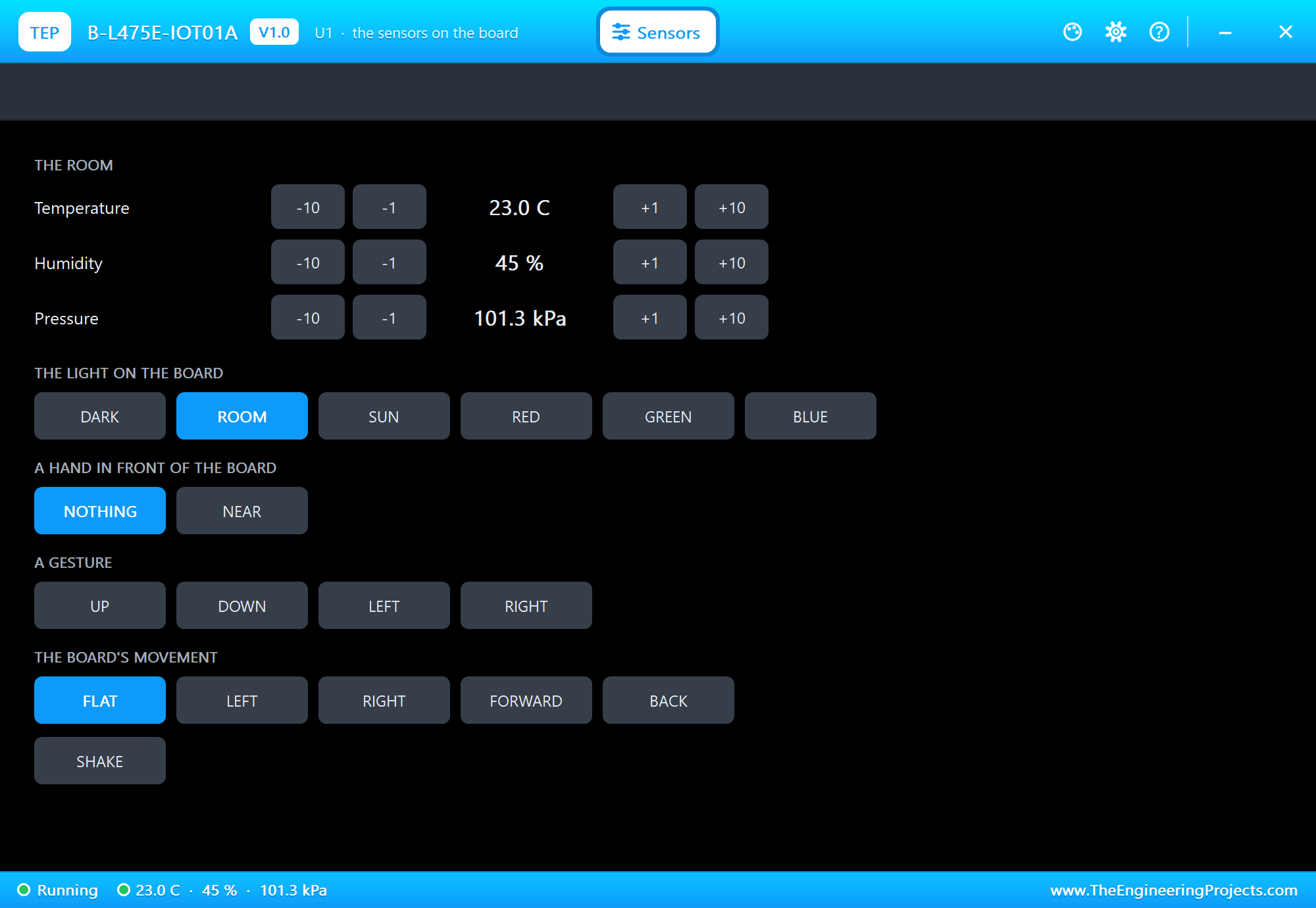
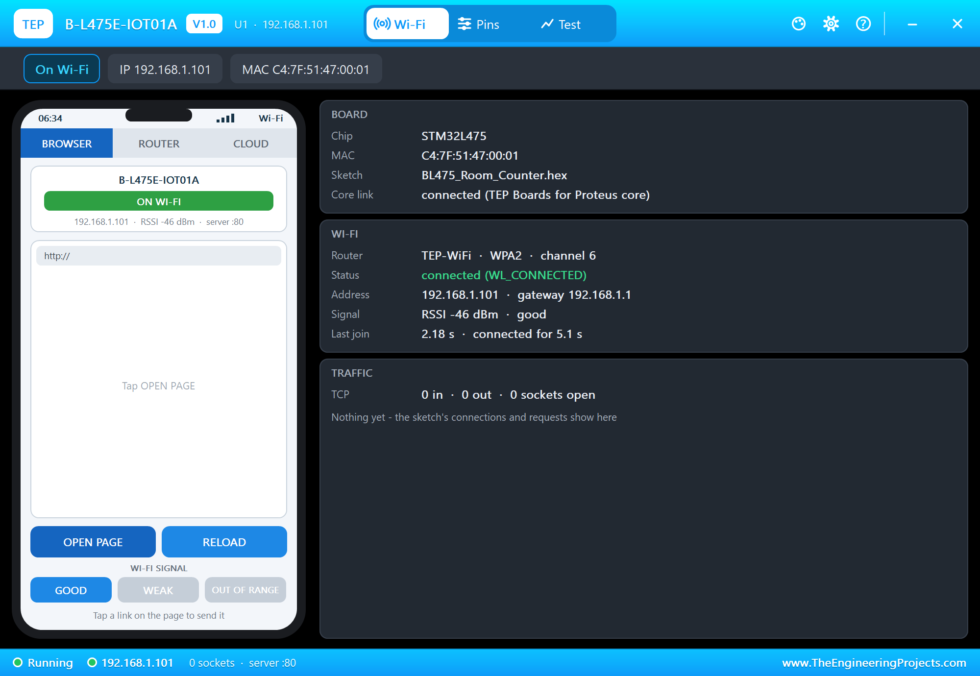
The SENSORS pad opens the Sensors window: the temperature, the humidity and the pressure with -10, -1, +1 and +10 buttons, a hand in front of the board, a gesture (UP, DOWN, LEFT, RIGHT), a tilt and a shake. A click on the ISM43362 module opens the Wi-Fi panel with the network, the address and the traffic.
Download B-L475E-IOT01A Library for Proteus
Click the button below to download B-L475E-IOT01A-Library-for-Proteus-v1.0.zip (about 3.3 MB, without the source code of the models):
B-L475E-IOT01A Library for Proteus V1.0- README.txt: installation, the demo, the pins, the properties, troubleshooting and the limits.
- Proteus Library Files:
TEPBL475.LIBand the phone and laptop:TEPMOBILE.LIBandTEPLAPTOP.LIB. - Proteus Model Files:
TEPNET.DLL. - Arduino Code: the demo sketch and the TEP Boards for Proteus add-on 1.69.0, with WiFi, WebServer, ArduinoBLE and the sensor libraries.
- Proteus Simulation: the demo project, its HEX file and a copy of the DLL.
No Proteus yet? Read How to Download and Install Proteus 7 and 8. New to libraries? Follow How to Install a New Library in Proteus.
How to Install B-L475E-IOT01A Library for Proteus
- Close Proteus and extract the whole zip file, for example to your Desktop.
- Copy the files from Proteus Library Files into the LIBRARY folder of Proteus.
- Copy
TEPNET.DLLfrom Proteus Model Files into the MODELS folder, replacing an older one. - Delete
TEPBL475.IDXfrom the LIBRARY folder if it is there. - For your own sketches, copy Arduino Code\TEP Boards for Proteus\hardware into your Arduino sketchbook (Documents\Arduino) and restart the Arduino IDE; the board is ST B-L475E-IOT01A IoT Node (TEP Proteus).
- Start Proteus, press P and search for B-L475.
Demo: a Wi-Fi Meeting Room Counter in Simulation
Offices waste a lot of time on rooms that are booked but empty, or empty-looking but full. A counter at the door knows how many people are inside right now, and a page on the office Wi-Fi lets everybody check before walking over. The same count can later run the lights and the ventilation, or feed a booking system. Unlike a camera, a distance sensor only sees that something passed, not who it was, so the count stays anonymous, which matters in offices, schools and hospitals.
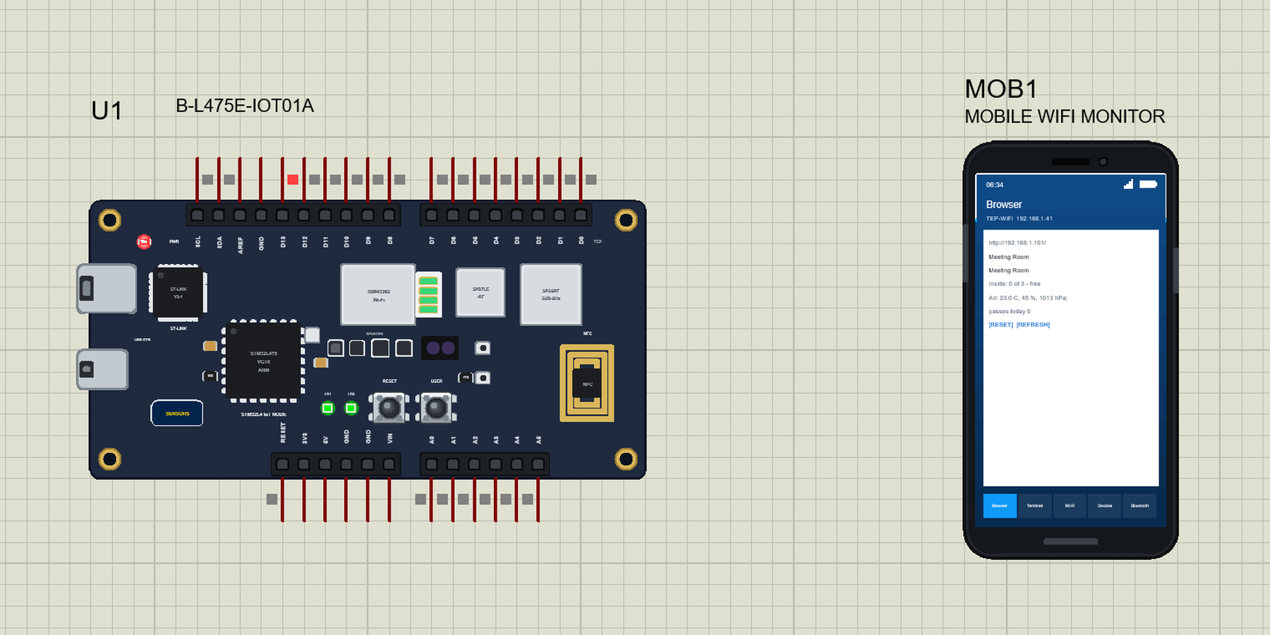
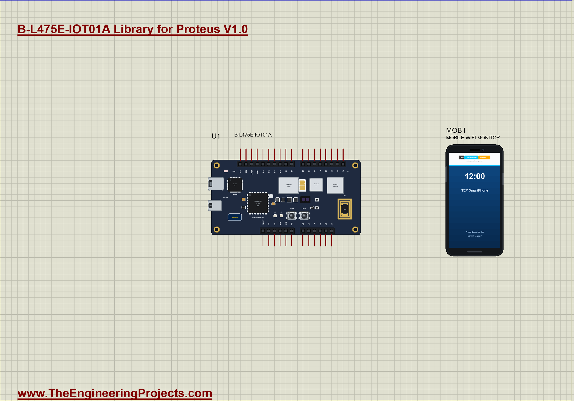
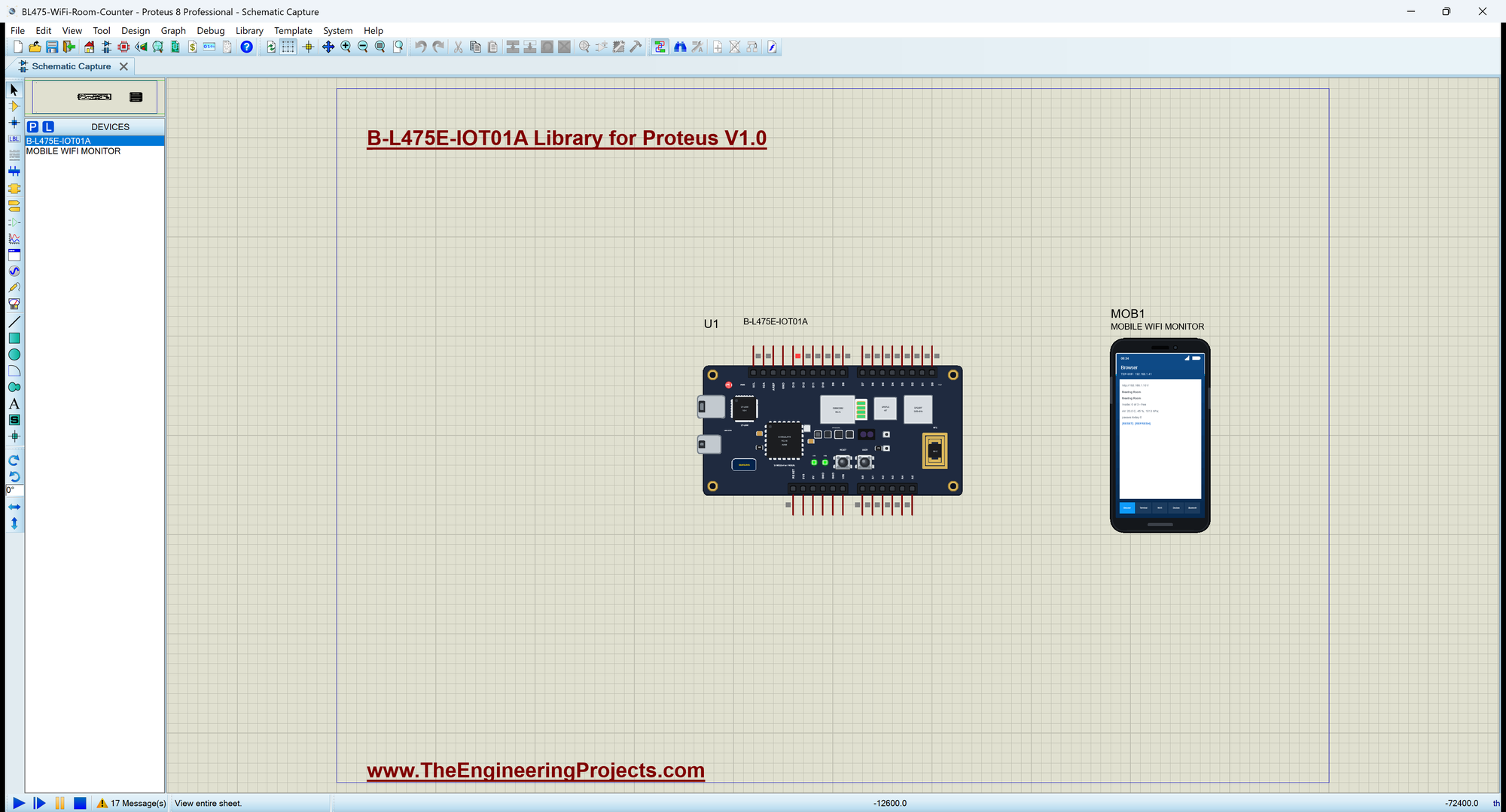
Open BL475-WiFi-Room-Counter.pdsprj. U1 runs BL475_Room_Counter.hex, and MOB1 is the phone, whose browser opens the board's page. There are no wires on this sheet. The serial monitor is the same window as our TEP Serial Monitor Advance for Proteus.
In or Out
The time-of-flight sensor at the door reports a pass as a gesture: to the RIGHT is someone walking in, to the LEFT someone walking out:
  if (APDS.gestureAvailable()) {
    const int g = APDS.readGesture();
    if (g == GESTURE_RIGHT) count(+1);
    else if (g == GESTURE_LEFT) count(-1);
  }
Counting
count() keeps the number of people inside, never lets it go below zero, counts every pass for the day and reports when the room becomes full or free:
void count(int change) {
  if (change < 0 && inside == 0) { Serial.println(F(">> LEFT, but the room is already empty")); return; }
  inside += change;
  passes++;
  Serial.print(change > 0 ? F(">> Someone came in: ") : F(">> Someone left: "));
  Serial.print(inside); Serial.print(F(" of ")); Serial.print(CAPACITY);
  Serial.println(inside >= CAPACITY ? F(" - the room is FULL") : inside == 0 ? F(" - the room is free") : F(""));
  showLeds();
}
The Two LEDs
LD1 shows that the room is in use, LD2 that it is full. On this board LD1 is on D13, the same pin as the SPI clock, so a sketch that uses SPI should not rely on it:
void showLeds() {
  digitalWrite(LED1, inside > 0 ? HIGH : LOW);              // LD1: in use
  digitalWrite(LED2, inside >= CAPACITY ? HIGH : LOW);      // LD2: full
}
The Web Page
handleRoot() builds the page with the people inside, the state, the air and the passes, and the links RESET and REFRESH:
void handleRoot() {
  String h = "<html><head><title>Meeting Room</title></head><body><h1>Meeting Room</h1>";
  h += "<p>Inside: <b>" + String(inside) + " of " + String(CAPACITY) + "</b> - " + String(inside >= CAPACITY ? "FULL" : inside > 0 ? "in use" : "free") + "</p>";
  h += "<p>Air: " + String(tempC, 1) + " C, " + String(humidity, 0) + " %, " + String(pressure, 0) + " hPa; passes today " + String(passes) + "</p>";
  h += "<p><a href=\"/reset\">RESET</a> <a href=\"/\">REFRESH</a></p></body></html>";
  server.send(200, "text/html", h);
}
Run the Simulation
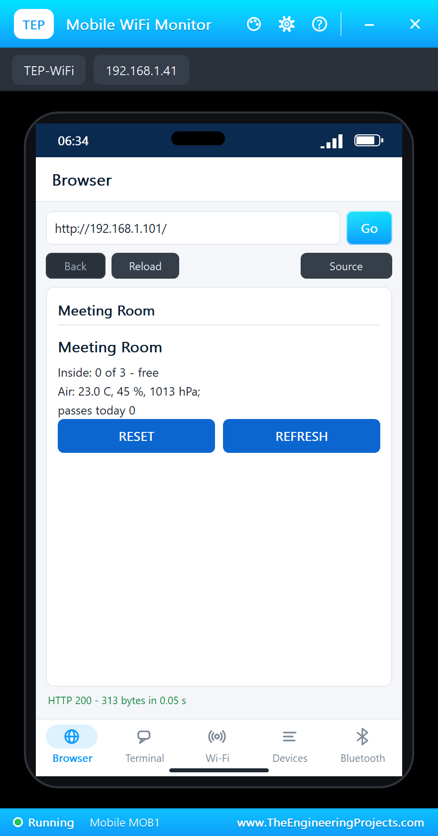
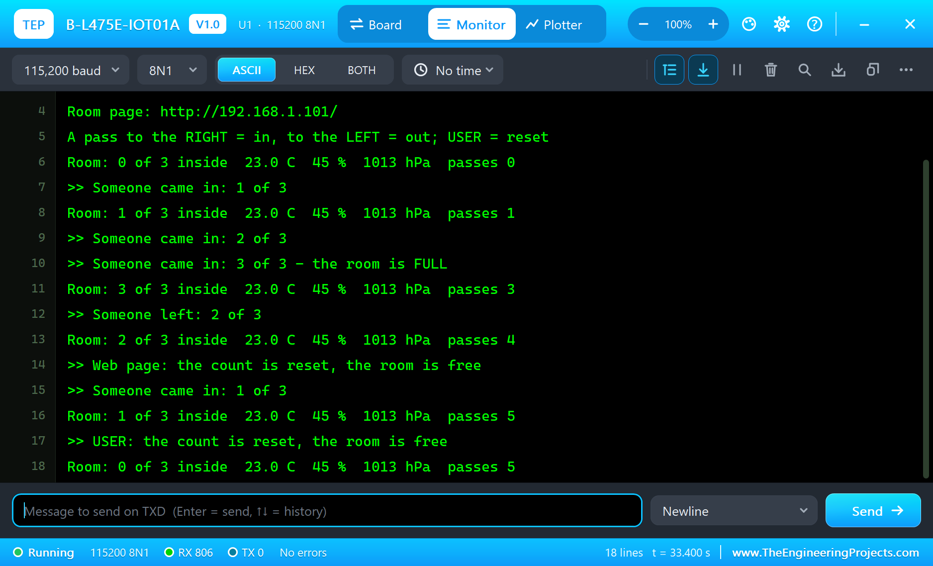
Press Run. The board joins TEP-WiFi and prints the address of its page. The room is empty:
B-L475E-IOT01A Wi-Fi Meeting Room Counter - The Engineering Projects
Connecting to TEP-WiFi
Wi-Fi connected, IP 192.168.1.101
Room page: http://192.168.1.101/
A pass to the RIGHT = in, to the LEFT = out; USER = reset
Room: 0 of 3 inside  23.0 C  45 %  1013 hPa  passes 0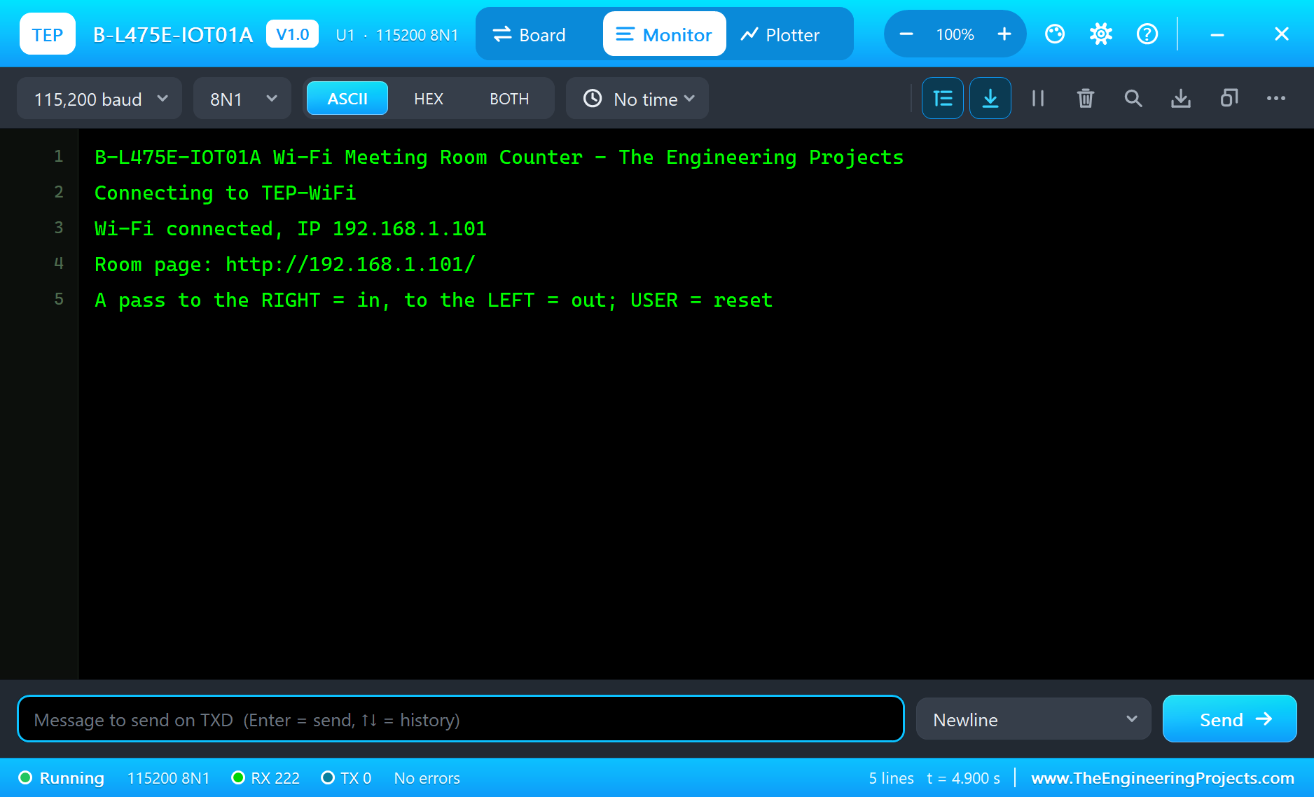
Open the Page
Click the phone and press Go: the browser opens http://192.168.1.101/ and shows the meeting room:
People Come In
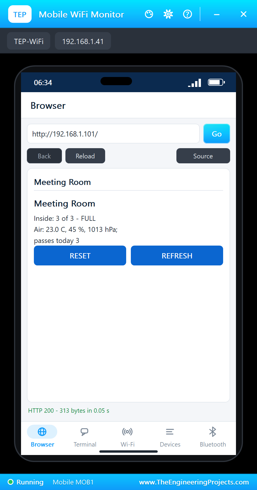
In the Sensors window click the gesture RIGHT: someone came in and LD1 lights. Two more, and the room is full: LD2 lights too, and the page says FULL after a Reload:
>> Someone came in: 1 of 3
Room: 1 of 3 inside  23.0 C  45 %  1013 hPa  passes 1
>> Someone came in: 2 of 3
>> Someone came in: 3 of 3 - the room is FULL
Room: 3 of 3 inside  23.0 C  45 %  1013 hPa  passes 3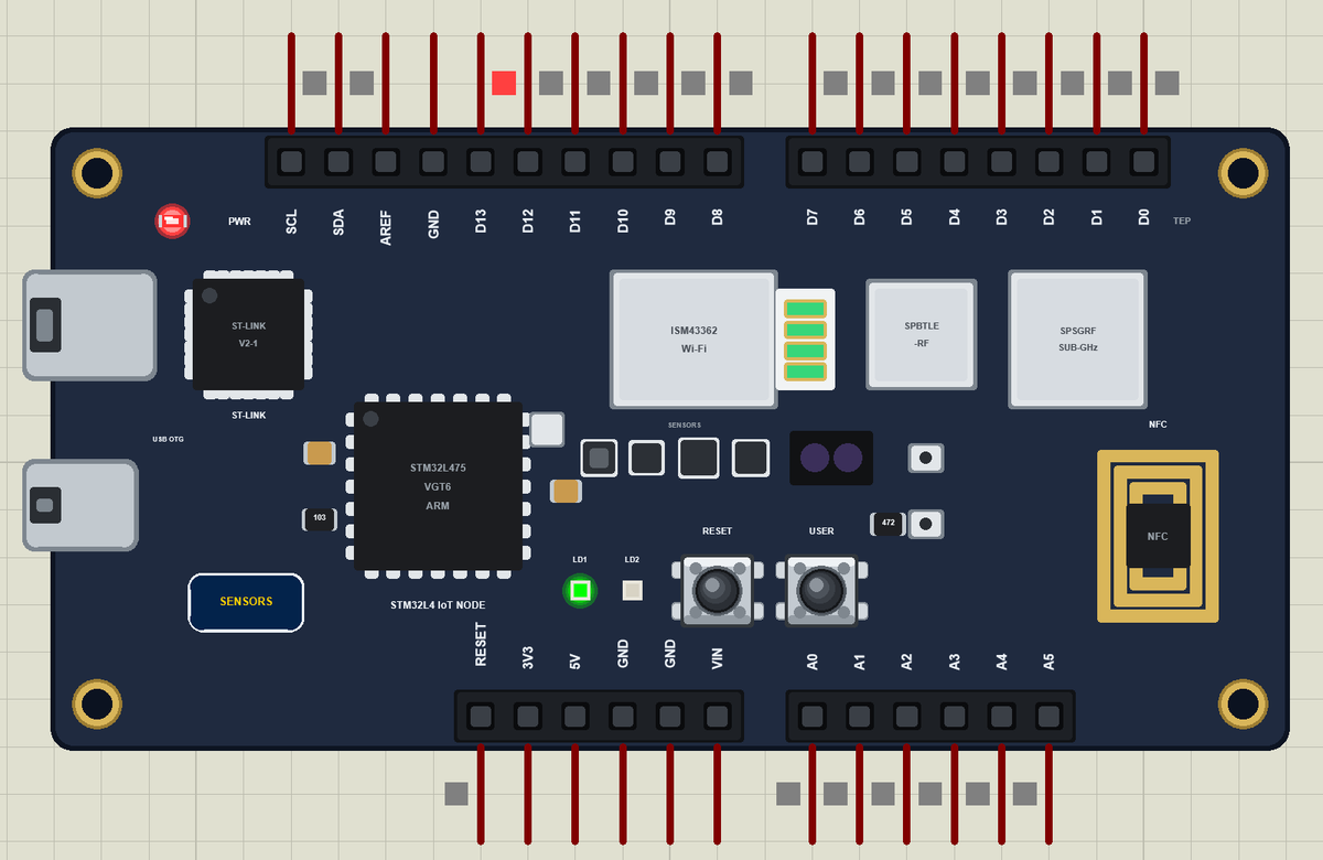
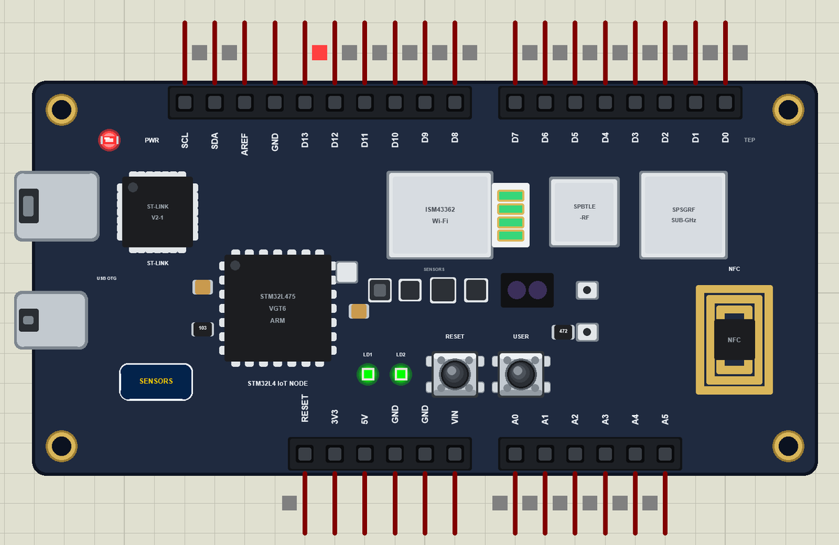
Here is the complete circuit while the simulation runs:
Someone Leaves
Click the gesture LEFT: one person left, the room is no longer full and LD2 goes out:
>> Someone left: 2 of 3
Room: 2 of 3 inside  23.0 C  45 %  1013 hPa  passes 4
Reset
Tap RESET on the page: the count goes back to zero and both LEDs go out. The USER button does the same on the board, for the cleaner at the end of the day. The passes are kept, so the page still shows how busy the room was today, which is the number a facility manager usually wants:
>> Web page: the count is reset, the room is free
>> Someone came in: 1 of 3
Room: 1 of 3 inside  23.0 C  45 %  1013 hPa  passes 5
>> USER: the count is reset, the room is free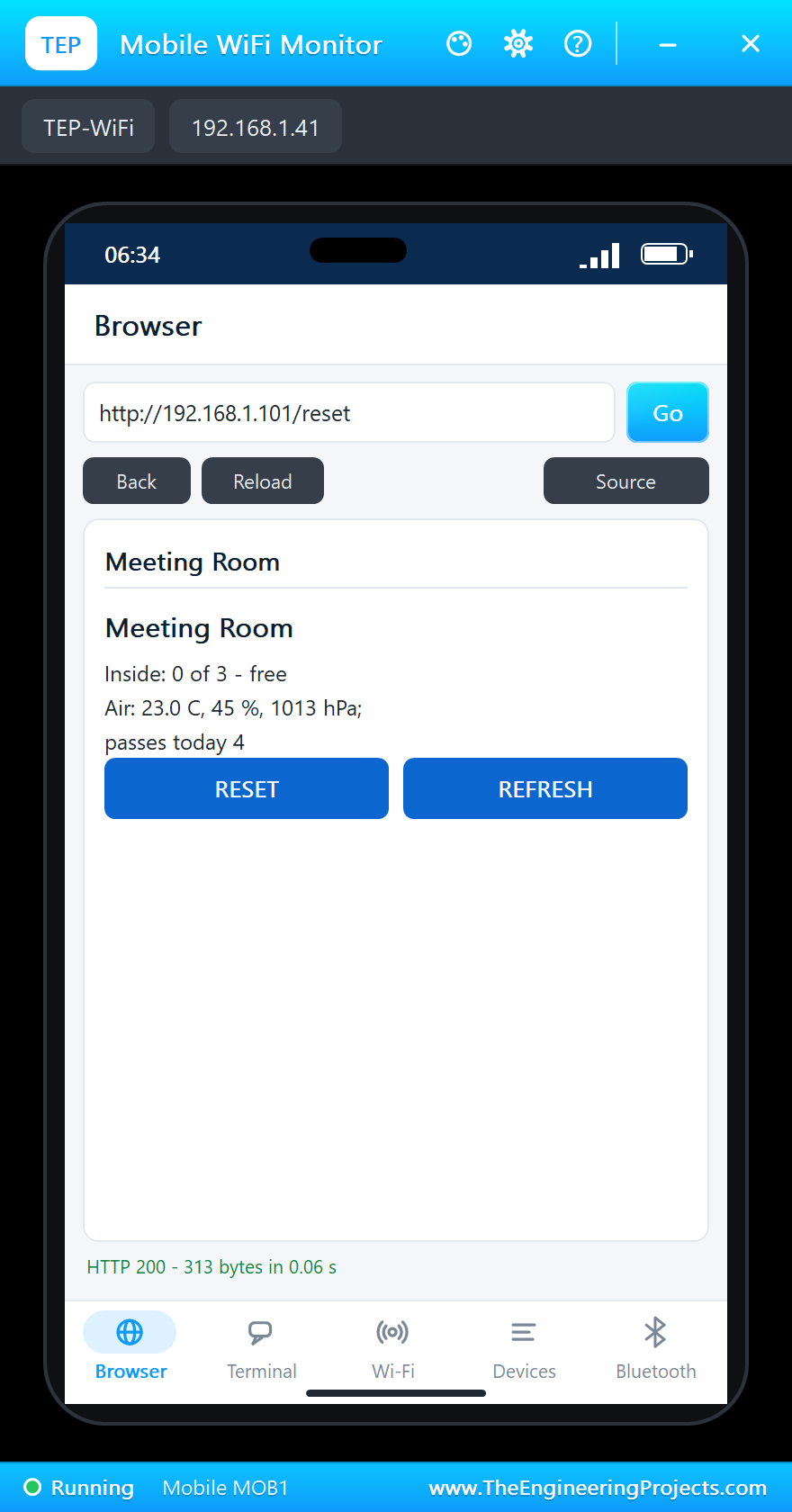
Try It Yourself
- Change
CAPACITYto 8 for a bigger room. - Make LD2 blink when the room is over capacity instead of just full.
- Add a
/historypage with the number of people every 15 minutes. - Use the pressure or the temperature to warn when a full room gets stuffy.
Ideas to Extend the Counter
- Advertise the count over Bluetooth LE for a door sign made with a second board.
- Send the count to a cloud platform so a whole floor of rooms shows on one dashboard.
- Switch the lights and the ventilation off when the room has been empty for ten minutes.
- Use the NFC tag so a phone tapped on the board opens the room's page.
Your Own Sketches
Write the sketch in the Arduino IDE with the board ST B-L475E-IOT01A IoT Node (TEP Proteus), use Sketch > Export Compiled Binary and set the part's PROGRAM property to the .hex. On a real board, the STM32duino core with its WiFiST, STM32duinoBLE and sensor libraries, or STM32CubeIDE with ST's packages, does the same work; the structure of your program, connect, sense, decide, serve, stays the same.
Things to Know Before Using a Real B-L475E-IOT01A
- 3.3 V logic: the Arduino headers are 3.3 V; check a 5 V shield before you plug it in.
- The Wi-Fi module speaks AT commands over SPI: use ST's WiFiST library, not a generic Wi-Fi library.
- 2.4 GHz Wi-Fi only: the ISM43362 is an 802.11 b/g/n module.
- LD1 shares D13: it blinks with the SPI clock when SPI is used.
- Privacy: a people counter should count, not identify; keep the data anonymous.
Properties of the B-L475E-IOT01A
| Property | What it does |
|---|---|
| PROGRAM | the sketch: a .hex from TEP Boards for Proteus (board "ST B-L475E-IOT01A IoT Node") |
| MONITOR, BAUD, AUTOOPEN | the built-in serial monitor: on, its baud rate (115200), open at Run |
| TEMPERATURE, HUMIDITY, PRESSURE | the room at Run (the demo: 23 C, 45 %, 101.3 kPa) |
Troubleshooting
- The board never connects: the network is TEP-WiFi with the password 12345678; wait for
WL_CONNECTED. - The phone shows no page: press Go or Reload after the monitor prints the page's address.
- No gestures arrive: call
APDS.begin()and readAPDS.gestureAvailable()in the loop. - LD1 flickers: it is on D13, the SPI clock.
- A number goes wrong above 32767: int is 16 bits in the simulation - use long.
Limitations of the Simulation
- Wi-Fi joins our simulated network: there is no real router, and the ISM43362's own protocol is not modelled. Bluetooth LE works as a peripheral only.
- The sub-GHz module, the NFC tag, the microphones, the Quad-SPI flash and USB OTG are drawn, not modelled.
- Your sketch gets 8 KB of RAM in the simulation, and int is 16 bits there.
- STM32 and ST are names of STMicroelectronics, ISM43362 of Inventek Systems, Arduino of Arduino, Wi-Fi of the Wi-Fi Alliance, and the Bluetooth word mark belongs to Bluetooth SIG; this library is not made or endorsed by them or by Labcenter.
- Tested in Proteus 8.5 in November 2026 (the demo as shipped, about 34 s of simulation). Proteus 7 is not supported.
So, that was all about the B-L475E-IOT01A Library for Proteus. I hope it helps you try your STM32 IoT ideas in a simulation before you buy the board - the network, the web page, the sensors, the LEDs and the buttons, all on one sheet. If you have any questions, ask in the comments and I will help you out. Till the next tutorial, take care and have fun!