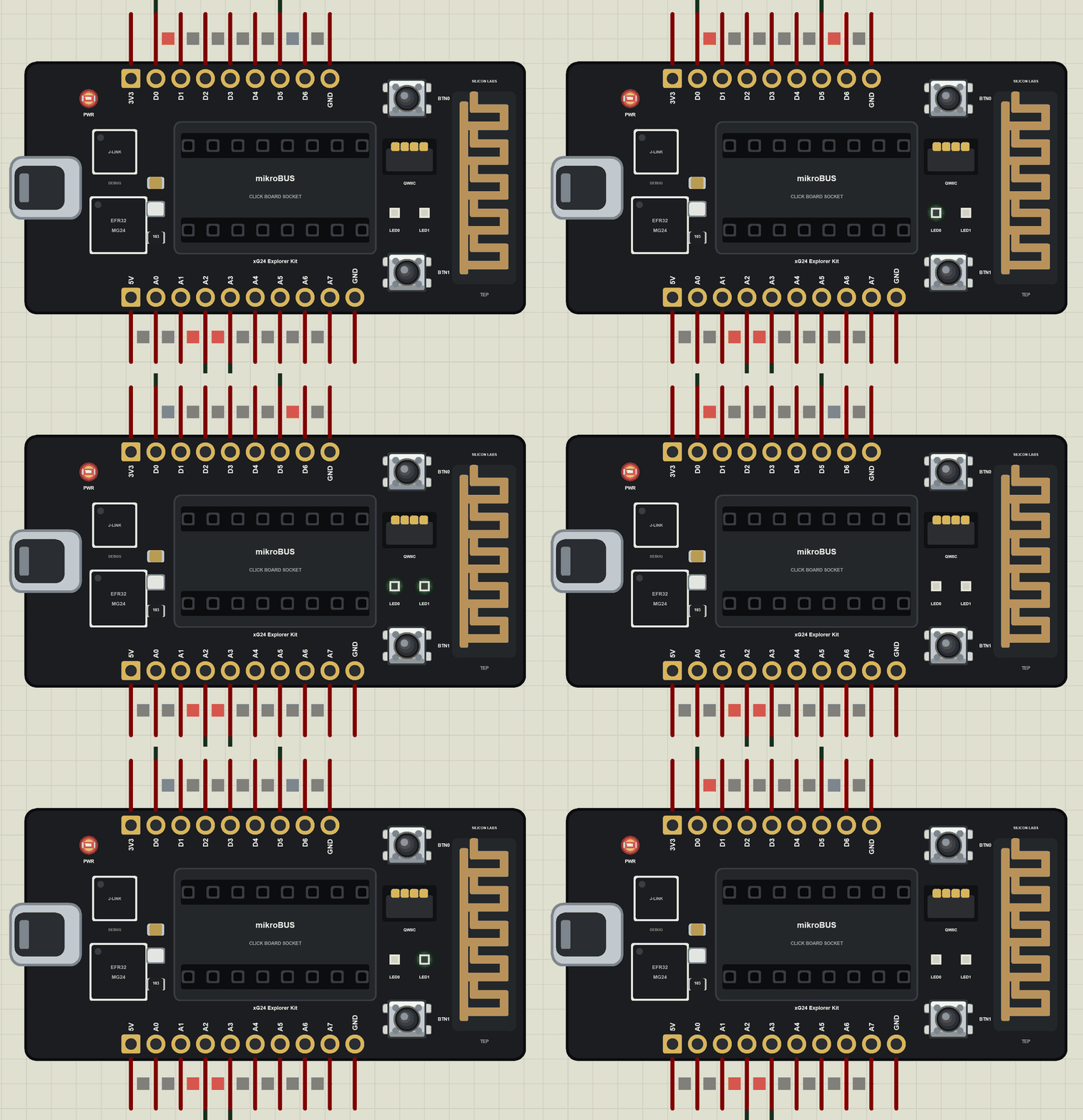
Hello friends, I hope you all are doing great. Today, I am going to share the xG24 Explorer Kit Library for Proteus, so you can run a Bluetooth LE simulation of Silicon Labs' EFR32xG24 Explorer Kit. This low-cost board carries the EFR32MG24 wireless chip, a mikroBUS socket for MikroElektronika click boards and a Qwiic connector, so it is made to be extended with sensors and actuators. With this library it runs your Arduino sketch in Proteus 8.5, talks Bluetooth LE to a phone, drives your own modules from its pads, and its two LEDs and two buttons work with a click.
xG24 Explorer Kit Library for Proteus
Latest version: V1.0 (November 2026, this tutorial)
Other new Arduino boards: UNO R4 WiFi · Nano ESP32 · UNO WiFi Rev2 · Nano 33 IoT · UNO Q · UNO R4 Minima · Nano Every · MKR WiFi 1010 · Nano RP2040 Connect · STM32 Black Pill · Nucleo-F401RE · STM32 Blue Pill · Teensy 4.1 · Arduino Due · Arduino Leonardo · Arduino Micro · BBC micro:bit V2 · GIGA R1 WiFi · MKR WAN 1310 · Nano 33 BLE Sense · XIAO nRF52840 Sense · RAK4631 WisBlock · Nano Matter · nRF52840 DK · nRF5340 DK · nRF9151 DK · nRF7002 DK · Nordic Thingy:53 · xG24 Dev Kit
RF modules: nRF24L01 · nRF24L01 PA LNA · CC1101 · RFM69HCW · HC-12 · 433MHz RF · XBee
Temperature and weather sensors: DHT11 / DHT22 · DS18B20 · BME280 · BMP280 · SHT31 · AHT20 · BME680 · MLX90614 · MAX6675
Helping Tools
- Laptop WiFi Monitor: a laptop on the Wi-Fi of your design: a browser, a TCP / UDP terminal and ping
- Mobile WiFi Monitor: a smartphone that opens the pages of your board and sends it commands
- Serial Monitor Advance: a serial terminal window for the UART of your board
For the demo we built a smart ventilation fan for a meeting room: a BME280 on the mikroBUS I2C pins measures the air, a motion sensor knows when people are in the room, and a relay runs the fan only when the room is occupied and stuffy. A phone follows everything over Bluetooth LE.
NOTICE: Proteus has no EFR32MG24 model, so our team has put a lot of effort into building this board ourselves: the pins, the LEDs, the buttons and Bluetooth LE are all our own model, and your sketch compiles with our free TEP Boards for Proteus add-on. Your feedback is the fuel that keeps us going, so please tell us what you think in the comments below. And if our free libraries help you, you can buy us a coffee. So, let's get started with the xG24 Explorer Kit Library for Proteus:
What is the xG24 Explorer Kit?
The EFR32xG24 Explorer Kit (xG24-EK2703A) is the low-cost little brother of the xG24 Dev Kit. It has the same EFR32MG24 wireless SoC, an Arm Cortex-M33 with 1536 kB of flash, 256 kB of RAM, a 2.4 GHz radio for Bluetooth LE and 802.15.4 and an AI/ML accelerator, and the same on-board J-Link debugger with a USB port and a virtual COM port. Instead of on-board sensors it has sockets: a mikroBUS socket that takes any of the hundreds of MikroElektronika click boards, and a Qwiic connector for SparkFun's and Adafruit's plug-in I2C boards. Two LEDs, two push buttons and a printed antenna complete the board.
| Part | The real xG24 Explorer Kit | In the library |
|---|---|---|
| SoC | EFR32MG24: Arm Cortex-M33, Bluetooth LE, Thread, Zigbee, Matter | your Arduino sketch, ArduinoBLE |
| mikroBUS socket | SPI, I2C, UART, analog, PWM and interrupt pins for a click board | drawn; its signals are on the pads |
| Qwiic connector | a second I2C bus with a 4-pin plug | drawn; wire Qwiic parts to A2 and A3 |
| On the board | LED0, LED1, BTN0, BTN1, J-Link with USB | all of them, animated; the USB opens the monitor |
| Memory | 1536 kB flash, 256 kB RAM | about 256 KB of flash, 8 KB of RAM |
What Is mikroBUS?
mikroBUS is an open socket standard from MikroElektronika: two rows of eight pins that carry SPI, I2C, UART, an analog input, a PWM output, an interrupt line, a reset line and both 3.3 V and 5 V. Every click board uses the same pinout, so a temperature sensor, a GPS receiver, a motor driver or an LTE modem plugs into the same socket without a single wire. For a research team this means a new sensor can be tried in minutes. In the simulation the socket is drawn, and its signals come out on the pads: I2C on A2 and A3, SPI on D1 to D4 and the UART on A4 and A5.
What Is Qwiic?
Qwiic is SparkFun's plug-in system for I2C: a small 4-pin JST-SH connector with 3.3 V, ground, SDA and SCL, and boards that carry two of these connectors so they can be chained one after another. Adafruit's STEMMA QT uses the same connector, so hundreds of sensors, displays and inputs plug in without soldering and without any chance of swapping the wires. On the real Explorer Kit the Qwiic port has its own I2C bus (Wire1), separate from the mikroBUS. In the simulation, wire a Qwiic-style sensor to A2 and A3, as the demo does with its BME280.
Why Ventilate on Demand?
Ventilation is one of the biggest energy users in offices and schools, and a large part of it runs in empty rooms. Demand-controlled ventilation measures what the room needs: whether people are there, and how warm, humid or stale the air is. A motion sensor and a temperature and humidity sensor are the cheapest way to start, and a CO2 sensor is the usual next step. The same logic, made into a small wireless node like our demo, can be added to an existing building without new cables or a new control system.
Explorer Kit or Dev Kit?
Silicon Labs makes two small xG24 boards. The Dev Kit carries its own sensors (temperature, humidity, pressure, light, motion, microphones), which makes it ideal for edge AI work without any extra hardware; see our xG24 Dev Kit Library for Proteus. The Explorer Kit leaves the sensors out and gives you sockets instead, so you choose exactly the parts your project needs. Both run the same sketches with the pin names of the Silicon Labs Arduino core.
Where Is It Used?
Universities use the Explorer Kit in wireless and embedded courses because one board and a box of click boards cover many lab exercises. Product teams use it to try a sensor or an actuator quickly before they design their own board, and to build Matter and Thread prototypes on the same chip that goes into the product. Smart-building projects such as occupancy-based ventilation, lighting and room booking are a typical fit.
A simulation lets you build and test the whole logic of such a device before any hardware arrives: the sensor readings, the decisions, the relay, the LEDs, the buttons and the Bluetooth service. When it works in the Proteus simulation, the move to the real kit is much quicker.
How Bluetooth LE Notifications Work
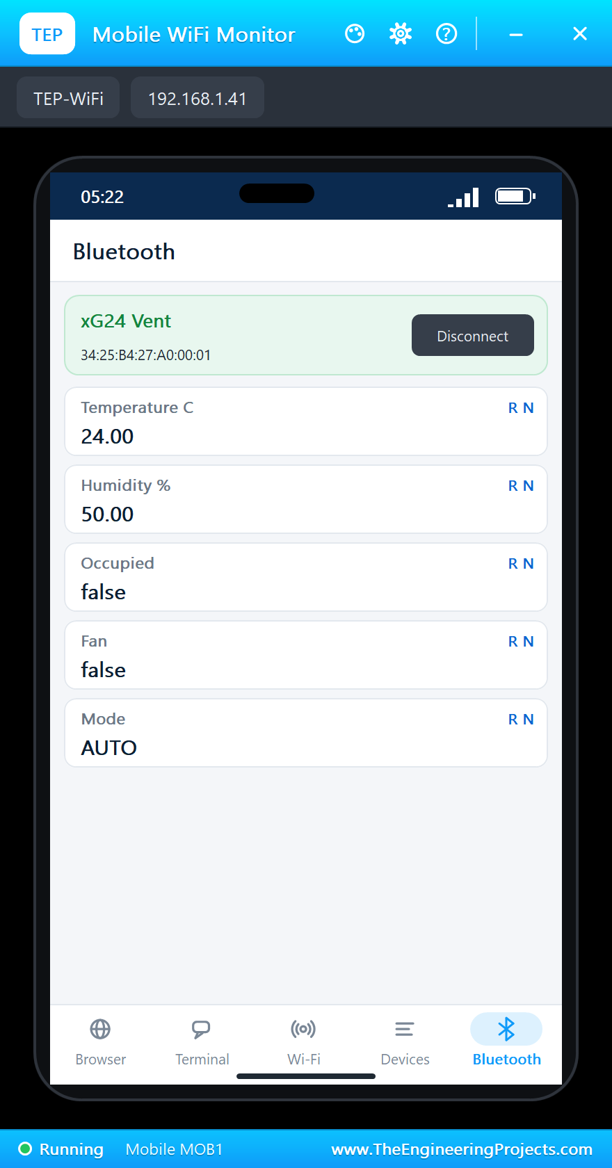
A Bluetooth LE device offers services, and each service holds characteristics, small values with a UUID that a phone can read. Our fan has one service with five characteristics: the temperature, the humidity, the room occupied, the fan on and the mode. A phone subscribes once, and the board sends a notification every time a value changes. Our Mobile WiFi Monitor is that phone in Proteus.
Features of the xG24 Explorer Kit Library for Proteus
- The board as it looks: the black PCB with the USB-C port, the J-Link debugger, the EFR32MG24, the mikroBUS socket, the Qwiic connector, LED0, LED1, BTN0, BTN1, the printed antenna and the breakout pads, drawn compact, with our small TEP signature.
- Your sketch: a .hex for "Silicon Labs xG24 Explorer Kit (TEP Proteus)" with the Silicon Labs Arduino core's pin names: D0 to D6, A0 to A7, LED0, LED1, BTN0 and BTN1.
- The pads: digital I/O, PWM, analogRead, interrupts, Wire, SPI and Serial1 for your own modules.
- Bluetooth LE: ArduinoBLE, with our phone as the central: scan, connect, read, write and notifications.
- Real LEDs and buttons: the LEDs light when HIGH, as on the real kit; the buttons are clicked on the board.
- A complete package: about 4.6 MB with the part, the add-on, the BME280, PIR, relay and phone libraries and the demo, without the source code of the models.
The xG24 Explorer Kit in Proteus Simulation
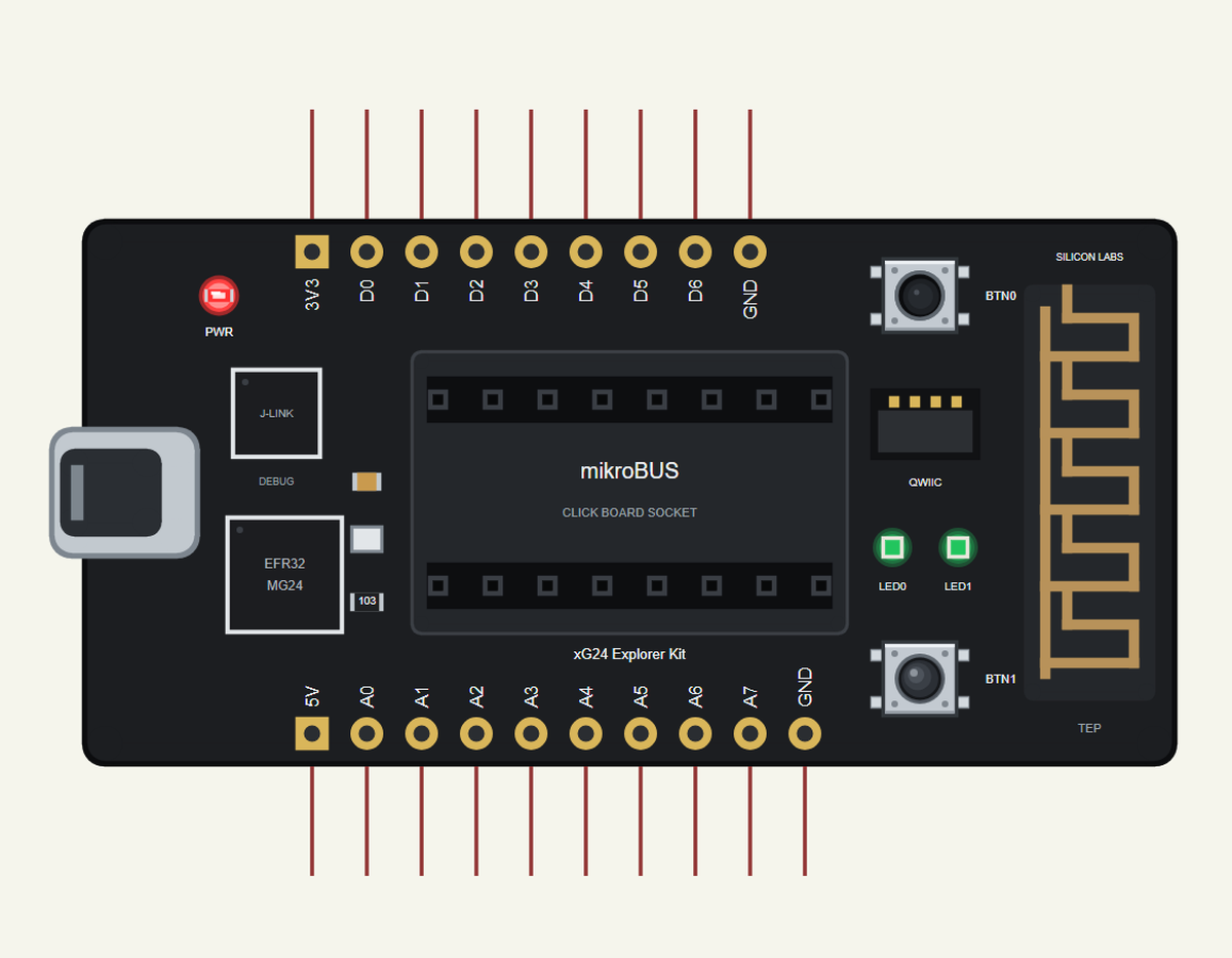
Search XG24 in Pick Devices; the device is in TEPXG24EK.LIB (Microprocessor ICs, Bluetooth Boards), with the prefix U. Click the USB-C port for the serial monitor.
The Pins
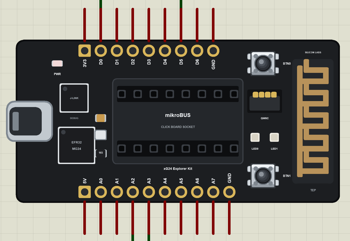
| Pins | What the library does with them |
|---|---|
| D0 to D6 | GPIO, PWM with analogWrite, attachInterrupt; D1 MOSI, D2 MISO, D3 SCK, D4 SS |
| A0, A1, A6, A7 | analogRead 0 to 1023 for 0 to 3.3 V, or GPIO |
| A2, A3 | SDA and SCL: Wire, the mikroBUS I2C |
| A4, A5 | Serial1 TX and RX: the mikroBUS UART |
| LED0, LED1 | the LEDs (15, 16), lit when HIGH |
| BTN0, BTN1 | the buttons (17, 18), LOW when pressed |
| 3V3, 5V, GND | the supply |
Download xG24 Explorer Kit Library for Proteus
Click the button below to download xG24-Explorer-Kit-Library-for-Proteus-v1.0.zip (about 4.6 MB, without the source code of the models):
xG24 Explorer Kit Library for Proteus V1.0- README.txt: installation, the demo, the pins, the properties, troubleshooting and the limits.
- Proteus Library Files:
TEPXG24EK.LIBand the demo's parts:TEPBME280.LIB,TEPHCSR501.LIB,TEPRELAY.LIB,TEPMOBILE.LIBandTEPLAPTOP.LIB. - Proteus Model Files:
TEPNET.DLL,TEPBME280.DLL,TEPHCSR501.DLLandTEPRELAY.DLL. - Arduino Code: the demo sketch and the TEP Boards for Proteus add-on 1.66.0, with ArduinoBLE.
- Proteus Simulation: the demo project, its HEX file and copies of the DLLs.
No Proteus yet? Read How to Download and Install Proteus 7 and 8. New to libraries? Follow How to Install a New Library in Proteus.
How to Install xG24 Explorer Kit Library for Proteus
- Close Proteus and extract the whole zip file, for example to your Desktop.
- Copy the files from Proteus Library Files into the LIBRARY folder of Proteus.
- Copy the DLLs from Proteus Model Files into the MODELS folder, replacing an older TEPNET.DLL.
- Delete
TEPXG24EK.IDXfrom the LIBRARY folder if it is there. - For your own sketches, copy Arduino Code\TEP Boards for Proteus\hardware into your Arduino sketchbook (Documents\Arduino) and restart the Arduino IDE; the board is Silicon Labs xG24 Explorer Kit (TEP Proteus). Install Adafruit BME280 Library and Adafruit Unified Sensor from the Library Manager.
- Start Proteus, press P and search for XG24.
Demo: a Smart Ventilation Fan in Simulation
Many buildings run their ventilation on a timer, all day, whether a room is full or empty. A fan that runs only when people are in the room and the air is warm or humid saves energy and noise. Ours combines three ready-made parts with the Explorer Kit and a phone.
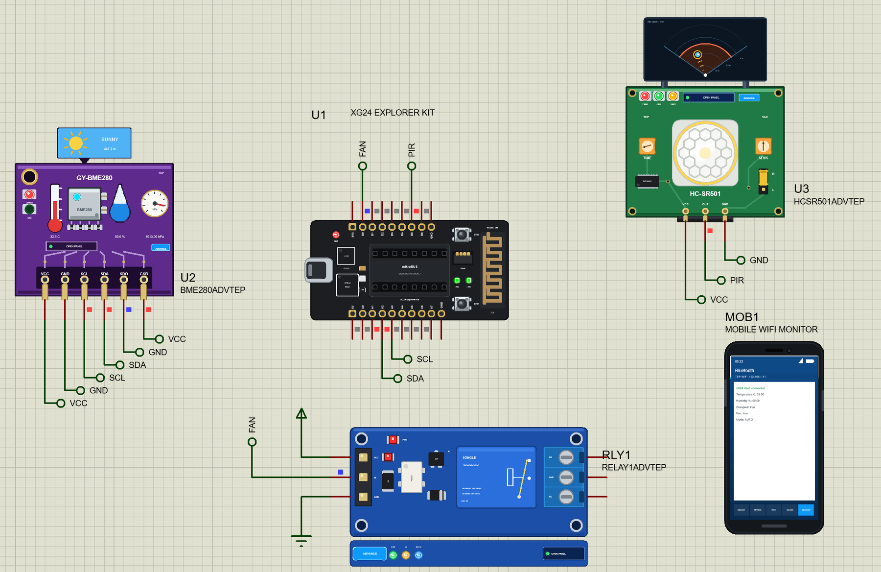
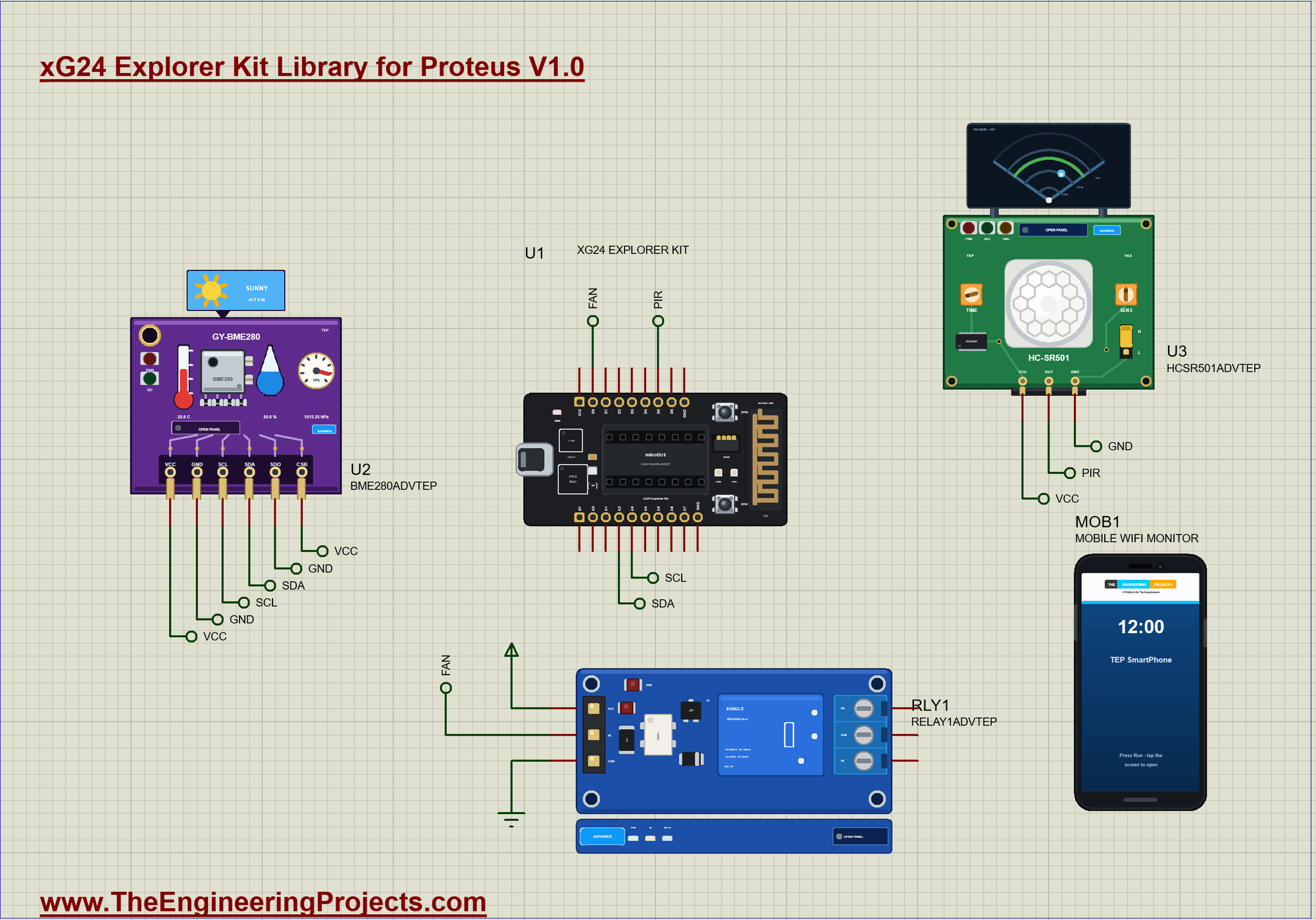
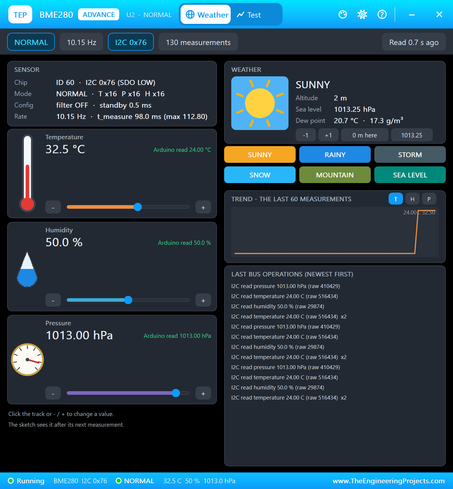
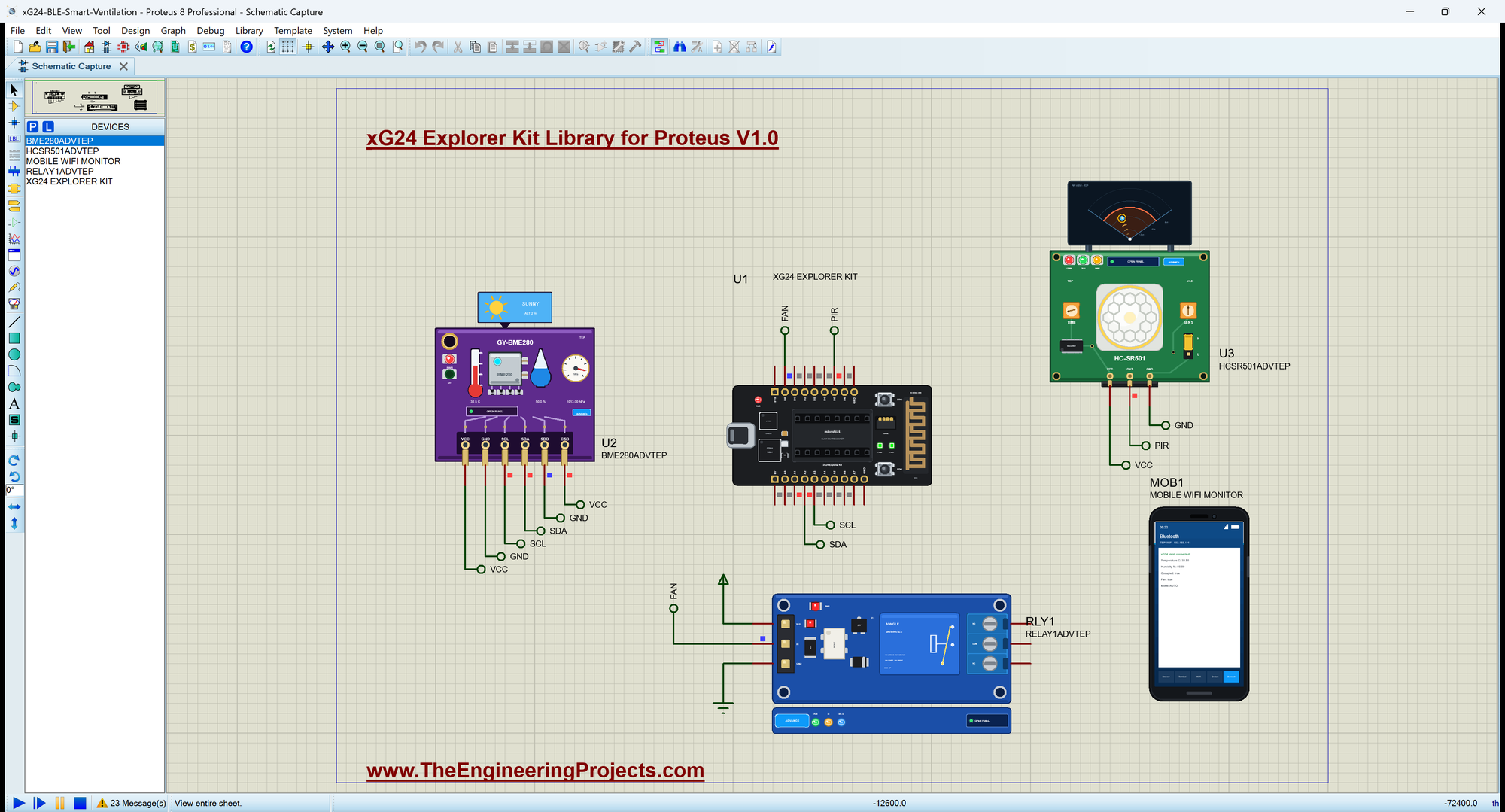
Open xG24-BLE-Smart-Ventilation.pdsprj. U1 runs xG24_Smart_Ventilation.hex. U2 is the BME280 from our BME280 Sensor Library, U3 the HC-SR501 motion sensor and RLY1 the fan's relay from our Relay Module Library, all three in the Advance version. MOB1 is the phone. The serial monitor is the same window as our TEP Serial Monitor Advance for Proteus.
The Wiring
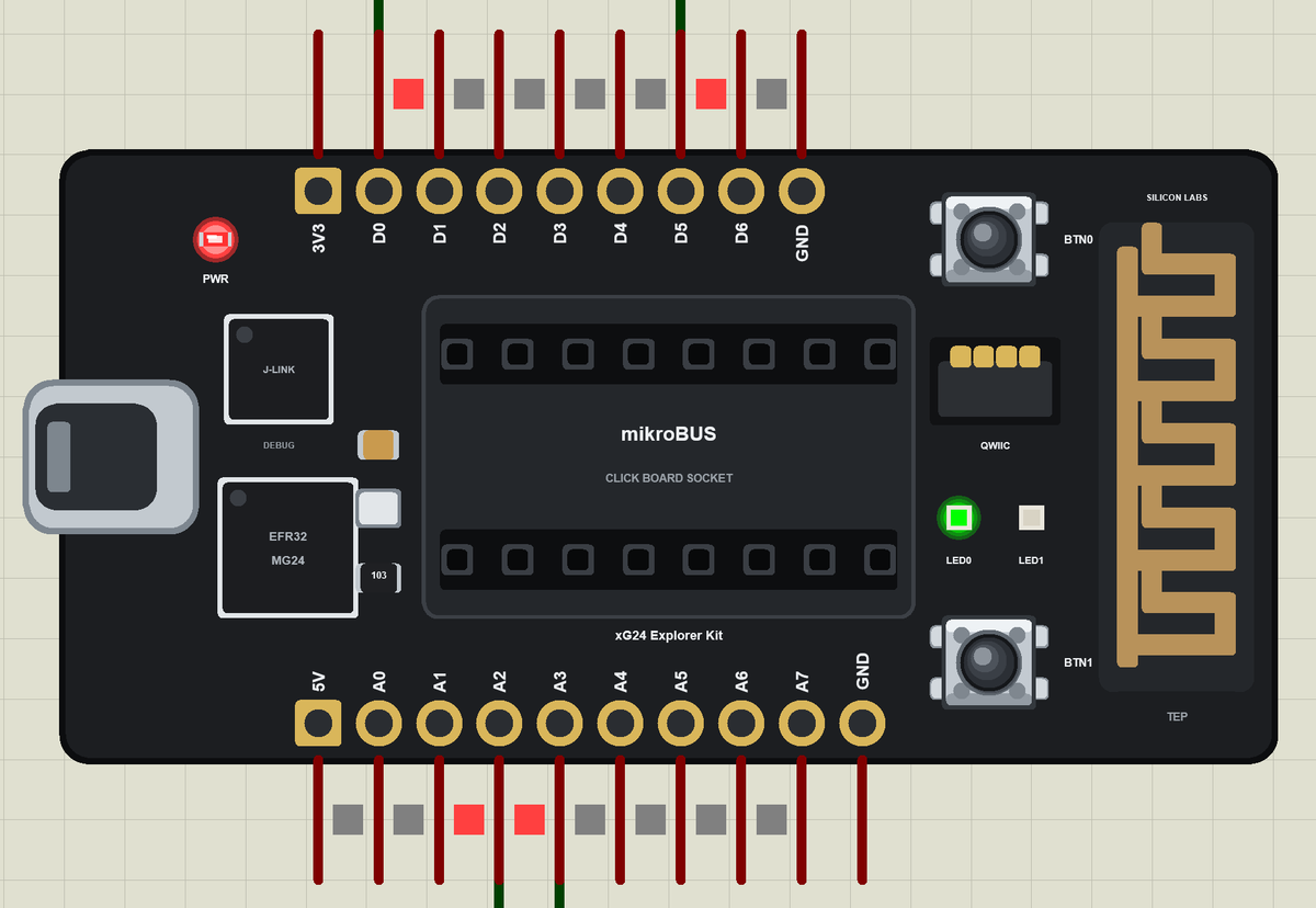
The BME280's SDA and SCL go to A2 and A3, the mikroBUS I2C pins, and its SDO pin goes to GND, which selects the address 0x76. The motion sensor's OUT is on D5 through the label PIR, and the relay's IN on D0 through the label FAN. The relay module switches on when its input is LOW, so the sketch writes HIGH to the pin before it makes it an output.
Occupied or Empty
A PIR sensor only reports movement, and people sitting in a meeting hardly move. So the sketch keeps the room OCCUPIED for 8 s after the last movement (a real room would use a few minutes), and only then calls it EMPTY:
void watchMotion() {
  if (digitalRead(PIR_PIN) == HIGH) {
    lastMotion = millis();
    if (!occupied) {
      occupied = true;
      digitalWrite(LED0, HIGH);
      occupiedChar.writeValue(true);
      Serial.println(F(">> Motion: room OCCUPIED"));
      decide();
    }
  } else if (occupied && millis() - lastMotion > HOLD_MS) {
    occupied = false;
    digitalWrite(LED0, LOW);
    occupiedChar.writeValue(false);
    Serial.println(F(">> No motion for 8 s: room EMPTY"));
    decide();
  }
}
The Decision
decide() runs every second. A boost from BTN0 wins over everything; the OFF mode keeps the fan off; in AUTO the fan runs only when the room is occupied and warm (above 26 C) or humid (above 65 %):
void decide() {
  if (boostUntil && millis() < boostUntil) { setFan(true, F("boost")); return; }
  if (boostUntil) { boostUntil = 0; Serial.println(F(">> Boost over")); }
  if (!autoMode) { setFan(false, F("mode OFF")); return; }
  const bool stuffy = tempC > WARM_C || humidity > HUMID_RH;
  if (occupied && stuffy) setFan(true, tempC > WARM_C ? F("warm and occupied") : F("humid and occupied"));
  else if (!occupied) setFan(false, F("room empty"));
  else setFan(false, F("room comfortable"));
}
The Fan
setFan() does nothing when the state does not change, so the relay never chatters; it drives the relay, LED1 and the Bluetooth characteristic together, and prints the reason:
void setFan(bool on, const __FlashStringHelper *why) {
  if (on == fan) return;
  fan = on;
  digitalWrite(FAN_PIN, on ? LOW : HIGH);                   // the relay module switches on when its IN is LOW
  digitalWrite(LED1, on ? HIGH : LOW);
  fanChar.writeValue(fan);
  Serial.print(on ? F(">> Fan ON (") : F(">> Fan OFF (")); Serial.print(why); Serial.println(F(")"));
}
The Bluetooth Service
The service holds the five values, each with BLERead | BLENotify; the temperature and the humidity use the standard UUIDs 0x2A6E and 0x2A6F:
BLEService ventService("19B10060-E8F2-537E-4F6C-D104768A1214");
BLEFloatCharacteristic tempChar("2A6E", BLERead | BLENotify);
BLEFloatCharacteristic humChar("2A6F", BLERead | BLENotify);
BLEBoolCharacteristic occupiedChar("19B10061-E8F2-537E-4F6C-D104768A1214", BLERead | BLENotify);
BLEBoolCharacteristic fanChar("19B10062-E8F2-537E-4F6C-D104768A1214", BLERead | BLENotify);
BLEStringCharacteristic modeChar("19B10063-E8F2-537E-4F6C-D104768A1214", BLERead | BLENotify, 8);
Run the Simulation
Press Run. The board starts advertising as "xG24 Vent". The room is at 24 C and 50 % and nobody is there, so the fan stays off:
xG24 Explorer Kit Bluetooth Smart Ventilation - The Engineering Projects
Advertising as "xG24 Vent", address 34:25:B4:27:A0:00:01
BTN0 = boost 20 s, BTN1 = mode AUTO / OFF
Room: 24.0 C  50 %  1013.0 hPa  empty  fan OFF  auto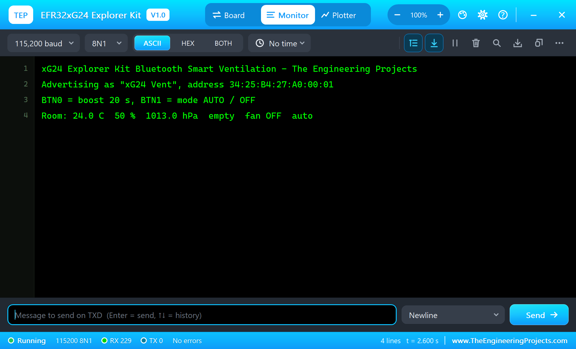
Connect the Phone
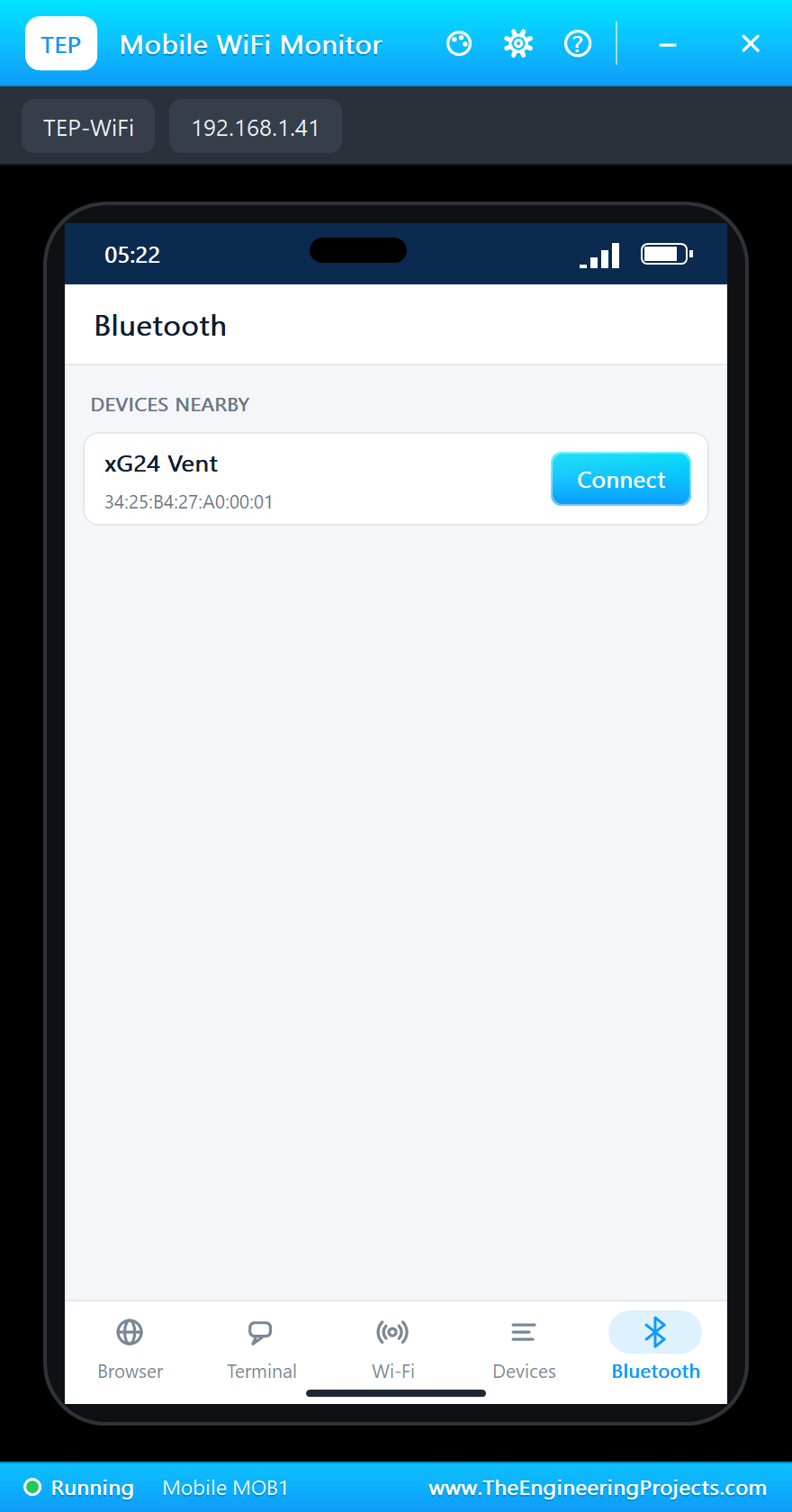
Click the phone, open its Bluetooth app, press SCAN and then Connect to "xG24 Vent":
People Come In
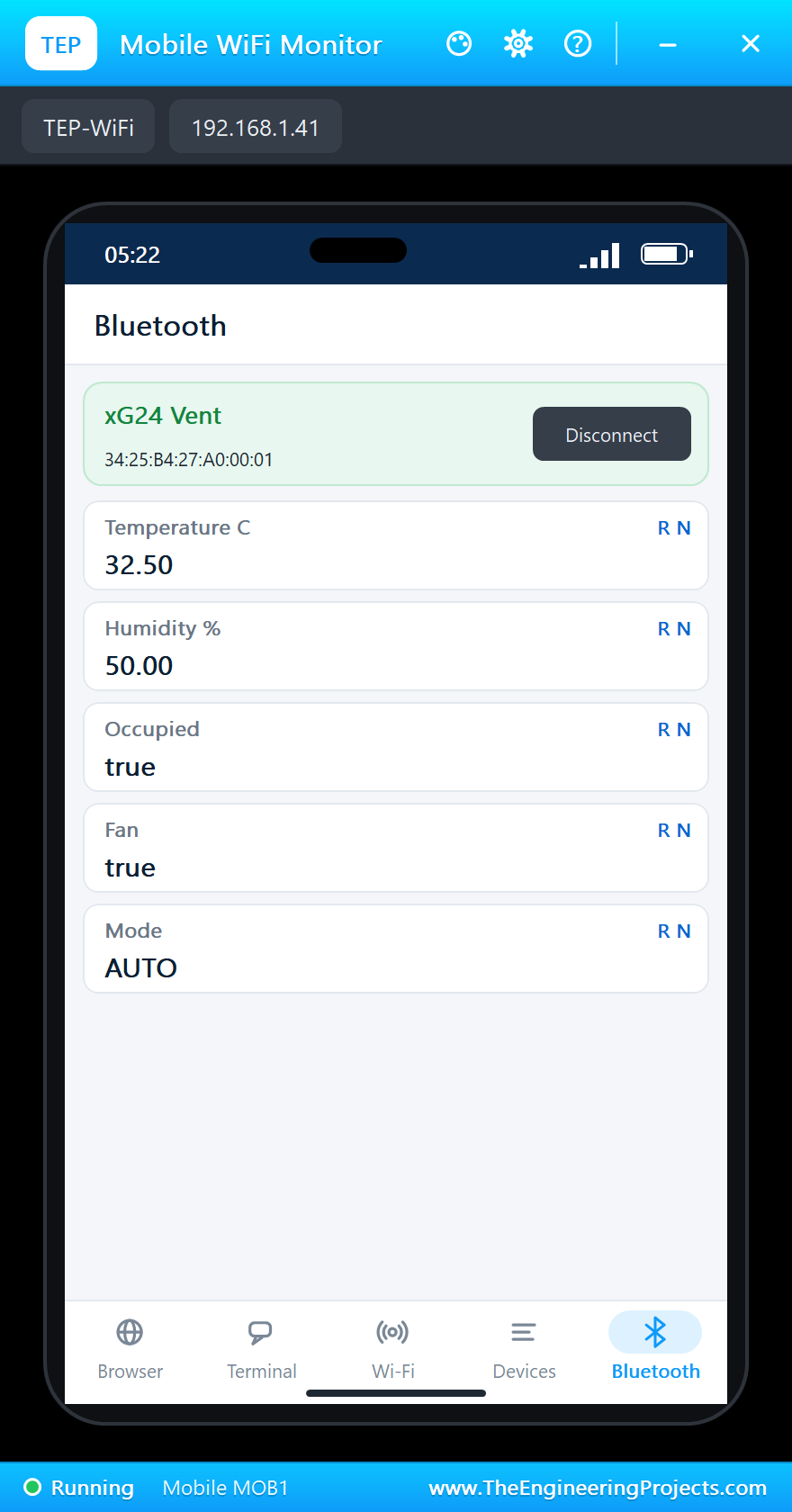
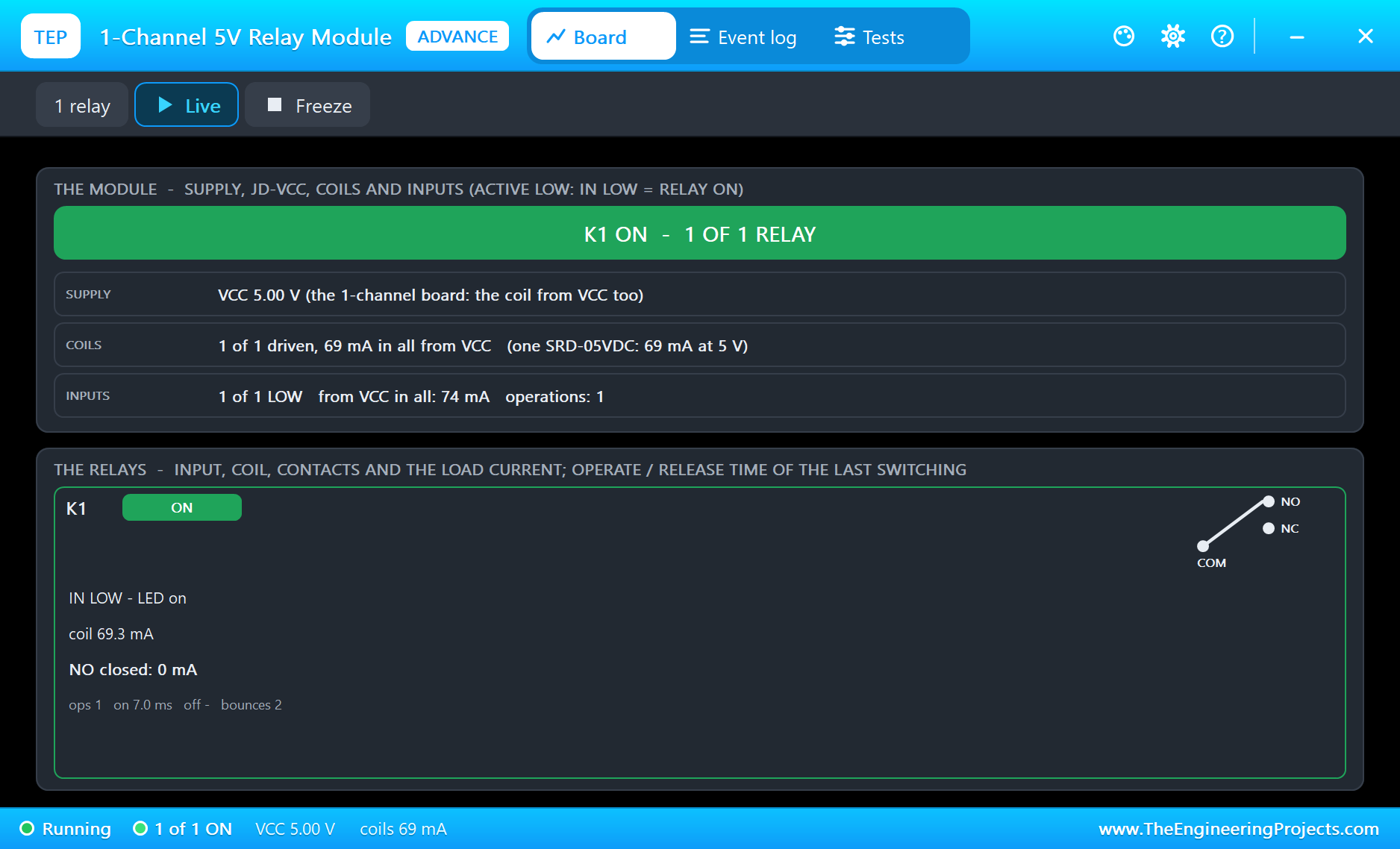
On the HC-SR501's pop-up make a movement: the room is OCCUPIED and LED0 lights. The air is still comfortable, so the fan stays off. Then make the room warm on the BME280's pop-up: warm and occupied, so the fan starts, with LED1 and the relay:
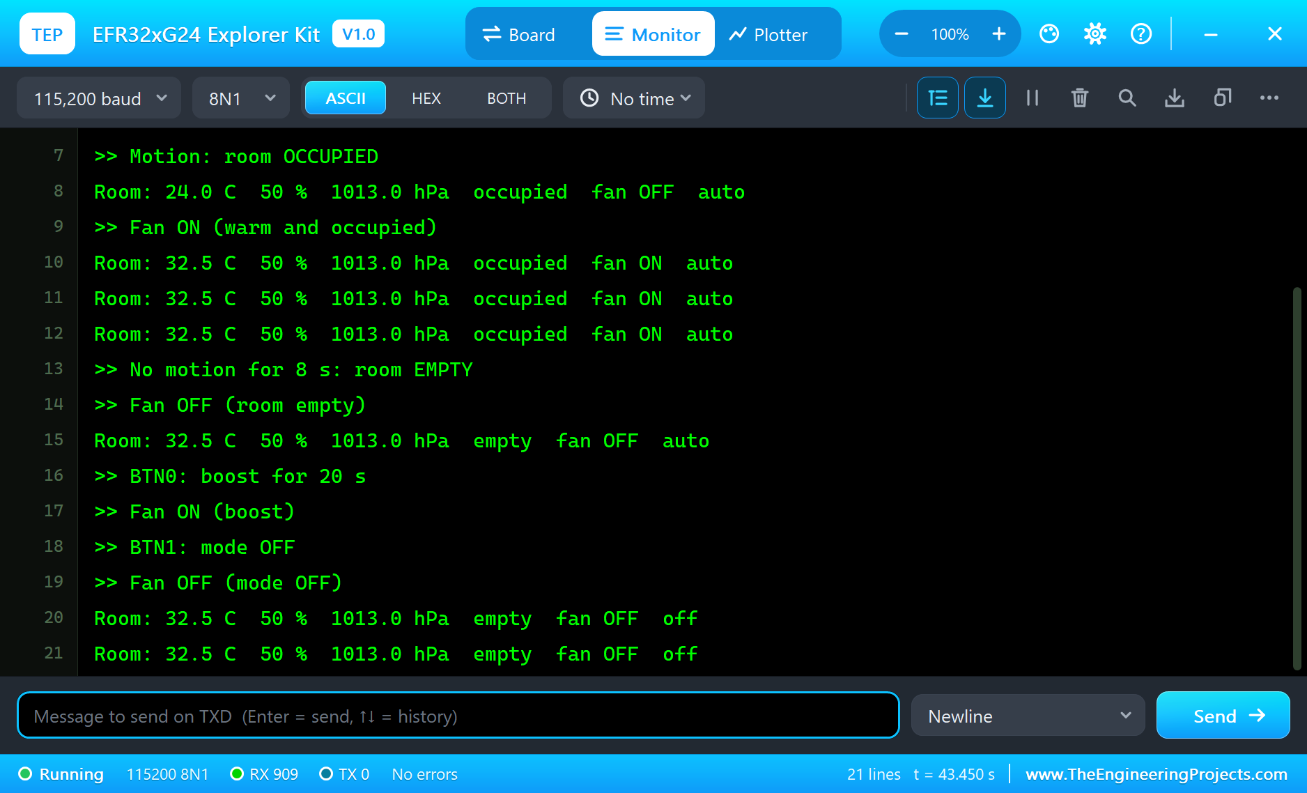
>> Motion: room OCCUPIED
Room: 24.0 C  50 %  1013.0 hPa  occupied  fan OFF  auto
>> Fan ON (warm and occupied)
Room: 32.5 C  50 %  1013.0 hPa  occupied  fan ON  auto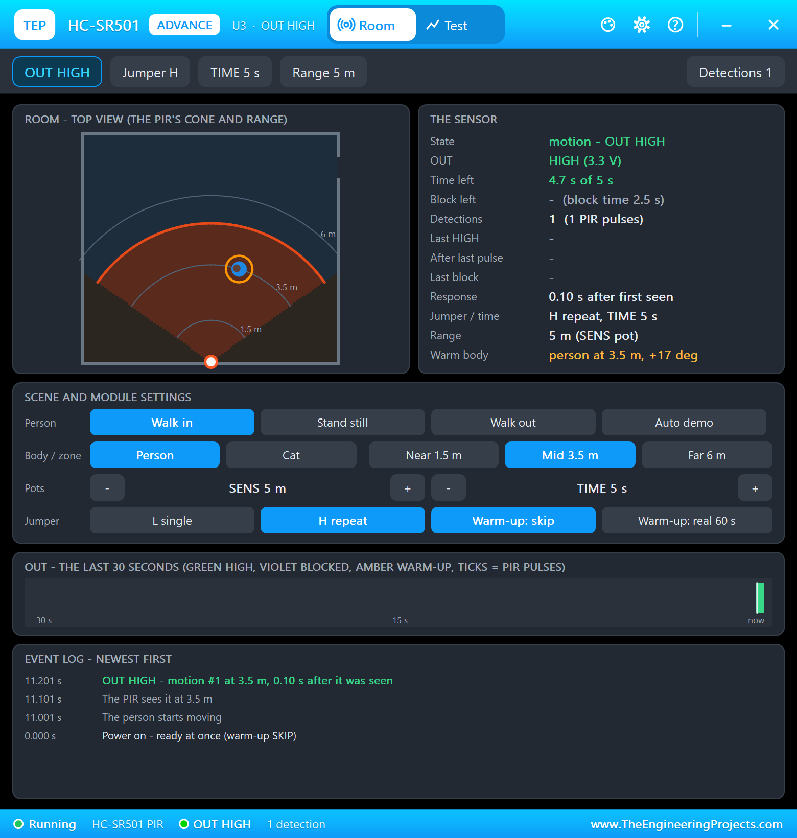
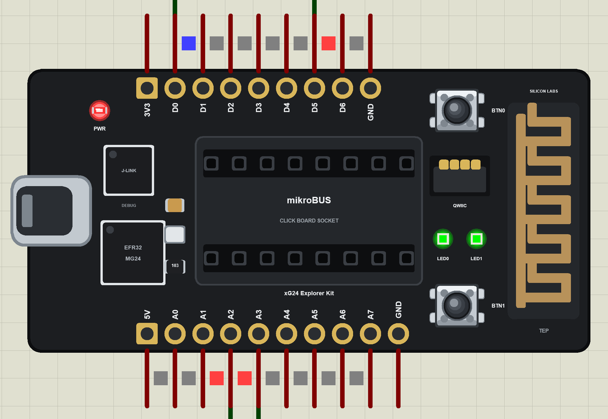
Here is the complete circuit while the simulation runs:
Everybody Leaves
Click Walk out on the HC-SR501's pop-up. The sensor's output drops after its 5 s time, and 8 s later the room is EMPTY: LED0 goes out and the fan stops, even though the room is still warm:
>> No motion for 8 s: room EMPTY
>> Fan OFF (room empty)
Room: 32.5 C  50 %  1013.0 hPa  empty  fan OFF  auto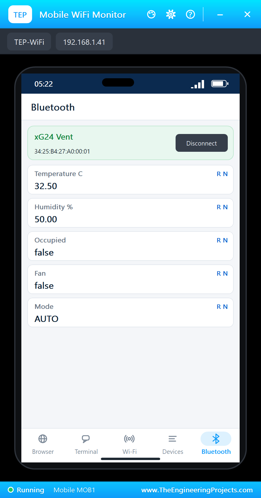
Boost and Off
Press BTN0 for a 20-second boost: the fan runs whatever the room. BTN1 switches the mode to OFF, which also ends the boost:
>> BTN0: boost for 20 s
>> Fan ON (boost)
>> BTN1: mode OFF
>> Fan OFF (mode OFF)
Room: 32.5 C  50 %  1013.0 hPa  empty  fan OFF  off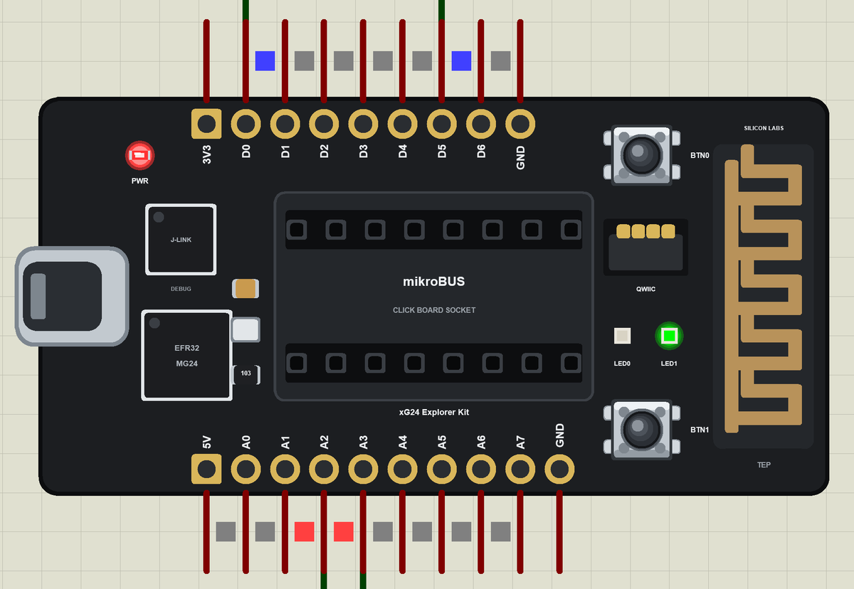
Try It Yourself
- Change
HOLD_MSto 5 minutes for a real room, and make LED0 blink in the last minute before the room counts as empty. - Add a CO2 click board on the mikroBUS I2C and run the fan on the CO2 level as well.
- Use PWM on D0 with a MOSFET instead of the relay, so the fan runs faster when the room is warmer.
- Add a writable characteristic so the phone can start a boost.
Ideas to Extend the Fan
- Count the people in the room with two motion sensors at the door.
- Log the occupancy per hour and send it to the phone, for a room-booking report.
- Connect several rooms over Thread and let one gateway show the whole floor.
- Turn the lights off with a second relay when the room is empty.
Your Own Sketches
Write the sketch in the Arduino IDE with the board Silicon Labs xG24 Explorer Kit (TEP Proteus), use Sketch > Export Compiled Binary and set the part's PROGRAM property to the .hex. The pin names are the ones of the Silicon Labs Arduino core, so the same sketch structure works on the real kit with a click board in its mikroBUS socket.
Things to Know Before Using a Real xG24 Explorer Kit
- 3.3 V logic: the pads and the mikroBUS signals are 3.3 V; a 5 V module needs a level shifter.
- Two I2C buses: on the real kit the mikroBUS uses Wire and the Qwiic connector uses Wire1.
- Click board pinouts: check which mikroBUS pins a click board really uses before you write the sketch.
- Mains needs care: a relay that switches a real fan carries dangerous voltage, so use a safe enclosure.
- The radio needs room: keep the printed antenna away from metal.
Properties of the xG24 Explorer Kit
| Property | What it does |
|---|---|
| PROGRAM | the sketch: a .hex from TEP Boards for Proteus (board "Silicon Labs xG24 Explorer Kit") |
| MONITOR, BAUD, AUTOOPEN | the built-in serial monitor: on, its baud rate (115200), open at Run |
Troubleshooting
- The phone finds nothing: press SCAN after "Advertising as" is printed; the sketch must call
BLE.advertise(). - "BME280 not found": the sensor is at 0x76 with SDO on GND, on A2 (SDA) and A3 (SCL).
- The fan acts backwards: the relay module switches on when IN is LOW.
- The LEDs look inverted: on this kit they light when the pin is HIGH.
- A number goes wrong above 32767: int is 16 bits in the simulation - use long.
Limitations of the Simulation
- Bluetooth LE works as a peripheral only. Thread, Zigbee and Matter are not modelled.
- The mikroBUS socket and the Qwiic connector are drawn: their signals are the pads, and the Qwiic port's own I2C bus is not modelled.
- Your sketch gets 8 KB of RAM in the simulation, and int is 16 bits there.
- EFR32, xG24 and Silicon Labs are names of Silicon Laboratories Inc., mikroBUS of MikroElektronika, Qwiic of SparkFun, Arduino of Arduino, and the Bluetooth word mark belongs to Bluetooth SIG; this library is not made or endorsed by them or by Labcenter.
- Tested in Proteus 8.5 in November 2026 (the demo as shipped, about 44 s of simulation). Proteus 7 is not supported.
So, that was all about the xG24 Explorer Kit Library for Proteus. I hope it helps you try your Bluetooth ideas with your own modules in a simulation before you buy the kit - the sensors, the relay, the LEDs, the buttons and the phone, all on one sheet. If you have any questions, ask in the comments and I will help you out. Till the next tutorial, take care and have fun!