Hello friends! This page collects our MATLAB projects into a learning path, from basic scripts to signal processing, image processing, hardware communication and Simulink models. You can use it to choose a project that matches both your current skills and the engineering question you want to explore. MATLAB is a broad numerical environment, so there is no need to learn every toolbox before starting. Begin with a small input, a clear calculation and an output you can check. Then extend the project only after you understand why the first result is correct. The original project links remain organized below. Some tutorials and downloads were created with older releases, so we will also discuss compatibility, toolbox requirements and how to evaluate a result instead of relying only on an attrac ...
Hello friends! Today we will examine a cascaded H-bridge inverter in MATLAB and Simulink. We will begin with one bridge, work out its output states, and then see what changes when we connect bridge outputs in series and arrange three phases. The historical project is titled “3 Level Cascaded H Bridge Inverter.” We will retain that title, but distinguish a bridge's three possible output levels from the number of phases and the larger set of levels available from a cascade. Those are different properties of a converter. The original diagrams and scope images remain below so you can follow the model. They illustrate an older simulation environment. This revised explanation does not claim a fresh simulation run or treat a screenshot as proof of an inverter's efficiency or hardware readiness. F ...
Hello friends! Today we will study an 11-level, three-phase capacitor-clamped inverter in MATLAB and Simulink. We will move from the meaning of a voltage level to the phase-leg circuit, switching signals, capacitor voltages and output measurements. The project uses the flying-capacitor approach. Its intermediate voltage levels depend on stored capacitor voltages and the selected switching states. The capacitors do not create energy or automatically turn a low-voltage source into an unlimited high-voltage supply. This tutorial explains the historical simulation and provides a structured way to examine or rebuild it. The retained screenshots show the original model; the numerical examples below illustrate design calculations and are not claimed as newly measured results from that model. Figu ...
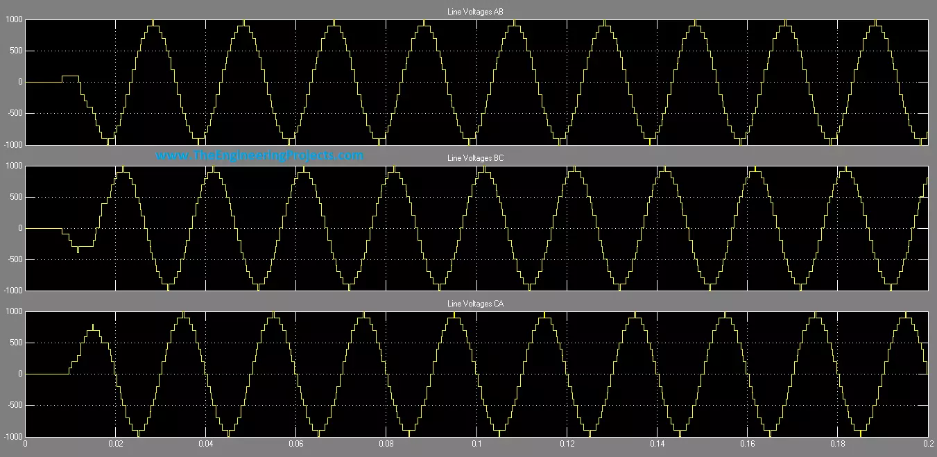
Hello friends! Today, we will study an 11-level, three-phase cascaded H-bridge inverter in MATLAB and Simulink. We will begin with one H-bridge cell, connect five cells in series to form a phase, and then combine three phase assemblies. This approach makes the voltage levels easier to understand than starting with a large diagram full of switching signals. The original project illustrates the overall arrangement and retains useful phase and line-voltage plots. We will keep those images while correcting the distinction between gate signals and power sources, the switching requirements for eleven levels, and the meaning of the older switch-model parameters. These details determine whether a simulation represents the intended converter. Our emphasis is a transparent simulation model. We will ...
Hello friends! Today, we will discuss fault detection of a gas turbine in MATLAB and Simulink. The aim is to understand how measurements, a reference model and decision logic can work together to identify abnormal behavior. We will move from the physical system to residual calculations, then examine how to test a detector without confusing a simulated alarm with a validated machine-protection system. The original project contains a useful collection of scopes, delays, summing blocks and alarm indicators. However, some block names and explanations need correction. In particular, a mu-law signal compressor is not an air compressor, and a piston-engine power-stroke model does not become a gas-turbine model merely by changing its displayed name. We will retain the original screenshots as a his ...
Hello friends! Today we will study multilevel inverters, starting with the switching waveform and then looking at the circuits that produce it. An inverter converts electrical power from a DC source into an AC output. Its switches determine the instantaneous voltage, while the modulation, load and filter determine how closely the useful output follows the required sine wave. In our earlier tutorials on pure sine wave inverter design and modified sine wave inverters , the main question was how to generate the alternating waveform. Here we will introduce intermediate voltage steps and examine what they change. More steps can improve waveform quality, but they also introduce more devices, measurements and control decisions. We will compare cascaded H-bridge, diode-clamped and flying-capacitor ...
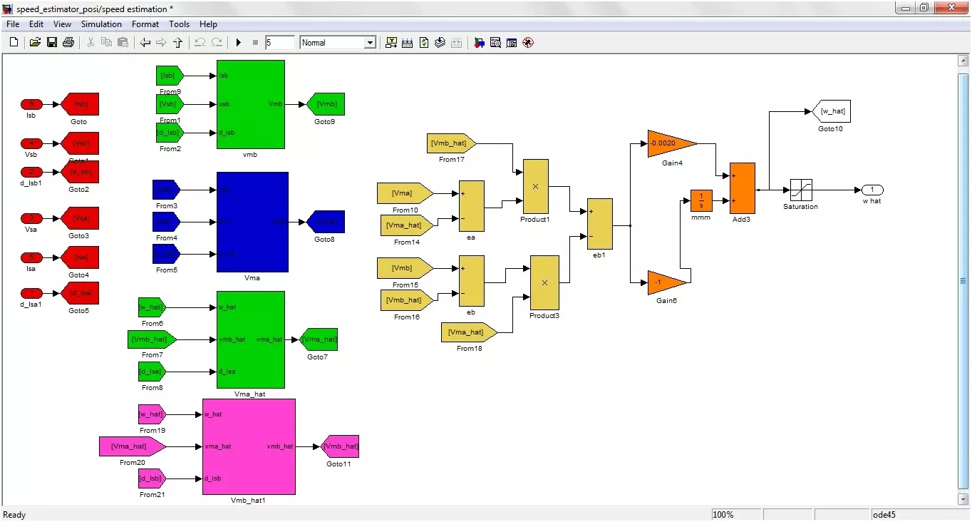
Hello friends! Today we will study sensorless speed estimation of an induction motor in MATLAB and Simulink. We will follow the original project's adaptive-estimation approach, beginning with the motor equations and then connecting those equations to the illustrated simulation blocks. The aim is to estimate rotor speed from electrical quantities rather than feed a measured shaft-speed signal into the estimator. In simulation, the motor model still provides a true speed for comparison. Keeping that reference separate from the estimator inputs is essential: otherwise, a model can appear sensorless while quietly using the answer it is supposed to estimate. The original project was developed in the MATLAB 2010 era and described as used with later 2012 and 2013 releases. The diagrams below docu ...
Hello friends! In this tutorial, we will learn how to share a Simulink design without distributing its editable implementation. You may have developed a controller, a signal-processing algorithm or a plant model that another person needs to simulate. The challenge is to give that person a usable component while keeping your original design private. The original version of this tutorial used a generated S-function. We will keep that method, explain what it actually protects and then look at the protected-model workflow available in current Simulink releases. These approaches produce different deliverables, so the right choice depends on what the recipient needs to do. If you are distributing MATLAB functions rather than Simulink models, see our tutorial on converting MATLAB M-files to P-fil ...