Hello everyone, I hope you all are doing great. In today's tutorial, I am going to share the detailed fIn the previous post, we have seen Introduction to PLC, which was quite simple and has the basic introduction to PLC. To day we are gonna have a look at Getting Started With Ladder Logic For PLC. Ladder Logic, also named as Ladder Logic Programming, is the programming language for PLCs. Its normally considered as the most difficult language among the engineers because of its complex structure, but if you ask me then I will say its the most interesting programming language.
Ladder Logic is different from the usual programming language of Microcontrollers like Arduino, PIC Microcontroller etc. Microcontrollers programming usually compiled from top ...
Hi friends, today we are going to learn one of the most important instructions in the PLC ladder which is MOVE instruction by which we can move data between different memory storage including input, output, marker, and variables. Also, data of different data types and sizes can be transferred from source to destination and source memory locations. For example data types including char, string, integer, floating, time and date can be transferred between source and destination. Memory location like input, output, and marker memory area can be acting as source or destination. Furthermore, a mask can be utilized to customize and control the part of data to be transferred between source and destination. In that move with a mask, the instruction uses a source address, a destination address, and ...
Hi friends and hope you are doing very well. Today we would like to take one tutorial which is very essential in the industry which is analog input processing for handling analog measurements of physical signals like temperature, humidity, pressure, distance, flow and level of liquids, etc. Typically, sensors produce two types of analog signals to represent the equivalent measured signal which is current and voltage signals. The currently produced signals would be within the range of 4-20 mAwhile voltage signals are in the range of 0-10 v. because, that output signals represent physical signals, the limits of output signals are 0 to 10 v for voltage based sensors and 4 to 20 mA for current-based sensors, these values should be scaled to represent ...
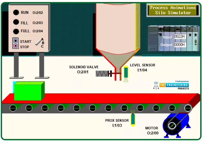
Hey guys! hope you are all very well. Today I come to you with a new process to learn, program, and simulate for practicing ladder logic more and more. The process we are going to implement today is a very common process that could be there in many many industries which is a silo process that aims to automate the process of filling containers or bottles with a liquid. Figure 1 shows the complete scene of the process including the system components, switches, indicators, sensors, and actuators that are integrated to make the system operate. Briefly and before going into deep details, let’s state what the system does and how it operates. Well! The system automatically fills the boxes that are traveling on the conveyor which is driven by a motor. They are filled with a liquid stored in the si ...
Hello friends, I hope you all are fine and enjoying good health. Today's tutorial, as the name shows, is on Introduction to PLC. PLC is an abbreviation of Programmable Logic Controller. Recently I worked on a project in which I have to design a Automated coffee Mixing Machine Using PLC. It worked quite good and I had a great time while working on it. After completing that project, it occurred to me that I haven't posted any tutorial on PLC. So I thought of starting this tutorial. This tutorial is not gonna cover in single post so my plan is to divide it in parts.
Today. I am gonna give an overview about PLC. We will have a look on basics i.e. what is PLC? Why we use PLC instead of microcontroller like Arduino or PIC Microcontroller? What's its adv ...
Hello friends, How are you doing? Today, we have a very interesting topic of PLC ladder programming which is how to detect the transition between true and false and from low to high?. I know you are asking why do we need that? Well! Imagine my friends, we want to start a motor when the input signal state changes from high to low or from false to true. Let us give two examples to highlight the edge detection techniques. Good examples of using edge detection-based logic are timers and counters. In counters, they are energized to count up or down when a signal appears and the same for timers. Figure 1 shows the difference between using the edge to control a motor. In the top part, the motor is controlled by an input switch. the output is ON and OFF b ...
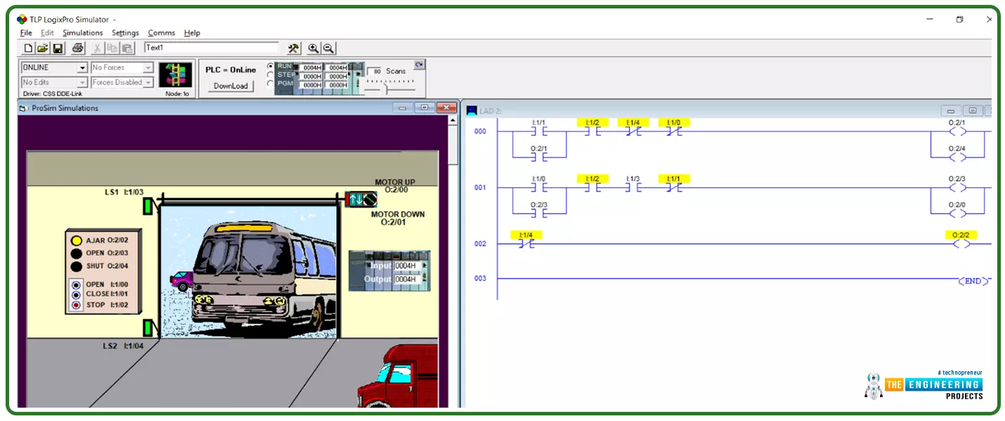
Hi Guys! hope you are doing great today! We come this time with a complete project to work out together starting from the point at which we sit with the client and receive the logical narratives that represent what they want to implement. We are going to start with a simple project this time and continue increasing the scale and complexity of the requirements through the incoming tutorials. The project we are going to implement today is one of the most common tasks that we can find in every place in our real life which is the control of the garage door. That could be found in private property or commercial buildings or public garages. Too many things need to be controlled in garage doors and several scenarios could come to your mind. However, take it as a rule of thumb that we design our p ...
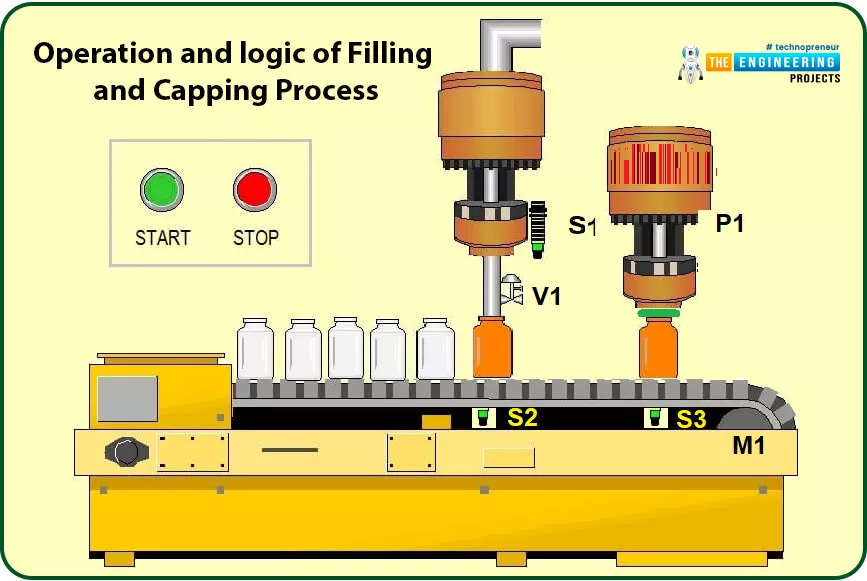
Hi friends, how are you doing? Today will integrate all of what we have learned so far in this series to build the first project based on ladder logic programming. Because we all are interested in industry, we pick one industrial project, Bottle Filling and Capping Projects, which is very common today. The problem we are going to solve today is bottle filling and capping. We have learned all basics of ladder logic including contacts and coils operation, logic gates, rising and falling edges, timers, and counters. So, today we will utilize all of these components to implement a complete ladder program of filling and capping problems.
Operation and Logic of Bottle Filling and Capping Process
For simplifying the operation of the process of filling and capping, fig. 1 shows the process flow ...
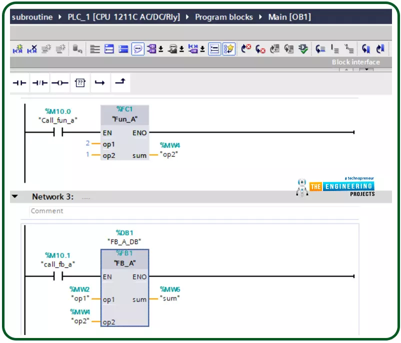
Hello friends, after completing that basic part of ladder logic programming, let us today go through one topic which is not essential to know to complete a PLC ladder program but it is important t have our code readable program and reusable pieces of code. That could happen by using what so-called a subroutine. So what is a subroutine? Well, it is a piece of code that includes a few rungs to perform specific tasks. that piece of code can be reused numerous times through the program when we need to call it for performing that task. That subroutine enables us to structure our code like building blocks so that the program will be readable very easy and also reusable later in other projects. The idea of dividing the program into routines to apply the divide and conquer technique is very crucia ...
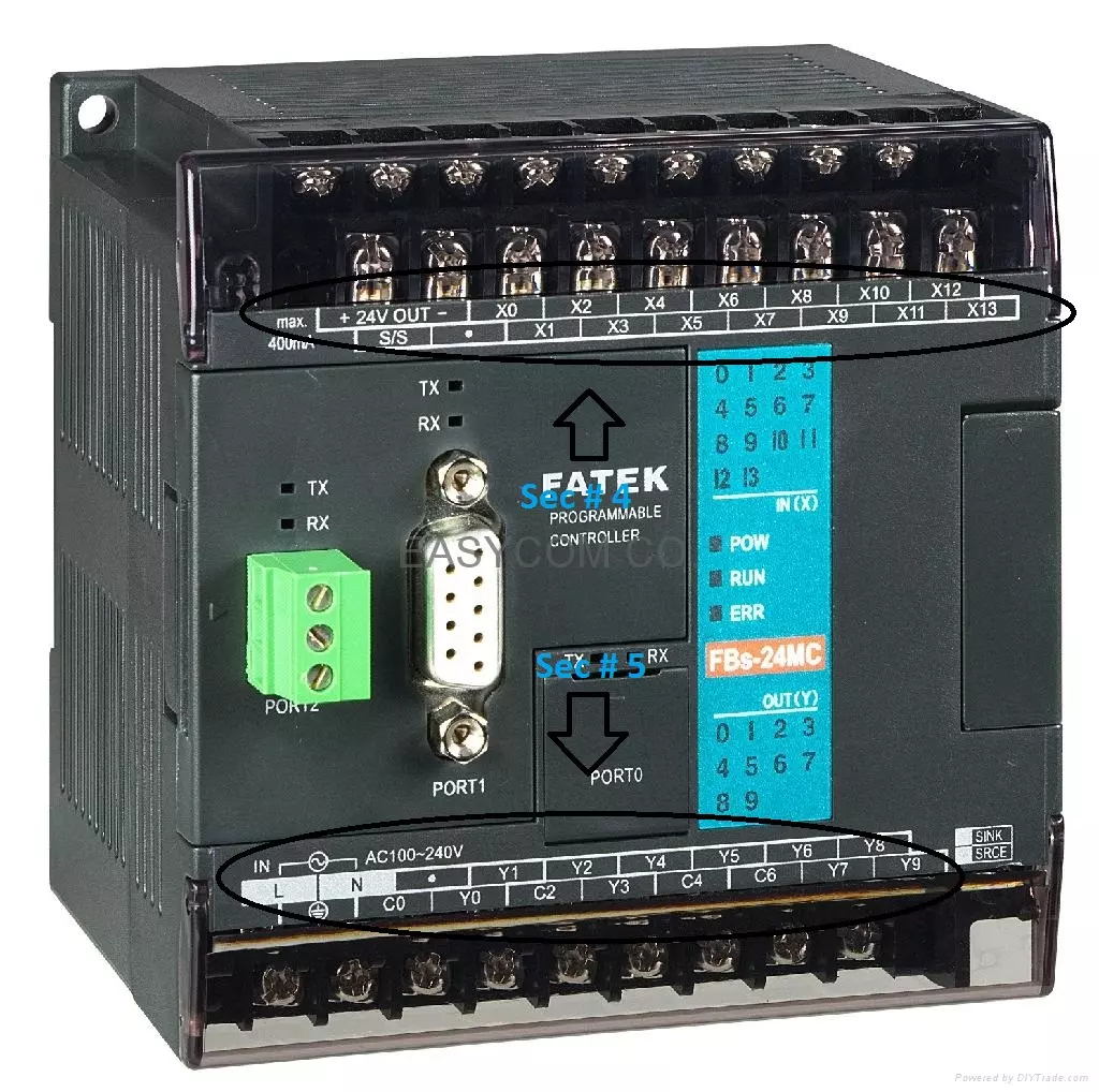
Hello friends, I hope you are doing very well! In today's tutorial, we will set up a simulation environment for Ladder Logic Programming. It's our second tutorial in Ladder Logic Programming Series. In our previous tutorial, we have seen a detailed Introduction to Ladder Logic Programming and we have seen that this programming language is used for PLC controllers.
As PLC is an Industrial Controller, it comes with built-in relays/transistors(with protection circuitry) and thus is quite expensive as compared to microcontrollers/microprocessors i.e. Arduino, Raspberry Pi etc. Moreover, if you are working on a real PLC, you need to do some wiring in order to operate it. So, in order to avoid these PLC issues at the beginning, instead of buying a PLC o ...