Hey buddies, hope you all are fine. In our previous tutorial, we studied Half Wave Rectification and have seen that it rectifies the half wave of the AC signal. Today, we are going to study Full Wave Rectification to rectify the complete AC source. We will design the simulation of the Full Wave Rectifier in Proteus software. So, let's get started:
What is Full Wave Rectification?
A comprehensive definition of full-wave rectification is:
- Full-wave rectification is a process to convert both cycles(positive & negative) of input(sinusoidal) wave to pulsating DC (Direct current).
We have studied in the previous lecture that Half Wave Rectifiers are used to convert only one cycle(either positive or negative) of an AC signal into a DC signal, thus dissipating the 50% energy of the overall signal. But in Full Wave Rectifiers, both cycles of the AC signal are converted into a single pulsating DC signal.
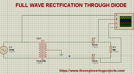
We used a single diode in our circuit to achieve half-wave rectification but for full-wave rectification, we need to create a bridge using 4 diodes. Here's the circuit diagram of Full Wave Rectification, designed in Proteus:

Why Full Wave Rectification?
Full Wave Rectification is always preferred over half wave rectification because of following factors:
- In half-wave rectification, half of the wave gets wasted as the diode suppresses the second half cycle. But if we add the diode bridge, we can easily get the complete signal i.e. both of its cycles.
- Full Wave Rectification gives higher output values with a low ripple factor.
Full Wave Rectifier Simulation in Proteus ISIS:
You can download the complete Proteus Simulation of Full Wave Rectifier, by clicking the below button:
Full Wave Rectification in Proteus
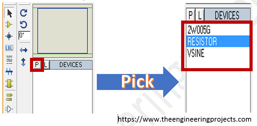
First of all, we have to pick the components from the Proteus Components Library. We are going to need these three basic components:
- Full Wave rectification bridge
- Resistor
- Alternating voltage source
- Go to the pick library button and select these components, as shown in the below figure:
- So, design the circuit for full-wave rectification in Proteus, as shown in the below figure:
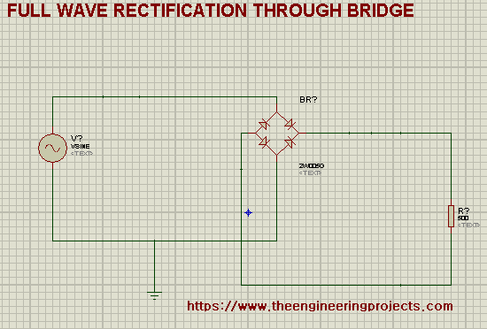
- Change the value of load resistance to 500 ohms.
- Set the Vsine Frequency to 1000Hz & amplitude to 120V.
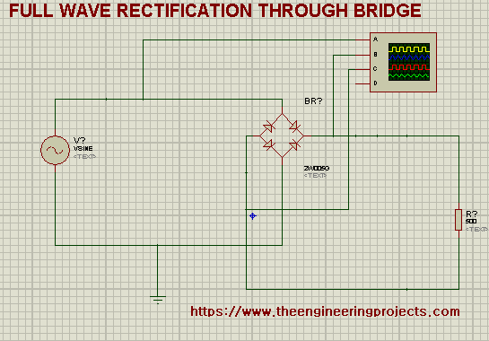
Now we are going to place an oscilloscope to monitor the input & output signals. You will find the oscilloscope in the "Virtual Instruments" section on the left bar. So, our final circuit with an oscilloscope is shown in the below figure:
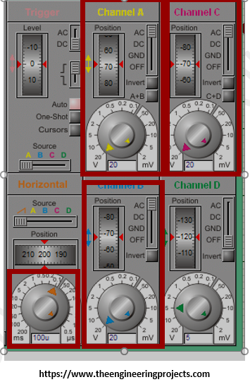
- The oscilloscope settings are shown in the below figure:
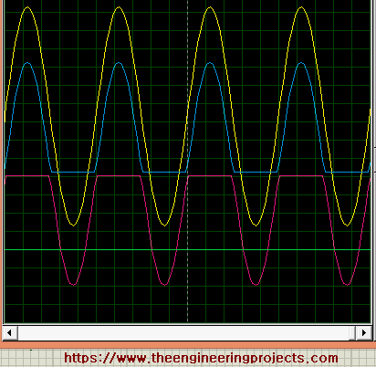
As you can see in the above figure:
- The Yellow(A Terminal) wave shows the sinusoidal wave. Whereas, the blue wave (B terminal) shows a positive half-cycle and the magenta one (C terminal) shows a negative half-cycle. And the magic is, both the outputs are direct currents and are combined in a single direction at the load resistance.
Thus, today we studied another simple Proteus experiment that shows what is full wave rectification, how to make the simplest circuit that shows the best output of full wave rectification and why we need the full wave rectification circuit. Till the next tutorial, take care!!!


