Hello friends, I hope you all are doing great. Today, I am going to share the new Magnetic Levitation Control Lab Library for Proteus, the fourth of our University Lab series. A steel ball floating in mid-air under an electromagnet, held there by nothing but a controller, is one of the most striking experiments in a control course, and one of the most demanding. The magnet pulls harder the closer the ball comes, so the ball sits on a knife edge: a little too close and it snaps to the magnet, a little too far and it falls. The controller has to correct it hundreds of times a second. The same idea floats maglev trains and holds the shafts of magnetic bearings.
Magnetic Levitation Control Lab Library for Proteus
Latest version: V1.0 (November 2026, this tutorial)
Other component libraries: C945 Transistor · PC817 Optocoupler · Relay Module · Resistor · 5 mm LED · Designer Colour LED · Push Button · Active Buzzer · Electrolytic Capacitor · Ceramic Capacitor · Tantalum Capacitor · Film Capacitor · 1N4007 Diode · Zener Diode · Schottky Diode · Supercapacitor · Photodiode · RGB LED · Bridge Rectifier · Flashing LED · Bi-Colour LED · SMD LED · Slide Switch · Toggle Switch · Rocker Switch · Micro Limit Switch · Emergency Stop Switch · SMD Resistor · Power Resistor · Resistor Network · Potentiometer · Trimmer Potentiometer · Slide Potentiometer · NTC Thermistor · DIP Switch · Fuse · Passive Buzzer · Mini Speaker · 7-Segment Display · LED Bar Graph · IR / UV LED · Small Transistors · TIP122 Darlington · N-MOSFET · P-MOSFET · PC817 Optocoupler · Filament Bulb · Power LED · Voltage Regulator · SCR and TRIAC · Inductor · Toroid Inductor · Crystal · Temperature Control Lab · DC Servo Lab · Ball and Beam · Rotary Pendulum · Coupled Tanks · AD8232 ECG · MyoWare EMG · GSR Sensor · MAX30205 · MCP4725 · MCP3008 · LM358 · NE555 Timer · INA128 · 74HC595
Helping Tools
- Serial Monitor Advance: a serial terminal window for the UART of your board
- Serial Monitor Expert: the serial monitor with extra debugging tools
- LCD Library for Proteus V3.0: 16x2, 20x4 and I2C LCDs to show your readings
Our library brings that lab into Proteus at true scale. It is our own maglev: an aluminium frame, a 12 V electromagnet with a steel core, a 19 mm steel ball resting on a stand under it, an infrared gap sensor across the gap, and the coil's MOSFET driver on the base. The physics covers the coil's current and its lag, the magnetic force and how fast it grows as the gap shrinks, and the ball falling and lifting between the magnet's face and the stand. The pop-up works out the linear model at the ball's gap, its unstable pole, the PD gains for the speed you ask for, and the overshoot and settling time of every move. The demo lifts the ball, moves it, adds an integral, and then takes the derivative away, from an Arduino UNO.
NOTICE: Our team has put a lot of effort into these small parts: the bodies, the animation and the pop-ups are all our own design, and you get them free. Your feedback is the fuel that keeps us going, so please tell us what you think in the comments below or in the Magnetic Levitation board of our forum. And if our free libraries help you, you can buy us a coffee. So, let's get started with the Magnetic Levitation Control Lab Library for Proteus:
What is Magnetic Levitation?
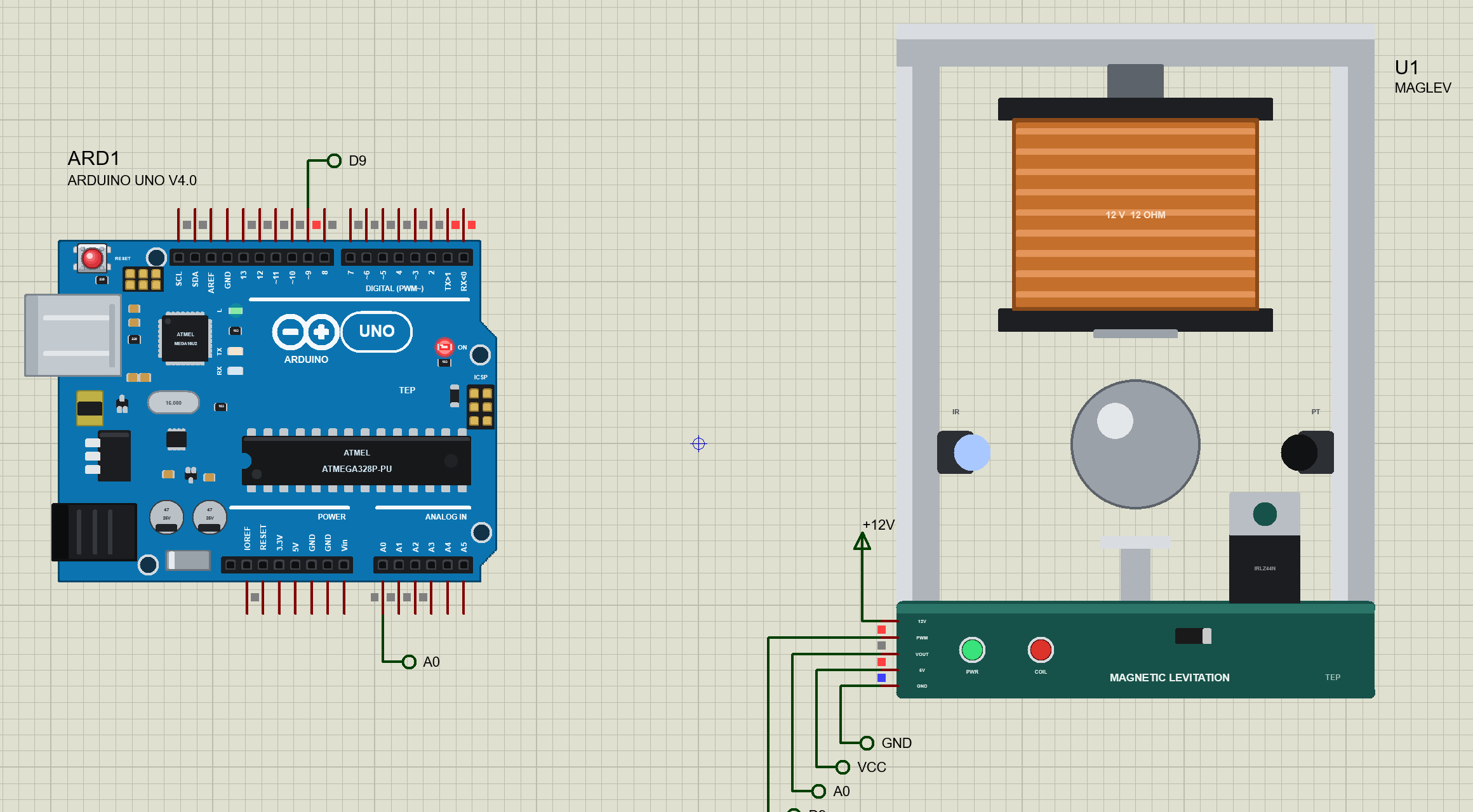
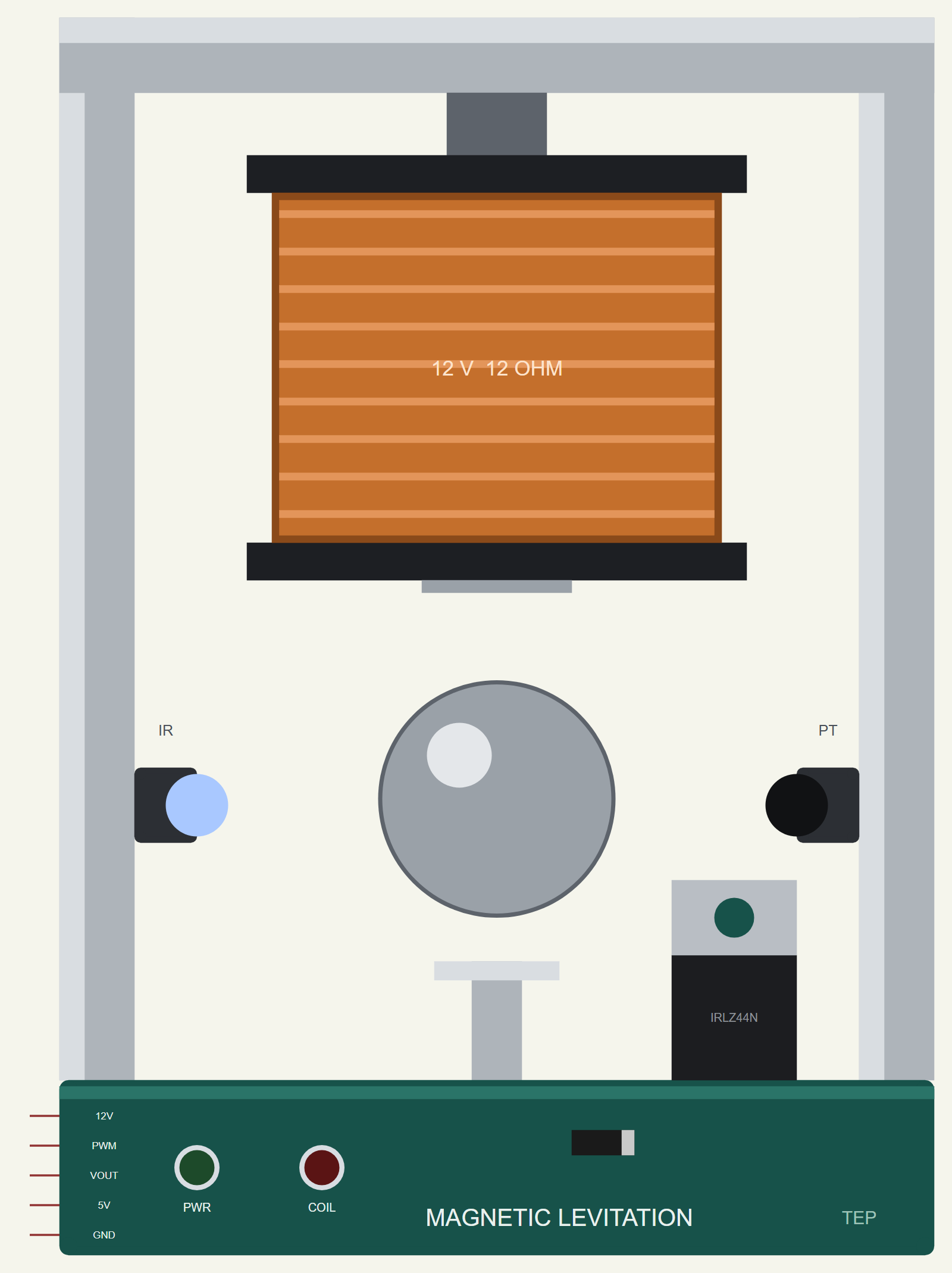
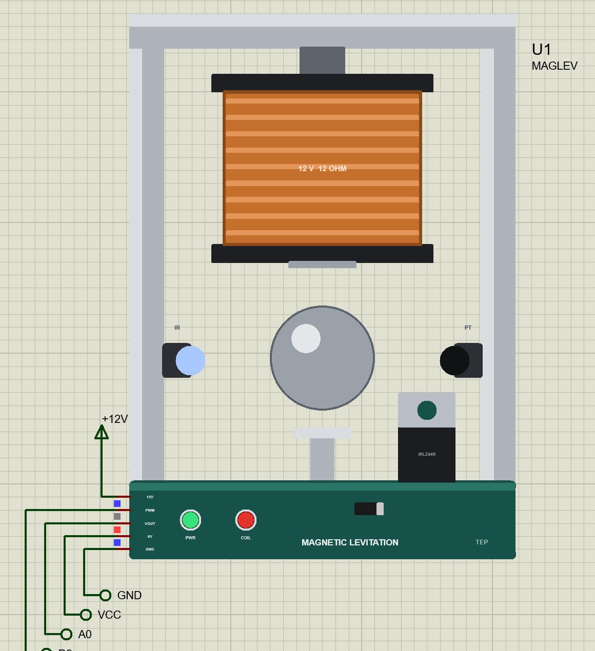
Magnetic levitation holds an object up with a magnetic field instead of a support. With a permanent magnet alone it cannot be done in a stable way: there is no point where the pull is right and stays right as the object moves. An electromagnet changes that. Its pull follows its current, so a controller that watches the gap and adjusts the current can hold a steel ball at any chosen distance. Our lab is 70 by 99 mm, drawn at its true size: an aluminium frame, the coil hanging from its top beam, the ball on a small stand 12 mm below the magnet's face, an infrared LED and a phototransistor facing each other across the gap, and a green base board with the coil's driver and two LEDs, PWR and COIL.
| The maglev lab | |
|---|---|
| Size | 70 x 99 mm |
| Electromagnet | 12 V, 40 mm coil, 12 Ω, 60 mH, steel core |
| Ball | steel, 19 mm, 28.2 g; resting on a stand 12 mm below the magnet |
| Gap sensor | IR LED and phototransistor across the gap: 0.4 V per mm at 9 mm |
| Driver | IRLZ44N logic-level MOSFET with a flyback diode, on the base |
| Pins | 12V, PWM (the gate), VOUT (the sensor), 5V, GND |
The Coil and Its Current
The Arduino does not set the coil's current directly. It switches the MOSFET on and off thousands of times a second, and the coil sees 12 V for part of each cycle. A coil's current cannot jump: it rises and falls with the time constant of its inductance over its resistance, 60 mH over 12 Ω, 5 ms. Between pulses the flyback diode keeps the current flowing and protects the MOSFET from the coil's spike. Full on, the coil draws 1 A. The lab measures the gate's pulses edge by edge, so the duty and the frequency are exact, and works out the current from them.
The Magnetic Force
The pull of an electromagnet on a steel ball grows with the square of its current and falls quickly as the gap opens. The lab uses the classic form, F = C i² / (gap + 5 mm)², where the 5 mm accounts for the core's face and the ball's shape and C = 1.87 x 10⁻⁴ N m²/A². With these numbers 0.5 A holds the 28.2 g ball, whose weight is 0.277 N, at 8 mm. From the stand, 12 mm away, it takes about 0.65 A to lift it. The ball itself simply falls under gravity against the pull, stopped by the stand below or the magnet's face above.
The Unstable Pole
Hold the ball at 8 mm with exactly 0.5 A and nudge it up: the gap shrinks, the pull grows, and the ball accelerates further up. Nudge it down and the pull weakens and it falls. Linearized about the hold point, the gap obeys x'' = p² x, with p = √(2g / (gap + 5 mm)): the unstable pole, 38.9 rad/s at 8 mm. A small error doubles every 18 ms. That is the knife edge the controller balances on, and it is far quicker than the ball and beam's: a maglev loop has to run at hundreds of times a second.
PD Control for an Unstable Plant
The controller sets the current around the holding current, i = i0 + Kp x error + Kd x speed. The proportional part makes a spring: more current when the ball sags, less when it rises, and it has to be strong enough to beat the unstable pole before it does any good. The derivative part is the damper; without it the ball swings around the target, and with the coil's lag the swings grow. With the force per amp, 39.2 m/s² per A at 8 mm, the closed loop has ωn² = Ki Kp - p² and 2ζωn = Ki Kd. The pop-up designs for ωn = 60 rad/s (the property WN) and ζ = 0.7: 0.13 A per mm and 2.14 mA per mm/s, or through the coil's 12 Ω, 1.56 V per mm and 0.0257 V per mm/s. On a 12 V supply that is 13.0 % of duty per mm. A PD loop leaves a small offset; an integral term removes it.
The Gap Sensor
The infrared LED shines across the gap at the phototransistor, and the ball shades part of the beam: the further down the ball hangs, the more light gets through. The lab's output is 2.5 V + 2.0 V x tanh((gap - 9 mm) / 5 mm), 0.4 V per mm in the middle of its range, with a couple of millivolts of noise. The sketch turns the curve around to get the gap in millimetres.
Features of the Magnetic Levitation Control Lab Library for Proteus
- The real look, at true scale: a 70 x 99 mm lab with the coil, the ball, the stand, the IR sensor pair, the IRLZ44N and its diode; at Run the ball floats on the sheet and the COIL LED glows with the current.
- Real physics: the coil's current with its 5 ms lag and its flyback diode, the force law, the ball between the magnet and the stand.
- Exact gate timing: every edge of the PWM is timed, at any frequency.
- The model at the gap: the holding current, the unstable pole and the force per amp, worked out where the ball is held.
- PD gains from the model: for the closed-loop speed you choose (WN) and ζ = 0.7, in volts and in percent of duty.
- Every move measured: rise time, overshoot, peak time and settling time; lift-offs, drops and hits on the magnet logged.
- A pop-up: the ball under the magnet with its pull against its weight, the gap, coil and duty since the start, eight live values, graphs, an event log and a check page.
- A complete package: about 1.2 MB with the library, our Arduino UNO V4.0 and the demo, without the source code of the model.
The Maglev Lab in Proteus
The device is MAGLEVTEP in TEPMAGLEV.LIB, under Control Labs, with the prefix U and the model TEPMAGLEV.DLL, a mixed model: the gate is digital and timed edge by edge, the sensor and the supplies are analog. Search MAGLEV in Pick Devices. Its five pins are on the left edge of the base: 12V for the coil, PWM for the MOSFET's gate, VOUT for the gap sensor, 5V for the sensor and GND.
The Properties
| Property | What it does |
|---|---|
| The ball at the start (GAP) | mm below the magnet; 12 is on the stand |
| Sensor noise (NOISE) | mV RMS on VOUT, 2 by default |
| Closed-loop speed (WN) | rad/s: the pop-up's PD gains are for this speed and ζ = 0.7, 60 by default |
Download Magnetic Levitation Control Lab Library for Proteus
Click the button below to download Magnetic-Levitation-Control-Lab-Library-for-Proteus-v1.0.zip (about 1.2 MB, without the source code of the models):
Magnetic Levitation Library for Proteus V1.0- README.txt: installation, the demo, the wiring, troubleshooting and the limits.
- Proteus Library Files:
TEPMAGLEV.LIBand ourArduinoV4TEP.LIB. - Proteus Model Files:
TEPMAGLEV.DLLandTEPARDUINO.DLL. - Arduino Code: the demo sketch.
- Proteus Simulation: the demo project, its HEX file and copies of the DLLs.
No Proteus yet? Read How to Download and Install Proteus 7 and 8. New to libraries? Follow How to Install a New Library in Proteus.
How to Install Magnetic Levitation Control Lab Library for Proteus
- Close Proteus and extract the whole zip file, for example to your Desktop.
- Copy the files from Proteus Library Files into the LIBRARY folder of Proteus.
- Copy the files from Proteus Model Files into the MODELS folder.
- Delete
TEPMAGLEV.IDXfrom the LIBRARY folder if it is there. - Start Proteus, press P and search for MAGLEV.
Demo: Lift-Off, PD Moves, an Integral and No Derivative
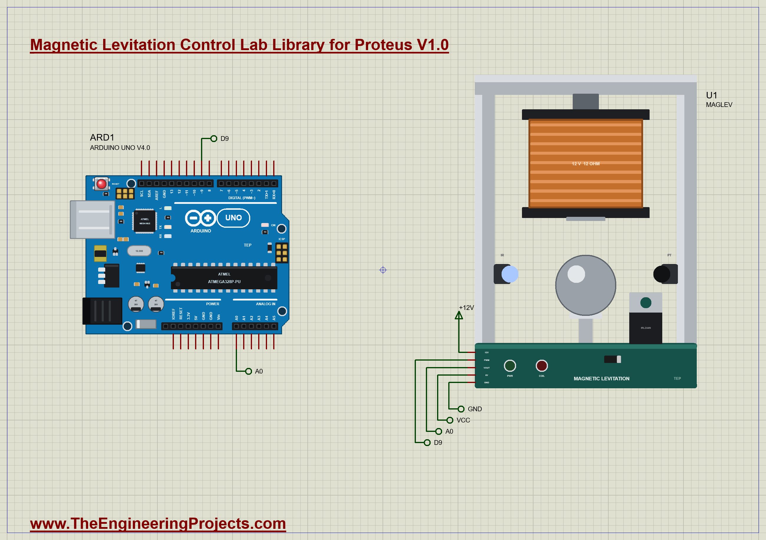
The demo is just the lab and our Arduino UNO Library for Proteus V4.0, with its built-in monitor, the same window as our TEP Serial Monitor Advance for Proteus. The lab's PWM goes to D9, VOUT to A0, 5V and GND to the rails, and 12V to a +12V terminal. Open Maglev-PID-ArduinoUnoV4.pdsprj.
The Sketch
The sketch sets Timer1 to run without a prescaler, so D9's PWM is 31.4 kHz, fast against the coil's 5 ms. It turns the sensor's curve around to read the gap in millimetres:
float gapMm(int a) {                              // the sensor's curve, turned round: gap = 9 + 5 x atanh((V - 2.5) / 2.0)
  float y = (constrain(a * 5.0 / 1023.0, 0.52, 4.48) - 2.5) / 2.0;
  return 9.0 + 2.5 * log((1 + y) / (1 - y));
}
Every millisecond the loop reads the gap, works out the ball's speed from the real time since the last pass, and sets the duty: the voltage that holds the ball at the target, (target + 5 mm) / 26 A through 12 Ω, plus the PD corrections, plus the integral once it is switched on:
  float e = gap - ref;                            // the ball too low (gap too big): more current
  if (useI) integ += e * dt;
  float u = R_COIL * (ref + 5.0) / 26.0 + KP * e + kd * speed + (useI ? KI * integ : 0);
  duty = on ? constrain(u / VS, 0, 1) : 0;
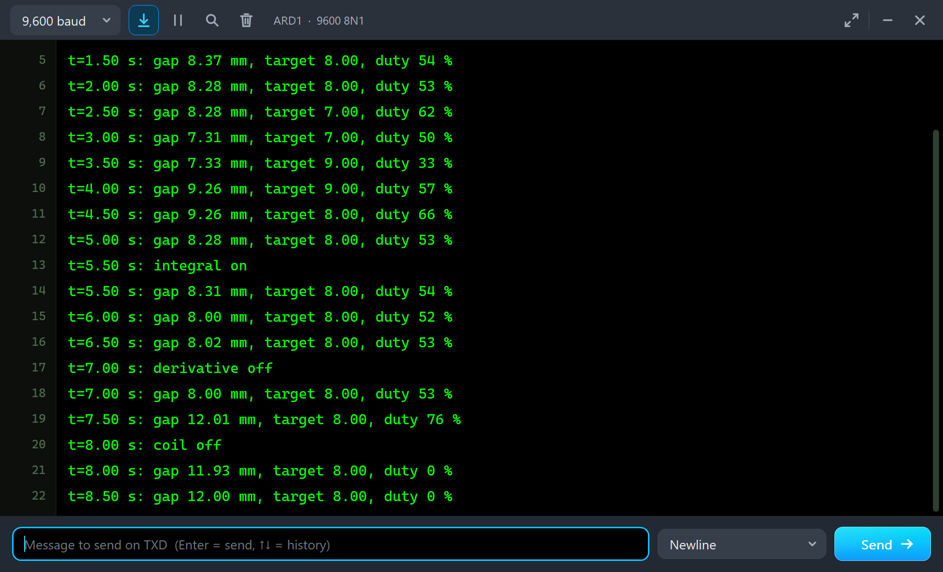
At 0.5 s the coil comes on and the target ramps from 12 mm, the stand, to 8 mm over a second. Then the target goes to 7 mm at 2.5 s, to 9 mm at 3.5 s and back to 8 mm at 4.5 s, with the pop-up's gains, 1.56 V per mm and 0.0257 V per mm/s. At 5.5 s the integral comes in. At 7 s the derivative goes off, and at 8 s the coil switches off. Every half second the sketch prints the gap, the target and the duty.
Run the Demo
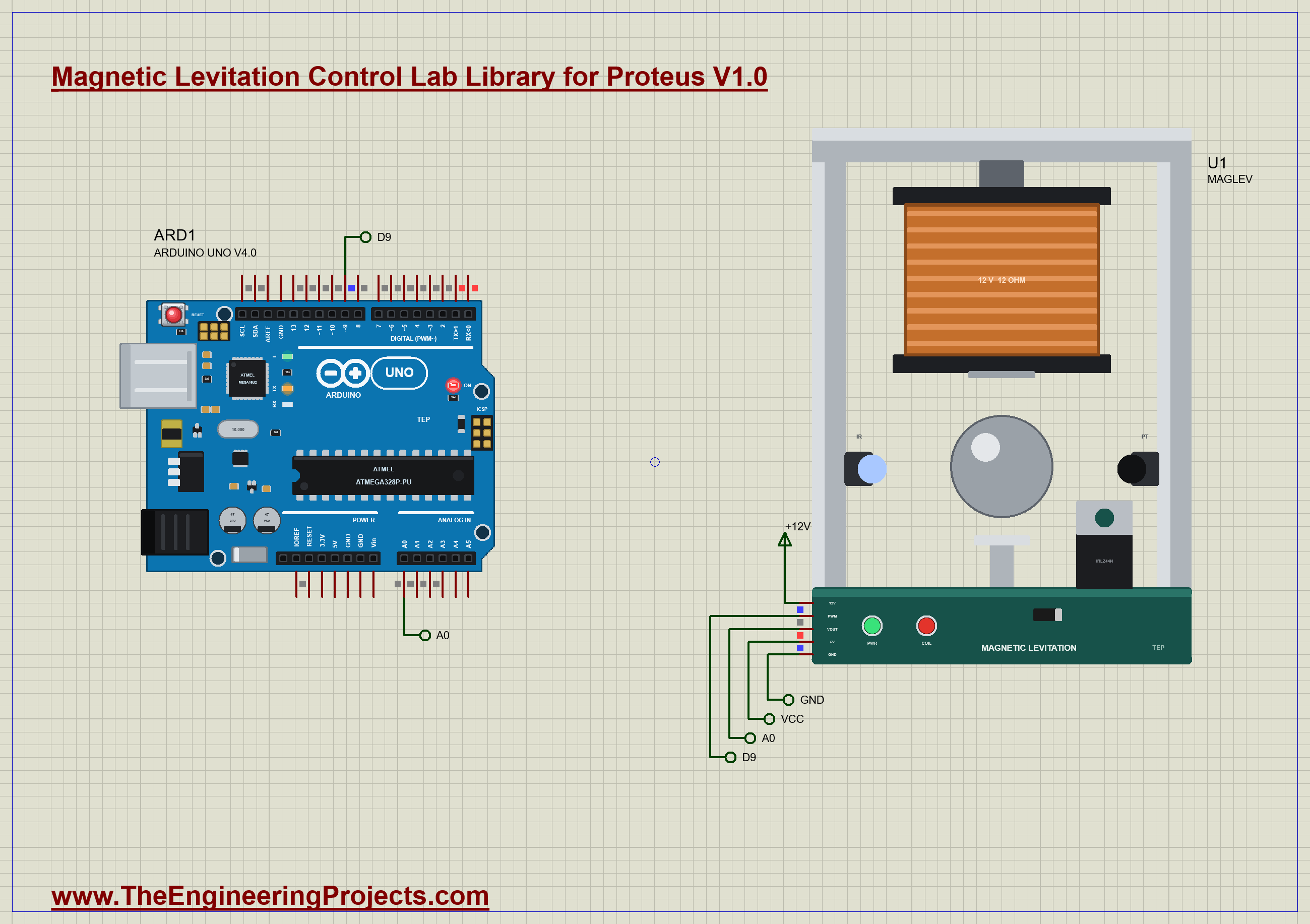
Open the project and press Run. The demo runs nearly 9 simulated seconds, which Proteus ran in under two minutes on our PC. On the sheet the ball leaves its stand and hangs under the magnet, and the COIL LED on the base glows with the current. Click the lab to open its pop-up; everything below is from that one run, the demo exactly as it ships.
Lift-Off and the PD Moves
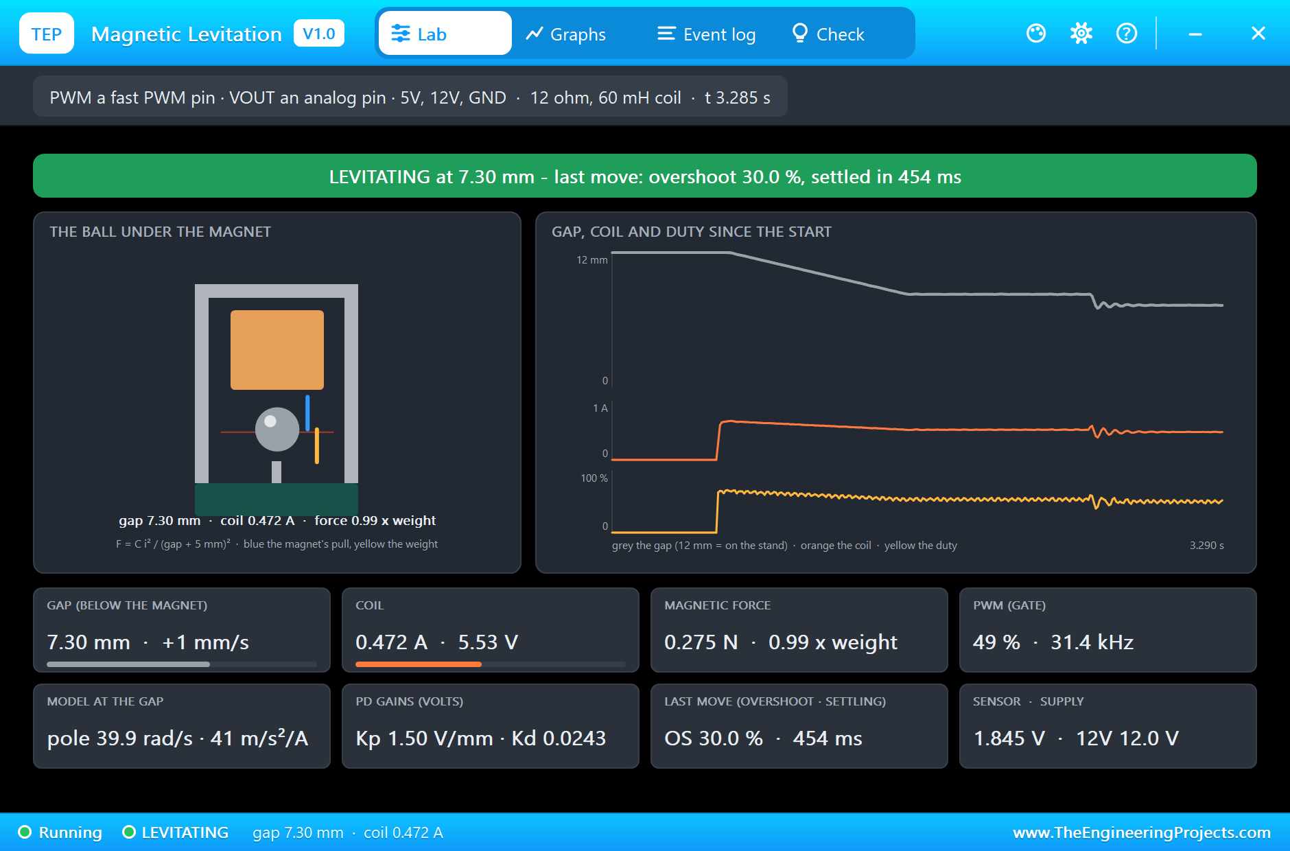
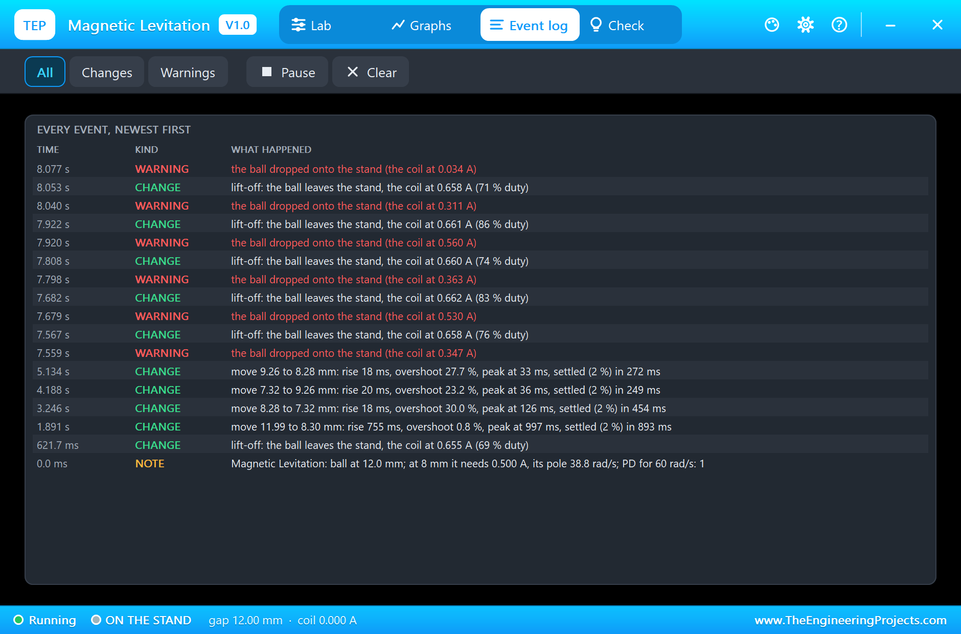
The ball leaves its stand at 0.62 s, with the coil at 0.655 A and 69 % duty, and follows the target up; it settles at 8.28 mm, 0.28 mm short of 8 mm with 53 % duty, the offset of a PD loop. The pop-up measured the lift as a move: 755 ms from 10 % to 90 %, 0.8 % overshoot, settled in 893 ms. The steps are much quicker. From 8.28 to 7.32 mm the ball rises in 18 ms, overshoots by 30.0 % and settles in 454 ms; from 7.32 to 9.26 mm, 20 ms, 23.2 % with the peak at 36 ms, and 249 ms; from 9.26 to 8.28 mm, 18 ms, 27.7 % with the peak at 33 ms, and 272 ms. The pop-up opened at 3.3 s shows the ball held at 7.30 mm with the coil at 0.472 A, 49 % duty, and the pull 0.99 times the ball's weight; its model at that gap gives an unstable pole of 39.9 rad/s.
Why the Overshoot Is Bigger Than the Design
The design asked for ζ = 0.7, about 5 % overshoot, and the moves overshoot by 23 to 30 %. The design assumes the current follows the controller at once and the speed is known exactly. Neither is true: the coil's current lags its voltage by 5 ms, and the speed comes from a filtered difference of the gap readings. At 60 rad/s those few milliseconds take a large part of the damping. This is the classic maglev lesson, and the pop-up's third tip says it: a faster loop needs a current amplifier or a lead compensator. Try a lower WN and see the overshoot shrink.
The Integral
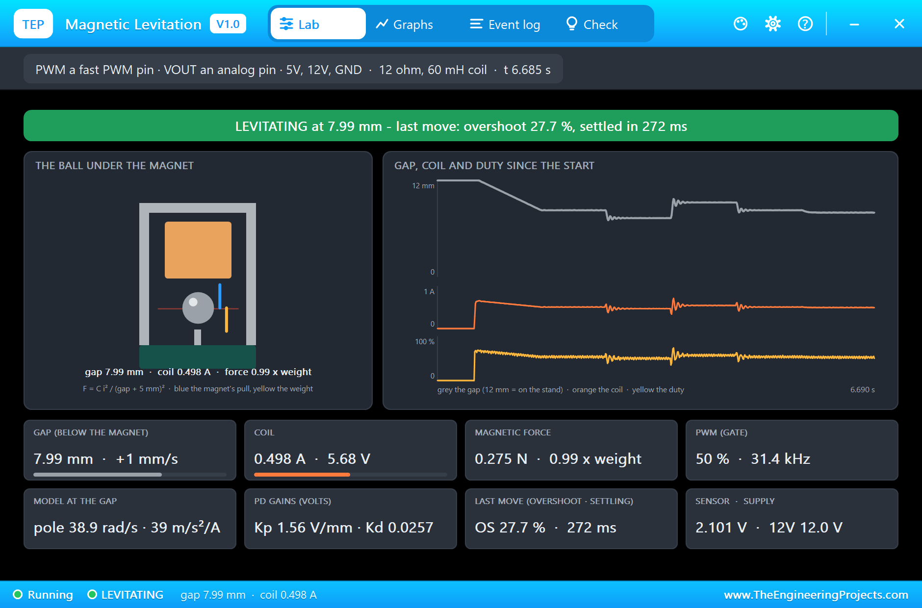
At 5.5 s the integral comes in. It adds up the remaining error and raises the duty a little until the error is gone: the gap goes from 8.31 mm to 8.00 mm within half a second, at 52 % duty. The pop-up opened at 6.6 s shows the ball held at 8.0 mm.
No Derivative
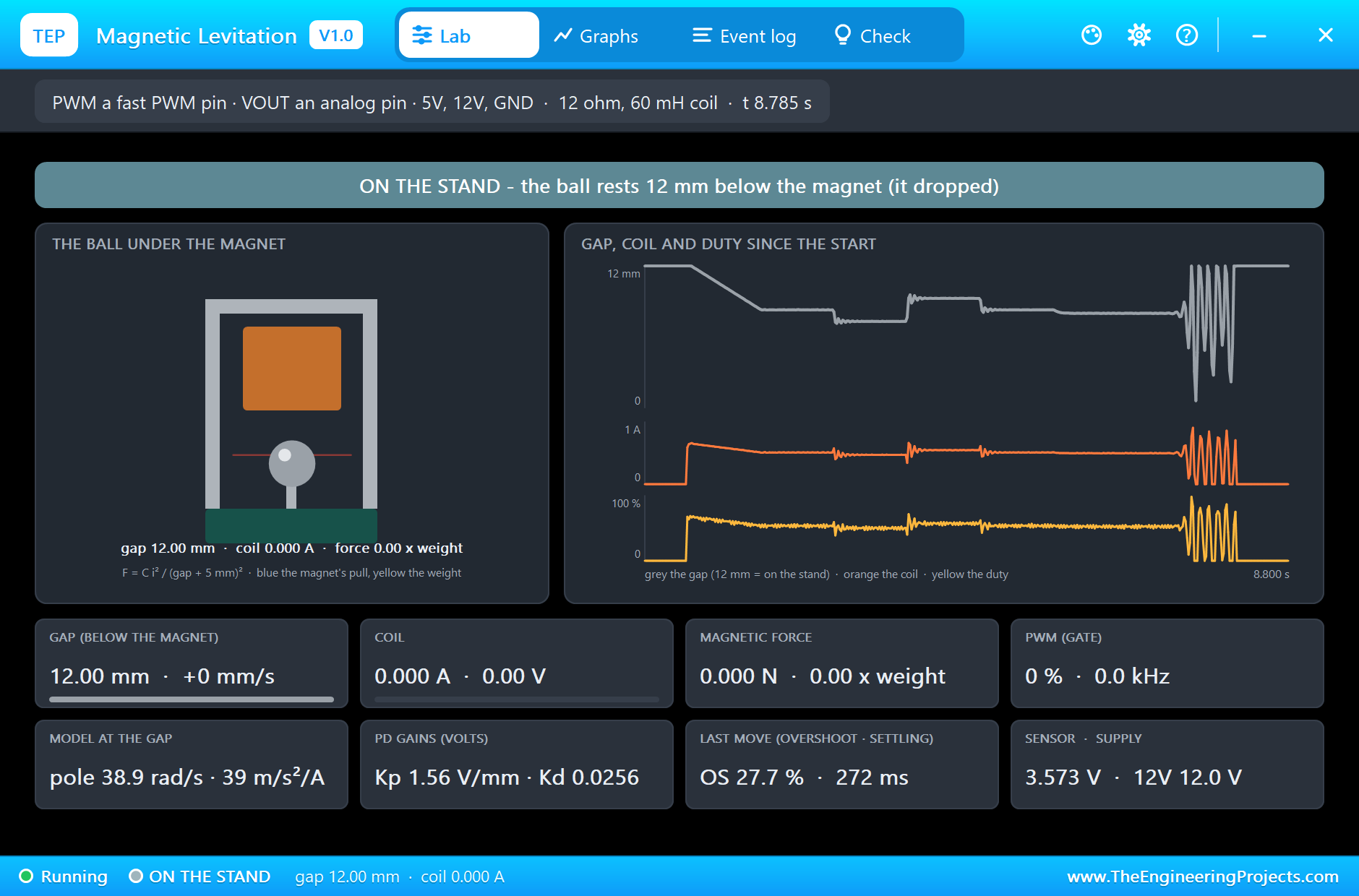
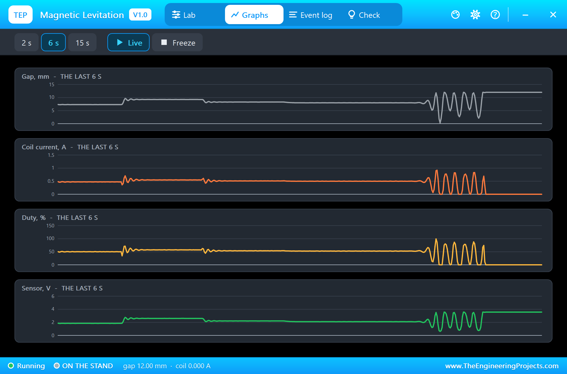
At 7 s the sketch switches the derivative off. With only the spring and the integral left, and the coil's lag in the way, the oscillation grows at once: the ball drops onto its stand at 7.56 s, the loop lifts it again, it drops again, and the Event log fills with lift-offs and drops until the coil switches off at 8 s. The trend on the main page shows the clean steps, then the ball hammering between the stand and the target.
The Monitor
The UNO's monitor prints the gap, the target and the duty every half second: 8.28 mm at 2.00 s with 53 % duty, 7.31 mm at 3.00 s after the step to 7 mm, 9.26 mm at 4.00 s, 8.00 mm at 6.00 s once the integral has done its work, then 12.01 mm at 7.50 s, the ball back on its stand with the duty at 76 % as the loop tries to lift it.
The Graphs, the Log and the Check Page
The Graphs page plots the gap, the coil current, the duty and the sensor voltage over the last 2, 6 or 15 simulated seconds. The Event log lists the lift-off, every move with its numbers, and every drop with the coil's current at that moment.
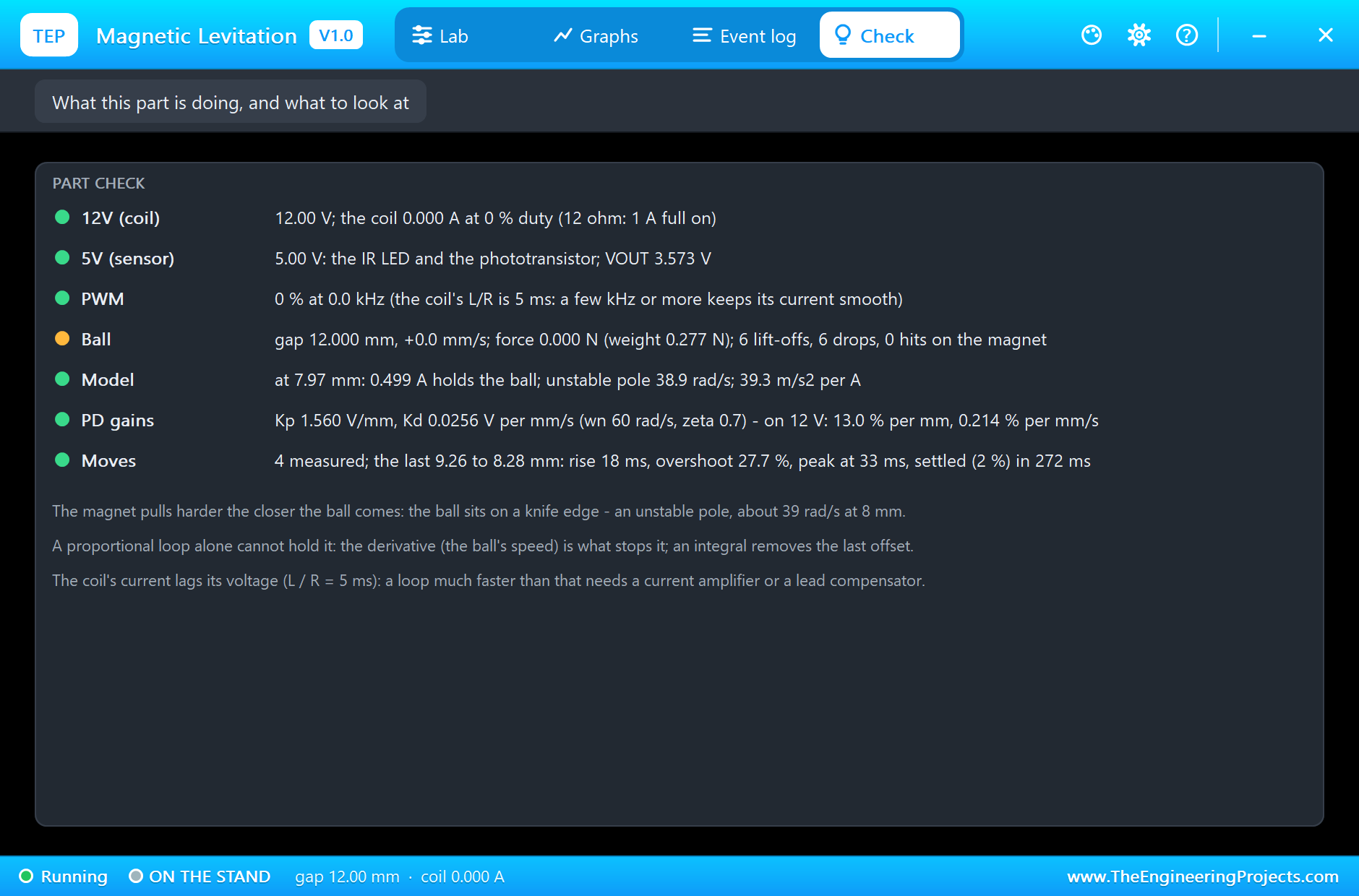
The Check page sums up the part: the 12 V and 5 V supplies, the PWM, the ball with its lift-offs, drops and hits on the magnet, 6 lift-offs and 6 drops by the end and none on the magnet, the model at 7.97 mm (0.499 A holds the ball, the unstable pole 38.9 rad/s, 39.3 m/s² per A), the PD gains (1.560 V per mm and 0.0256 V per mm/s, 13.0 % of duty per mm) and the last move.
Try It Yourself
- Set WN to 30, copy the pop-up's gains into the sketch, and see the overshoot shrink as the loop slows down.
- Halve the PWM frequency again and again until the coil's current ripples and the ball buzzes.
- Raise NOISE and watch the derivative turn it into duty jitter; then filter the speed more.
- Hold the ball at 10 mm and at 6 mm and compare the unstable pole and the gains the pop-up gives.
- Add a lead compensator in place of the plain derivative and see how much damping comes back.
Ideas to Extend the Demo
- Make the target follow a potentiometer and float the ball up and down by hand.
- Send the gap to a PC and identify the unstable pole from the data.
- Add a current sensor and an inner current loop, as real maglev amplifiers do.
- Try a state-feedback design with an observer for the ball's speed.
Your Own Sketches
The demo sketch is in the zip file, and you can change it in the Arduino IDE. New to Arduino? Start with our Arduino Tutorial for Beginners. Export the compiled binary, and set the UNO's PROGRAM property to the new file. Our guide on How to get the HEX file from Arduino shows you where the file ends up.
Things to Know Before Using a Real Lab
- The coil gets warm: 0.5 A in 12 Ω is 3 W in a small bobbin; give it air and the MOSFET a heat sink if it runs for long.
- Never leave out the flyback diode: without it the MOSFET sees the coil's spike at every switch-off.
- Keep the PWM fast: kHz or more, or the current ripples and the ball buzzes.
- Start from a stand: a steel ball near a magnet snaps to it; lift from a support and limit the current near the face.
- Mind the light: a real optical gap sensor sees room light too; shield it or modulate the LED.
Troubleshooting
- NO 12 V: the gate is driven but 12V is missing, so the coil cannot lift.
- The ball does not leave the stand: not enough current; check 12V and the duty; about 0.65 A lifts it from 12 mm.
- AT THE MAGNET: the ball snapped to the magnet's face; too much current near it, or the sign is wrong: a gap too big must raise the duty.
- The ball buzzes: the PWM is too slow for the coil.
- The part is not simulated:
TEPMAGLEV.DLLis missing from MODELS and from the project folder.
Limitations of the Simulation
- The coil's inductance is fixed; in a real maglev it changes with the gap.
- The core never saturates, and there are no eddy currents.
- The ball moves only up and down: no spin, no sideways swing.
- Arduino is a name of Arduino; this library is not made or endorsed by Arduino or Labcenter.
- Tested in Proteus 8.5 in November 2026 (the demo as shipped). Proteus 7 is not supported.
So, that was all about the Magnetic Levitation Control Lab Library for Proteus. I hope it helps you run the most dramatic lab of a control course on your own PC: a ball held on a knife edge by a loop a thousand times a second, the model behind it, and what the derivative and the integral each do. If you have any questions, ask in the comments and I will help you out. Till the next tutorial, take care and have fun!